
Dual-Arm Compliance Control with Robust Force Decomposition
William Freidank
1,2
, Konrad Ahlin
2
and Stephen Balakirsky
2
1
Department of Mechanical Engineering, Georgia Institute of Technology, 801 Ferst Dr, Atlanta, Georgia, U.S.A.
2
Georgia Tech Research Institute, 640 Strong Street, Atlanta, Georgia, U.S.A.
Keywords:
Dual-Arm Control, Compliance Control, Artificial Potential Field, Secant Method, Force Decomposition,
Beam Method, Robot, Robotic, Manipulator.
Abstract:
Realtime, compliant control of dual-arm robots has been an open area of investigation for versatile object
manipulation. Recent research has focused on leader-follower, hybrid, and impedance control techniques.
This paper proposes a guaranteed-convergence artificial potential field in order to leverage its advantages in
computational speed and functional quality. Additionally, compliance control is integrated using a novel force
decomposition method. Experiments are performed on a 14 Degree-of-Freedom (DoF) dual-carriage rail,
with two UR5e robots to validate the new method’s accuracy and demonstrate the feasibility of the unified
controller.
1 INTRODUCTION
Robotics have steadily gained greater responsibility
in industrial settings, especially in structured and pre-
dictable assembly operations. One major challenge
to broader implementation is the inability to adapt
highly task-specific solutions to new objects and situ-
ations (Kousi et al., 2018). Dual-arm, compliant ma-
nipulators promise greater versatility in the push for
reliably performing maintenance operations with un-
predictable disturbances and features.
There are two kinds of compliance: internal and
external. A human uses “external” compliance when
using their arms and hands to install an object guided
by a peg and socket. The force felt from the socket
correcting the orientation of the peg during insertion
allows the human to adjust the insertion to comply
with the actual geometry. A human uses “internal”
compliance when an object cannot be grabbed at an-
ticipated positions. For example, if the object is larger
due to a design change, the human will feel the ob-
ject’s larger size forcing the human to “comply” with
a greater spacing of their arms and hands. The prob-
lem of internal compliance is unique to systems with
more than one simultaneous grasp point.
In robotics, compliance control may be realized
passively through innovative mechanical designs such
as variable stiffness actuators (Wolf et al., 2016) or
actively through more classical methods such as par-
allel force/position, impedance, or admittance control
(Calanca et al., 2016)(Seraji, 1994). In the active
case, compliant control may be seen as a form of con-
tinuous feedback force control. Compliance can be
achieved at the level of the object, at the level of robot
joints, or both, as explored in (Ren et al., 2021).
(Hu et al., 2021) proposed two techniques of solv-
ing the internal and external compliant forces for
dual-arm compliant control: a master-slave force con-
trol and a shared force control. The master-slave tech-
nique assumes an expected force and torque at one
manipulator’s end-effector, reducing the number of
unknown variables to only those at the other manip-
ulator, and then solves the system uniquely. Vari-
ations of this approach have been used elsewhere
(Xian et al., 2017)(Gao et al., 2022). In the second
method, the shared force technique allows for object-
level force commands, but suffers from an undeter-
mined system of equations. (Song et al., 2021) ex-
plored the control of internal and external forces when
employing the shared force technique. The primary
challenge in question becomes properly decompos-
ing applied forces into internal and external contribu-
tions at the robot end-effectors. Pseudoinverse-based
methods have the advantage of being readily extended
to k number of manipulators, as leveraged in (Song
et al., 2022). (Walker et al., 1991) proposed a No-
Squeeze pseudoinverse designed to yield end-effector
wrenches that are free from internal effects on the ob-
ject. However, their method imposes the requirement
of equal load distribution, which may not correspond
to real operating conditions. A further exploration
was made in (Erhart and Hirche, 2015) of the prob-
lems arising frrom unintended internal wrenches pro-
duced by different pseudoinverses, presenting an an-
616
Freidank, W., Ahlin, K. and Balakirsky, S.
Dual-Arm Compliance Control with Robust Force Decomposition.
DOI: 10.5220/0012177300003543
In Proceedings of the 20th International Conference on Informatics in Control, Automation and Robotics (ICINCO 2023) - Volume 1, pages 616-623
ISBN: 978-989-758-670-5; ISSN: 2184-2809
Copyright © 2023 by SCITEPRESS – Science and Technology Publications, Lda. Under CC license (CC BY-NC-ND 4.0)
alytically inspired parameterized inverse. In this pa-
per, we propose a shared-force technique that avoids
mathematical optimizations in favor of a closed form
solution drawing upon a physically inspired analysis
incorporating established models in classical statics.
A robust control methodology may use simultane-
ous path planning and compliance control to achieve a
larger trajectory objective. However, compliant con-
trol for large or heavy objects may require the co-
ordinated control of multiple robotic manipulators.
In such high-dimensional problems, choice of a path
planning method comes down to computation time as
a function of algorithm complexity, which for search-
based methods, such as A* and Rapidly-exploring
Random Trees (RRT), increases exponentially with
the dimensions of space (LaValle, 2006). Neither can
reliably solve the path planning problem with real-
time capability in a fourteen-dimensional space, as
necessary for the robot cell used for our research.
Artificial Potential Fields (APF), which are
function-based approaches to path planning, offer
compelling advantages for path planning in high di-
mensional spaces. APF uses a goal location and
obstacles to calculate a simulated “potential” func-
tion, the gradient of which acts as a pseudo-force
that directs the manipulators toward the target. The
complexity of the APF algorithm scales linearly with
space dimensions rather than exponentially making
it ideal for high DoF path planning (Khatib, 1985)
(Khatib, 1986). APF has well-known disadvantages
for mobile robotics (Omar et al., 2016), but these
performance issues can be alleviated by adjusting
the potential function using an approach called the
“Secant Method” (Ahlin et al., 2018). Furthermore,
APF theory can be extended to manipulators. (Kim
et al., 2021) demonstrated that the Secant Method can
plan for two, six-DoF manipulators to have coordi-
nated motion. In their research, coordinated control
alongside a mechanical compliance device known as a
“wiffletree” allowed two manipulators to carry a pay-
load that was heavier than either could have carried
individually. In this work, we adopt insights from
(Kim et al., 2021). First, the path planning will be
solved in real-time at approximately 500 Hz to match
the controller. (Kim et al., 2021) used this frequency
to ensure that the two manipulators’ end-effectors
maintained the same relative position, despite varia-
tions and errors that manifested during path execu-
tion. Second, we compute the path plan in Cartesian
task space and translate the commanded pseudo-force
to joint space via a Jacobian transpose. Error values
can thus remain in the task space domain, which im-
proves the relevance of the error to real-world appli-
cations and eliminates the need to translate the target
location to joint space.
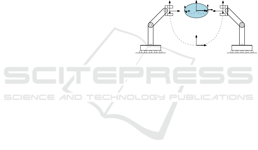
The general formulation of a dual-arm coopera-
tive manipulation task is sketched in Figure 1. Each
manipulator may have n
i
joints for a total of n = Σn
i
degrees of freedom. A common base frame with co-
ordinates {B} stands as a fixed global frame for the
combined system. Further coordinate frames are es-
tablished for the end-effectors, {E1} and {E2}, as
well as the manipulated object, {O}. The grasp points
at which each manipulator contacts the object are
known a priori, and are prescribed as constant homo-
geneous transforms in the object’s fixed frame,
O
T
G1
and
O
T
G2
. As a matter of convention, a manipulator’s
end-effector is defined as the feature which should co-
incide with one of an object’s grasp-points.
B
T
E1
{B}
{E1}
{E2}
B
T
E2
{O}
{G1} {G2}
O
T
G1
O
T
G2
Figure 1: Dual-arm cooperative manipulation scenario.
2 COORDINATED CONTROL
2.1 Coordinated Potential Field
The combined controller should retain its capacity to
direct each arm independently and allow for seamless
transition from individual to cooperative manipula-
tion. To retain independent functionality, a separate
instance of the Secant controller (Ahlin et al., 2018)
is initially assigned to each robot chain, forming the
potential fields {Ψ
1
, Ψ
2
}, where each field is config-
ured for its respective manipulator’s task-space goal.
In a cooperative task, the two fields are configured
with the same goal so that both chains act collabo-
ratively. However, further modification is required
to enforce a relative constraint between the manipu-
lators to avoid crushing, twisting, or otherwise vio-
lating the volumetric properties of a held object. To
enforce the desired cooperative kinematic constraint
between the manipulators, we define and generate a
secondary potential field Φ(z) whose task-space tar-
get is the shared object frame {O}. The gradient of
this field, evaluated at the ith end-effector, provides a
new spring force which acts in contrast to any relative
offset between the manipulators. The new, modified
gradient at the ith manipulator for APF control is cal-
culated as:
Dual-Arm Compliance Control with Robust Force Decomposition
617
∇
i
=
∂Ψ
i
(z
ai
)
∂z
+
∂Φ(z
ri
)
∂z
(1)
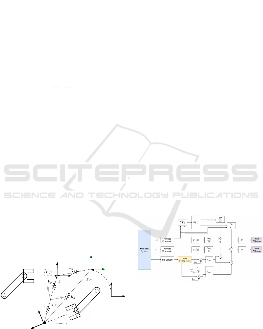
This arrangement can be understood in Figure 2. An
important consideration: this research is using the Se-
cant Method to create a trajectory in Cartesian space.
As such, dynamic effects such as gravity and Coriolis
effects do not need to be considered within the plan-
ner. These terms are accounted for in the arm con-
trollers and in the force profile read by the sensors.
2.2 Incorporating Grasp Offset
To maintain coherent robot motion in cooperative
mode, the gradients {
∂Ψ
1
∂z
,
∂Ψ
2
∂z
} should be nominally
evaluated at an identical location. This configuration
would allow each manipulator to share a final link
when invoking the inverse Jacobian, resulting in a
common center of rotation for the combined manip-
ulator. This is accomplished by establishing a virtual
Tool Center Point (vTCP) for each manipulator, de-
rived from the grasp transformation.
(
E
T
V
)
i
= (
O
T
Gi
)
−1
(2)
In this manner, the robot end-effector will nomi-
nally coincide with the grasp feature while the vTCP
will coincide with the object’s body origin. While the
vTCP is reserved as the last link in each kinematic
chain, it is excluded from all obstacle avoidance cal-
culations.
Finally, disturbances or errors may result in tran-
sitory or fixed offsets between the vTCPs, leaving
the shared object frame ambiguously defined. We re-
solve the ambiguity by approximately inferring {O}
in real-time as the average of the vTCP poses. For
the position component, this is easily computed as the
element-wise mean of both. For the orientation com-
ponent, we use the 50% quaternion spherical linear
interpretation (SLERP) between the two orientations.
(
E
T
V
)
1
(
E
T
V
)
2
z
r1
z
r2
{B}
{T }
z
a1
k
a
k
k
2
B
T
T
Figure 2: Dual-arm coordinated control.
3 COMPLIANCE CONTROL
3.1 Overview
Let a convention for generalized forces, or wrenches,
be defined:
F
x
=
f
T
x
τ
T
x
T
(3)
where the wrench is composed of a linear force f and
a torque τ applied at some point x.
Compliance can be implemented in an artificial
potential field by superimposing a new class of forces
onto the gradient of the map. The forces are con-
structed according to the laws
F
Ec
= k
E
⊙ (F
Ed
− F
E
) (4)
where k
E
is a vector of gain factors whose entries cor-
respond to each respective element of a generalized
force vector, and which are applied to a wrench via
the Hadamard product with the ⊙ operator. F
E
is the
current external wrench applied to the object and F
Ed
is the desired or commanded external wrench.
In the dual-arm condition, as in any similar coop-
erative manipulation task, an additional internal force
is introduced as an artifact of its over-constrained na-
ture. The internal force can be decomposed in a sim-
ilar manner as to the external and with the same sub-
scripted meanings:
F
Ic
= k
I
⊙ (F
Id
− F
I
) (5)
The integration of these two compliance forces
into the APF controller is detailed in Figure 3. The
subsequent sections investigate how to accurately de-
termine F
E
and F
I
.
Figure 3: Dual-arm coordinated and compliant control.
3.2 F/T Equivalence
In these operations, it is often necessary to convert
forces from one point of application to another while
maintaining an equivalent effect on the rigid body.
This requirement is most often introduced when a ma-
nipulator’s force-torque sensor does not coincide with
the tool center point, as will be the case in coopera-
tive manipulation tasks involving a volumetric object.
ICINCO 2023 - 20th International Conference on Informatics in Control, Automation and Robotics
618

The matrix transferring a spatial wrench at point α to
point β is
γ
Ω
α
=
I
3
0
3
⌊r
γ→α
×⌋ I
3
(6)
where ⌊·×⌋ forms the skew-symmetric matrix for
cross-product operations and r
γ→α
is the vector drawn
from the point γ to the point α.
Where it is necessary to perform a change of basis
from {A} to {B}, it shall be noted as x
B
=
B
β
A
x
A
.
Unless otherwise stated, we express all vectors and
wrenches in a fixed common work frame {W }.
3.3 Determining External Force
The analysis completed by (Walker et al., 1991) of a
rigid body assumes a firm grasp transmits both forces
and moments at the point of contact. Let F
gi
be the
contact forces at the ith of k total grasp points ex-
pressed in work frame coordinates. From a free-body
diagram analysis, the net force exerted externally on
the object can be expressed generally as
F
o
= W F
g
(7)
with
F
g
= [F
T
g1
, ..., F
T
gk
]
T
(8)
W =
I
3
0
3
. . . I
3
0
3
⌊r
g1
×⌋ I
3
. . . ⌊r
gk
×⌋ I
3
(9)
where W is known as the grasp matrix in the R
3
spa-
tial context, r
gi
is the vector drawn from the object
frame to the ith grasp point, and all vectors are ex-
pressed in the common work frame.
We further stipulate that the force-torque sensor
might not be coincident with the end-effector of the
robot chain. Therefore, so as to calculate forces as
applied at the sensor, we replace the vectors r
gi
with
r
si
, the vector drawn from the object frame to the ith
chain’s F/T sensor. In this way, the end-effector chain
is considered a rigid component of the grasped object,
and the net object force can be expressed as a function
of the F/T sensor readings F
ri
. In the dual-arm sce-
nario shown in Figure 4, these relationships reduce to
F
o
=
¯
W F
r
(10)
with
F
r
=
F
T
r1
F
T
r2
T
(11)
¯
W =
O
Ω
S1
O
Ω
S2
(12)
In general, the external force F
o
includes not only
external loads but also the effects of gravity and any
dynamic forces arising from the acceleration of the
body. This is observed from the sum of forces and
moments for a dynamic rigid body with constant mass
{X, Y, Z}
G1
{X, Y, Z}
G2
{X, Y, Z}
O
O
T
G1
O
T
G2
f
g1
τ
g1
f
g2
τ
g2
r
g1
r
g2
(a)
{X, Y, Z}
Ei
{X, Y, Z}
Si
(
S
T
E
)
i
(b)
Figure 4: (a) Dual-arm cooperative object detail. (b) End-
effector chain detail.
and inertial properties. However, a rigorous consider-
ation of inertial effects is not the focus of the present
investigation. We assume small acceleration and ve-
locity throughout, resulting in small dynamical terms
in comparison to external disturbances. As the in-
corporation of the dynamical terms is linear, they can
thus be neglected. We also consider the effect of grav-
ity as an external disturbance rather than accounting
for it directly, since the mass of the object is unknown.
In practice, zeroing of F
o
suffices to account for grav-
ity, and we establish:
F
E
= F
o
(13)
3.4 Determining Internal Force
Established methods in literature isolate the internal
force contribution of a given manipulator by subtract-
ing the expected wrench
¯
F
ri
in an unloaded internal
condition from the reported wrench.
F
int
= F
r
−
¯
F
r
(14)
To obtain
¯
F
r
, the authors have pre-multiplied (10)
by the inverse of the grasp matrix to isolate F
r
. How-
ever, in over-constrained systems, the grasp matrix
has a nonzero null space and cannot be inverted ex-
cept approximately by a pseudoinverse, as investi-
gated in (Walker et al., 1991). These linear ap-
proximations are merely mathematical optimizations
rather than informed studies, resulting in poor accu-
racy along certain axes.
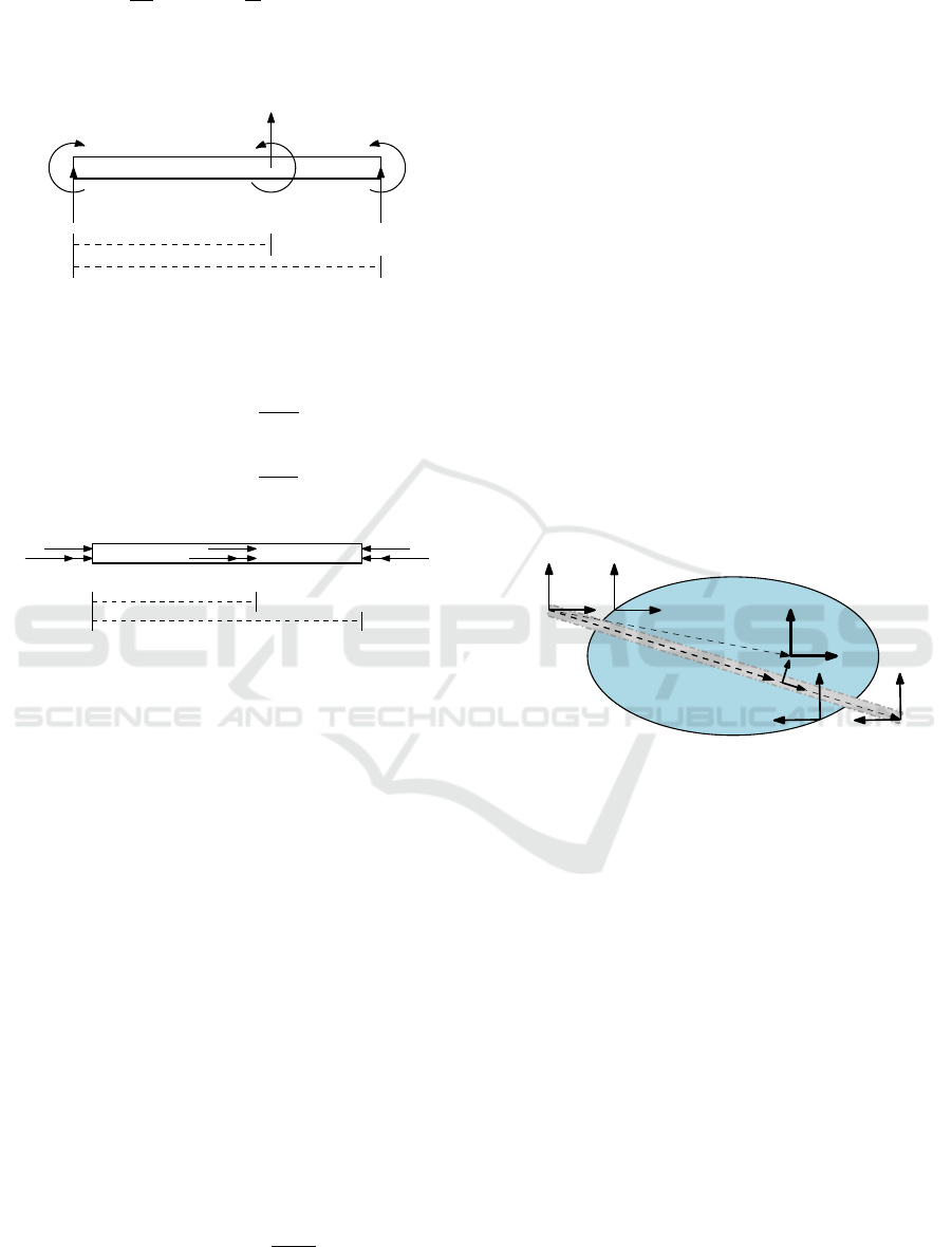
Rather than make use of a pseudoinverse, we pro-
pose modeling the handled object as a statically inde-
terminate beam. This model assumes the object has
a fairly uniform cross-section and structural stiffness.
In the case of transverse forces and moments (Fig-
ure 5), the one-dimensional reactionary wrench at the
constraint a units away from the external wrench ap-
plication upon a beam of length l can be calculated
according to (Roark et al., 2012).
R
T,a
( f , τ) =
− f
l
3
(l − a)
2
(l + 2a) +
6τa
l
3
(l − a) (15)
Dual-Arm Compliance Control with Robust Force Decomposition
619
M
T,a
(t, τ) =
f a
l
2
(l − a)
2
+
τ
l
2
(l
2
− 4al + 3a
2
) (16)
where R is the linear reactionary force, M is the reac-
tionary torque, f is the load force, and τ is the load
torque.
R
a
M
a
R
b
M
b
a
l
f
τ
Figure 5: Statically indeterminate beam (transverse forces).
The longitudinal case (Figure 6) may be similarly
calculated (Hibbeler, 2011).
R
L,a
( f ) = f
a − l
l
(17)
M
L,a
(τ) = τ
a − l
l
(18)
R
a
M
a
R
b
M
b
a
l
f
τ
Figure 6: Statically indeterminate beam (longitudinal
forces).
The question now arises as to which physical
points should be associated with the ends of the mod-
eled beam, or beam phantom. An intuitive option is
to define the beam phantom as the line joining the two
grasp points. However, the end-effector chains them-
selves can be seen as forming part of a larger rigid
body containing the shared object. Here, the nuances
of the manipulation problem can become more rele-
vant, such as the comparative stiffness of the object
and end-effector chain. We proceed with a method
based on the second observation and assume a more
accurate model admits to the entire structure con-
tributing to the combined deformation effects. The
force-torque sensors of either arm shall be the termi-
nation points of the beam phantom, with the span of
the vector g joining them termed the grasp line (Fig-
ure 7).
The phantom point of force application {
˜
O} is de-
fined by orthogonal projection of the object origin
onto the grasp line. In this way, the equivalent offset
a is maintained, which is critical for model validity.
r
˜o
= Proj
g
(r
o
) =
g
T
r
o
r
T
o
r
o
r
o
(19)
{a, l} = {||r
˜o
||, ||g||} (20)
where r
o
is the vector drawn from the F/T sensor of
manipulator 1 to the shared object center O. Addition-
ally, {
˜
O} is oriented so as to always align its x-axis
with the longitudinal axis of the beam. Since internal
forces do not affect object motion and thus do not ap-
pear in the net object force F
o
, the result of (10) may
be used for the purpose of calculating the expected
wrenches in the internally unloaded condition. The
object force is transferred to {
˜
O} by F/T equivalence,
and then expressed in the coordinates of {
˜
O}, allow-
ing systematic application of the beam equations with
resultant wrenches
˜
F
r
expressed in the same frame.
F
˜o
=
˜
O
β
W
˜
O
Ω
O
F
o
(21)
˜
F
r1
=
R
L,a
(f
˜o
·
ˆ
i)
R
T,a
(f
˜o
·
ˆ
j, τ
˜o
·
ˆ
k)
−R
T,a
(−f
˜o
·
ˆ
k, τ
˜o
·
ˆ
j)
M
L,a
(τ
˜o
·
ˆ
i)
−M
T,a
(−f
˜o
·
ˆ
k, τ
˜o
·
ˆ
j)
−M
T,a
(f
˜o
·
ˆ
j, τ
˜o
·
ˆ
k)
(22)
where
ˆ
i,
ˆ
j,
ˆ
k are the unit identity vectors. Note that, in
practice, care must be taken to properly account for
sign differences caused by the coordinate convention.
{O}
{S1}
{
˜
O}
r
o
r
˜o
g
{S2}
{G1}
{G2}
Figure 7: Statically indeterminate beam phantom.
It is desirable to compute compliance in the
object-fixed frame. This permits, for instance, a con-
stant squeeze force along a particular axis of the ob-
ject, regardless of its orientation or that of the end-
effectors with respect to it. Therefore, before the gain
factors are applied,
˜
F
ri
is transferred to and expressed
in the original object frame, {O}.
¯
F
r1
=
O
β
W
O
Ω
˜
O
W
S
˜
O
˜
F
r1
(23)
Note that it has not been necessary to perform
identical calculations on the second manipulator. This
is because, by definition, internal forces do not con-
tribute to object motion. If the internal forces con-
tributed by the ith manipulator are transferred to and
expressed in the same frame, then
Σ
¯
F
Ii
= 0 (24)
Since there are only two manipulators, this expands
to
¯
F
I1
= −
¯
F
I2
(25)
The internal gain factors k
I
are applied and the results
expressed in work frame coordinates.
ICINCO 2023 - 20th International Conference on Informatics in Control, Automation and Robotics
620
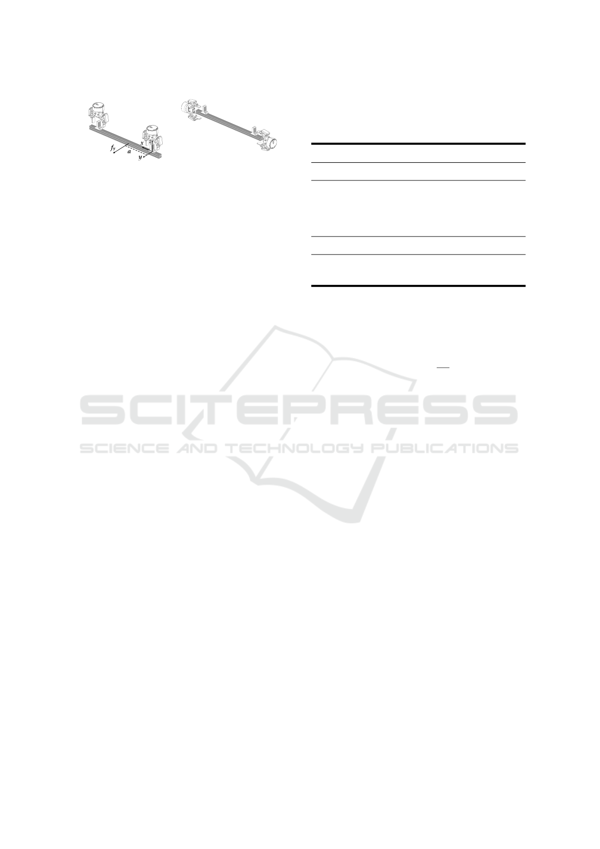
(a) (b)
Figure 8: (a) Experiment upright posture. (b) Experiment
horizontal posture.
4 FORCE DECOMPOSITION
EXPERIMENTS
To illustrate the advantage of our beam method, static
experiments are performed on a mock object manip-
ulation problem. The object is a 1” aluminium ex-
trusion and is grasped by 2-finger grippers with ap-
proximately 470 mm of separation. F/T readings are
recorded by an ATI Axia80 placed in the end-effector
chain of one of the manipulators. It should be men-
tioned that the finger grippers will always provide
forces, but due to their relatively small contact sur-
face, may not provide reactionary torques along all
axes. To help determine the true boundary condi-
tions, two different grasp postures are evaluated (Fig-
ure 8). The upright posture minimizes the gripper
surface area that would contribute a torque in the z-
axis, while the horizontal posture maximizes it. Lin-
ear force along the y-axis and torque along the z-axis
are independently applied at seven different points
along the beam. The measured F/T response is com-
pared to the expected values yielded by the Moore-
Penrose pseudoinverse (PINV), the No-Squeeze pseu-
doinverse (Walker et al., 1991), our beam method,
and a simply-supported (SS) model. The simply-
supported model assumes the grippers transmit no
torque; by removing the torque entries of F
r
, the
grasp matrix W becomes square with a unique non-
approximate inverse. As anticipated, the simply-
supported model best predicts experimental F/T read-
ings in the upright configuration; however, our beam
method provides substantial improvements in the hor-
izontal posture, as shown in Table 1.
First, it is noted that the beam and pseudoinverse
predictions for f
r
in response to a linear force con-
verge when the point of force application is near
the geometric center of beam. In this regard, the
beam method provides the greatest advantage when
the shared object has a center of gravity which does
not coincide with its volumetric center, or when it has
an off-center interface point with the environment.
The experiments yield one modification that must
be made: both manipulators share equally the load in-
Table 1: Minimum and maximum F/T sensor prediction er-
ror ϵ, as a percentage of |F
ext
|, in response to a static load
applied at a range of locations ±20% of the distance be-
tween the sensors in the horizontal posture. Lower is better.
Isolated Force
ϵ PINV No-Squeeze SS Beam
f
r
1.5—31 2.6—36 1.9—17 0.9—8.7
τ
r
2.4—30 3.3—33 5.7—22 0.0—5.1
Isolated Torque
ϵ PINV No-Squeeze SS Beam
f
r
88—140 110—160 19—74 6.5—47
τ
r
64—81 76—92 26—42 5.2—31
duced by a linear force applied longitudinally along
the beam (that is, along the denoted x-axis), regard-
less of where it is applied. While the beam method
theory is in disagreement, it is simple to revise it to
accommodate:
R
′
L,a
( f ) = f
−1
2
(26)
5 LIVE APPLICATION ANALYSIS
A typical benchmark for manipulation tasks is the
peg-in-hole problem, serving as a primary primitive
for applied multi-axis compliance in insertion con-
texts. To benchmark our dual-arm system with im-
proved force decomposition, we design a peg-in-hole
problem (Figure 9) in which both internal and exter-
nal compliance are required along a transverse axis.
Internal compliance may be necessary when the ex-
pected and actual object geometries do not match,
which we simulate by using object handles mis-
aligned by about 40 mm. To highlight the advantage
of the beam method, the mating point is located non-
centrally between the two manipulators, at a point
20% along the total length. To demonstrate external
compliance, the mating peg location is erroneously
perturbed, and a large 45
◦
chamfer is added to the peg
sockets to lengthen the distance over which compli-
ance is employed. Additionally, the use of two sepa-
rate mating features provide a rotational constraint to
demonstrate both linear and angular responses. The
mating point is taken as the center-point between the
two features.
Our dual-arm system is comprised of two UR5e
collaborative robot arms, each attached to a respective
rail carriage to form a total of 14 DoF. The rail car-
riages are individually powered by Parker-Hannifin
Dual-Arm Compliance Control with Robust Force Decomposition
621
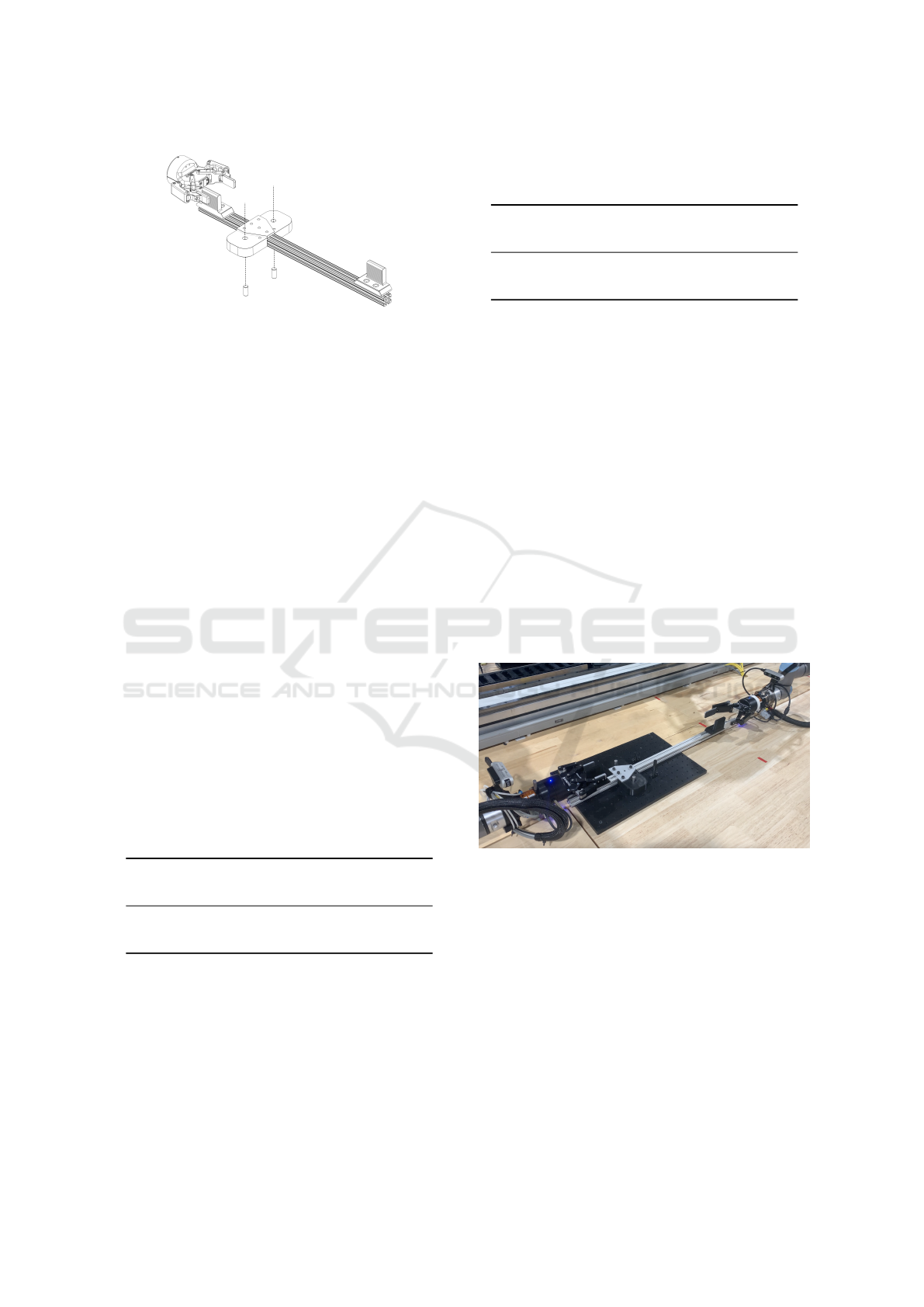
Figure 9: Aluminium extrusion with misaligned handles
and two peg sockets. Beam length is not to scale in this
sketch.
IPA04-HC motor controllers. F/T readings for each
manipulator are obtained using the internal UR5e sen-
sors. Manipulator 1 uses a Robotiq 2F-85 gripper, and
manipulator 2 uses a longer 2F-140 model. To ensure
the transmission of torque at the grasp points, the ob-
ject is grasped in a horizontal posture.
5.1 Isolated Force Application
We simulate the interactions between the peg and hole
by applying a transverse force f
y
at the mating point.
The metrics of interest are the reported internal force
f
int,y
and torque τ
z
. Since only an external force is
in fact being applied during the experiment, f
int,y
and
τ
int,z
should remain constant. For completeness, this
experiment is performed twice, once with external
control enabled and again with it disabled. When
enabled, the same control gains are used across the
tested force decomposition methods. It is noted that
the baseline internal force caused by gripping the mis-
aligned handles varies depending on the force decom-
position method employed. This is accounted for by
subtracting the prior baseline reading before analysis.
Table 2: Maximum internal force and torque in response to
a simulated peg-in-hole interaction with the Beam method
and control disabled. Lower is better.
Component Method
(as % of |F
ext
|) PINV No-Squeeze Beam
Linear, f
int
15 16 0.8
Torque, τ
int
13 15 4.1
From Tables 2 and 3, it is clear that the beam
method provides an improvement in registered inter-
nal loading in all conditions, with maximum benefit
when the control gains are lowest (emulated at the
limit by disabled control). Improvements over the
Moore-Penrose pseudoinverse are maximum at 18x
in linear force and 3x in torque. Against the No-
Squeeze method, the Beam technique offers maxi-
mum improvements of 15x in force and 3x in torque.
Table 3: Maximum internal force and torque in response to
a simulated peg-in-hole interaction with the Beam method
and control enabled. Lower is better.
Component Method
(as % of |F
ext
|) PINV No-Squeeze Beam
Linear, f
int
3.5 4.5 1.1
Torque, τ
int
10 20 5.9
5.2 Peg-in-Hole Demonstration
The complete system is run on actual hardware with
control enabled. The purpose of the demonstration is
to show the collective functioning of the planner and
compliance technique in the real-world context of a
mating problem. Figure 9 is a still frame from the
demonstration recording. The demonstration success-
fully mates the rotationally constrained object with an
initial error neighboring 6
◦
in rotation and 2.5cm in
vertical distance. The direct-contact insertion phase
completes in approximately five seconds. Greater er-
ror could be tested using larger socket chamfers. Os-
cillations are present once both pegs fully thread into
the sockets, particularly along the axis of the rail car-
riages. This is a stability problem associated with the
force impulses upon contact with a rigid surface. Re-
ducing the force response gain and increasing posi-
tional stiffness alleviates these oscillations.
Figure 10: Dual peg-in-hole demonstration.
6 CONCLUSION
Coordinated dual-arm control of a shared object has
been achieved using a modified artificial potential
field controller as the basis for path planning. For
demonstration, the system was able to solve an an-
gularly constrained, non-central peg-in-hole prob-
lem. Future work may involve demonstrating static
and dynamic object collision avoidance, leveraging
the novel capabilities of the Secant Method. More-
over, compliance has been incorporated into the con-
troller using a physically driven nonlinear model. Our
ICINCO 2023 - 20th International Conference on Informatics in Control, Automation and Robotics
622

method of force decomposition achieves better re-
sults in experiment, up to an order of magnitude, than
common methods in literature. Future improvements
to the technique could include modeling interaction
torques as a force-couple with known moment arm
rather than a concentrated torque; this would match
the physical scenario more closely in certain config-
urations. Internal compliance might also be adjusted
so as to use each manipulator’s gripper point as the
respective center of rotation, while still sharing the
object center for external compliance and object-level
trajectory planning. Object mass and inertia proper-
ties, neglected here, could be incorporated into the
equations of motion. A Kalman filter could be ex-
plored for smoothing reactions to impulsive contact
forces and reducing oscillations. Taken together, this
work forms the basis for future dual-arm collabora-
tive object manipulation, including the exploration of
intelligent insertion strategies to improve speed and
repeatability.
REFERENCES
Ahlin, K. J., Sadegh, N., and Hu, A.-P. (2018). The se-
cant method: Global trajectory planning with variable
radius, solid obstacles. In Dynamic Systems and Con-
trol Conference, volume 51913, page V003T32A015.
American Society of Mechanical Engineers.
Calanca, A., Muradore, R., and Fiorini, P. (2016). A re-
view of algorithms for compliant control of stiff and
fixed-compliance robots. IEEE/ASME Transactions
on Mechatronics, 21(2):613–624.
Erhart, S. and Hirche, S. (2015). Internal force analysis and
load distribution for cooperative multi-robot manipu-
lation. IEEE Transactions on Robotics, 31(5):1238–
1243.
Gao, M., Zhou, H., Yang, Y., Dong, Z., and He, Z. (2022).
An intelligent master–slave collaborative robot system
for cafeteria service. Robotics and Autonomous Sys-
tems, 154:104121.
Hibbeler, R. C. (2011). Mechanics of materials. Prentice
Hall, Boston, 8th ed edition.
Hu, B., Yan, L., Han, L., and Yu, H. (2021). Coordinated
compliance control of dual-arm robot astronaut for
payload operation. International Journal of Advanced
Robotic Systems, 18(3):17298814211012850.
Khatib, O. (1985). Real-time obstacle avoidance for manip-
ulators and mobile robots. In Proceedings. 1985 IEEE
international conference on robotics and automation,
volume 2, pages 500–505. IEEE.
Khatib, O. (1986). The potential field approach and opera-
tional space formulation in robot control. pages 367–
377. Springer.
Kim, R., Balakirsky, S., Ahlin, K., Marcum, M., and
Mazumdar, A. (2021). Enhancing payload capacity
with dual-arm manipulation and adaptable mechani-
cal intelligence. Journal of Mechanisms and Robotics,
13(2).
Kousi, N., Michalos, G., Aivaliotis, S., and Makris, S.
(2018). An outlook on future assembly systems in-
troducing robotic mobile dual arm workers. Procedia
CIRP, 72:33–38. 51st CIRP Conference on Manufac-
turing Systems.
LaValle, S. M. (2006). Planning algorithms. Cambridge
university press.
Omar, R., Sabudin, E., CK, C. K. M., et al. (2016). Po-
tential field methods and their inherent approaches for
path planning. volume 11, pages 10801–10805. Asian
Research Publishing Network (ARPN).
Ren, X., Huang, L., and Zhao, M. (2021). Prioritized hier-
archical compliance control for dual-arm robot stable
clamping.
Roark, R. J., Young, W. C., Budynas, R. G., and Sadegh,
A. M. (2012). Roark’s formulas for stress and strain.
McGraw-Hill, New York, 8th ed edition. OCLC:
ocn769455976.
Seraji, H. (1994). Adaptive admittance control: an approach
to explicit force control in compliant motion. In Pro-
ceedings of the 1994 IEEE International Conference
on Robotics and Automation, pages 2705–2712 vol.4.
Song, X., Huang, H., Xu, W., and Li, B. (2022). A ro-
bust force controller of multi-robot cooperative ma-
nipulators for carrying task. In 2022 IEEE Interna-
tional Conference on Robotics and Biomimetics (RO-
BIO), pages 987–992, Jinghong, China. IEEE.
Song, X., Mao, H., Huang, H., Xu, W., and Li, B. (2021).
A Dynamic Adaptive Impedance Controller for Force
Tracking of Dual-arm Manipulators in Uncertain Con-
tact Environment. In 2021 IEEE International Con-
ference on Robotics and Biomimetics (ROBIO), pages
1674–1681, Sanya, China. IEEE.
Walker, I. D., Freeman, R. A., and Marcus, S. I. (1991).
Analysis of Motion and Internal Loading of Ob-
jects Grasped by Multiple Cooperating Manipula-
tors. The International Journal of Robotics Research,
10(4):396–409.
Wolf, S., Grioli, G., Eiberger, O., Friedl, W., Grebenstein,
M., Hoppner, H., Burdet, E., Caldwell, D. G., Car-
loni, R., Catalano, M. G., Lefeber, D., Stramigioli,
S., Tsagarakis, N., Van Damme, M., Van Ham, R.,
Vanderborght, B., Visser, L. C., Bicchi, A., and Albu-
Schaffer, A. (2016). Variable stiffness actuators: Re-
view on design and components. IEEE/ASME Trans-
actions on Mechatronics, 21(5):2418–2430. Cited By
:266.
Xian, Z., Lertkultanon, P., and Pham, Q.-C. (2017). Closed-
chain manipulation of large objects by multi-arm
robotic systems. IEEE Robotics and Automation Let-
ters, 2(4):1832–1839.
Dual-Arm Compliance Control with Robust Force Decomposition
623
