
Simulating a Novel SIW Bow-Tie Antenna and Comparing Return
Loss and Gain Performance with SIW Slot Antenna for X Band
Applications
Sanju Priya B. R. and Anitha G.
Department of Electronics and Communication Engineering, SIMATS, Thandalam, Chennai, 602 105, India
Keywords: Novel SIW Bow-Tie Antenna, SIW Slot Antenna, Gain, HFSS, Return Loss, Communication Technology.
Abstract: To compare the performance of Bow-Tie shaped SIW antenna with the SIW Slot antenna in terms of return
loss and gain running at 10 GHz on 50-ohm characteristics impedance. Return loss and gain on 50 Ω
characteristic impedance for SIW Bow-Tie antenna (n=27) and SIW Slot antenna (n=27). SIW Bow-Tie
antenna (Return loss: -31.9265 dB, Gain: 4.57 dBi) outperforms SIW Slot antenna (Return loss: -27.0050 dB,
VSWR: 2.0 dBi). SIW Bow-Tie antenna and SIW slot antenna have ideal proportions of 19.8mm x 16.8mm.
The Independent sample test between both groups (SIW Bow-Tie antenna and SIW Slot antenna) achieved a
significance value p=0.036 (p<0.05) for return loss and p =0.000 (p< 0.05) for gain, indicating a significant
dissimilarity amongst the two antennas. The gain and return loss of the novel Bow-Tie shaped SIW Antenna
are higher than that of the SIW Slot Antenna.
1 INTRODUCTION
The intention of the analysis study is to simulate using
HFSS software and assess the return loss and gain
performance of a SIW Bow-Tie antenna and SIW slot
antenna running at 10 GHz on 50-ohm characteristics
impedance. Bow-Tie antennas were employed to
increase performance by providing a lower return loss,
a flatter input impedance, and a steadier radiation
pattern. Bow-tie slot antennas are suitable choices for
larger bandwidth and easy planar antenna construction
(Kaur and Solanki 2012). Bow tie
shaped antenna provide several of positive aspects,
notably slim profile, ease in layout and manufacture,
better radiation symmetry, planar construction, and
condensed dimensions than others (L. Liu et al. 2018).
SIW technology was created as a replacement for
large metallic waveguides. Using this method, a
hollow space may be built on flat plane surfaces. As a
result, microwave circuits, which previously required
a massive metallic waveguide, shrank significantly in
size. Despite having a larger loss than typical metal-
containing waveguides, these provide adequate
functionality for an extensive variety of antenna
operations and tiny filter types (Varnoosfaderani, Lu,
and Zhu 2014). One potential contender for extended-
range spatial coverage is the Antenna with a bow tie
built around SIW technique. At 24 GHz, the antenna
is ideal for limited range vehicle radar-related uses
(Abhay Kumar and Srivastava 2021). Applied to the
KU and X bands (Maruti, Maruti, and Naga Kishore
2022). Ground-penetrating radar (GPR) Applications
(Nayak and Maiti 2019). Tri-Band Applications (H.
Liu et al. 2013) and UWB (ultra-wideband)
applications (Sayidmarie and Fadhel 2013). For
broadband applications, the BTCRS (Bow-tie-
complementary-ring-slot) antenna replaces the
conventional wire bowtie antenna (Arvind Kumar and
Raghavan 2018). Point-to-point interfaces, which are
similar to local area networks (LAN), are one of the
MMW spectrum's applications. Broadband and high-
definition TV in the Ka (MMW) band have been
employed to provide people with high-quality
government services. In addition, radars with
excellent precision and resolution are utilised in this
frequency spectrum for uses in sensing. These kinds
of uses can be realised with the use of an appropriate
antenna, such as the SIW Antenna (Oliaei and
Abrishamian 2020).
Cited Articles and Their Findings
Several academic articles on SIW Bow-Tie antennas
were published during the previous five-year period.
IEEE Xplore published 9 papers on research, but
Google Scholar released 15,100. A redesigned bow-
tie antenna (Dadgarpour et al. 2015) configuration is
presented for good gain performance at frequencies
B. R., S. and G., A.
Simulating a Novel SIW Bow-Tie Antenna and Comparing Return Loss and Gain Performance with SIW Slot Antenna for X Band Applications.
DOI: 10.5220/0012602700003739
Paper published under CC license (CC BY-NC-ND 4.0)
In Proceedings of the 1st International Conference on Artificial Intelligence for Internet of Things: Accelerating Innovation in Industry and Consumer Electronics (AI4IoT 2023), pages 13-19
ISBN: 978-989-758-661-3
Proceedings Copyright © 2024 by SCITEPRESS – Science and Technology Publications, Lda.
13

ranging from 57 to 64 GHz. The antenna is made up of
two tilted bow-tie radiators, one on each end of a
shared dielectric base, and is supplied by a
SIW feedline. The bow-tie emitters are crossed
symmetrically to maximise the gain of the antenna and
achieve the desired emission distribution. Over the
frequency band of 57-64 GHz, the antenna has a
calculated gain of 11.5- 12 dBi and an apparent
reflection factor of less than -11 dB. The suggested
antenna is easy to develop and cheap to build. The
properties of the antenna make it appropriate for usage
in 60 GHz interior wirelessly communication
technology systems. The intent of the current study
(Althuwayb 2021) is to develop a novel slot bowtie
antenna design working from 30 GHz to 37 GHz that
is suitable for the lower frequency range of the 5G
millimeter-wave region. A bowtie arrangement was
formed by creating two trapezius-shaped slots in
sequence. It is proved that a wide frequency
bandwidth with good radiation performances may be
achieved utilising the MTM (metamaterial) and SIW
(substrate integrated waveguide) concepts with no
loss of the material properties. A revolutionary
approach for generating dual bands in technology of
SIW is provided and thoroughly examined in (Nandi
and Mohan 2016). The architecture is versatile since
each of these mixed-mode frequency resonances may
be modified independently. To create the second band,
both the second and the third combined resonating
frequencies of this dual-band antenna were adjusted
moved nearer together. To keep the antenna low
profile, it is built on a single substrate layer and fed by
a basic GCPW (grounded coplanar waveguide)
approach. Furthermore, the suggested antenna has a
modest gain and a broadband response in both bands,
making it suitable for a variety of dual-band practical
applications in the X-band. The designed SCPBTA's
(self-complementary planar bow-tie antenna)
experimental and numerical performance parameters
in both the time and frequency domains have been
given and discussed in (Sayidmarie and Fadhel 2013).
In comparison to a variety of recent designs disclosed
in the open literature, the suggested antenna is simpler
in construction and manufacturing, while providing a
broader bandwidth and a lower footprint. The results
suggest that the SCPBTA is a capable choice for usage
in UWB (ultra-wideband) communication or phased
array systems. According to the results of the studies
(Tan et al. 2014), the highest frequency tuning range
of ferrite-loaded the SIW cavity-backed bowtie slot
antennas is 1460 MHz. In the meantime, the antenna's
pattern of radiation and gain fluctuate slightly with
tuning, showing robust radiation performance for
practical applications. The antenna's design has the
advantages of affordability, slim profile, ease
in integration with planar circuits, and ease of
manufacture, and it may be utilised in wireless
transmission platforms such as radar and
communications via satellites. The primary
disadvantage of the antenna with SIW Slot is that it
has a lower gain and return loss than the novel SIW
Bow-Tie Antenna. Many studies have been carried out
in order to improvise the gain and return loss of the
SIW antennas. An antenna's return loss and gain
characteristics can be enhanced by adjusting the patch
design's location and pattern. At 10 GHz input
frequency, this article analyzes the gain and return loss
characteristics of a unique SIW Bow-Tie antenna with
a SIW Slot antenna.
2 MATERIALS AND METHODS
The analysis is being conducted in the VLSI
Laboratory at Saveetha School of Engineering's
Department of Electronics and Communication
Engineering. A total of two groups were formed. Each
category has a total of 27 samples. The overall count
of participants is 54. When doing evaluations and with
one as the enrollment ratio, the pre-test power for
continuous testing is 80%. The alpha and beta values
in the proposed study are 0.05 and 0.2 respectively
(Rosner 2015).
For this study, two different preparation procedures
were implemented. In Group 1, SIW Bow Tie Antennas
were created and simulated using HFSS software. A
Bow Tie Antenna has been designed and built using
Substrate Integrated Waveguide (SIW) technology.
The dimensions and specifications of the Ground, a
Substrate on the top, with a Patch, and a Feed with a
Feedline, and dimensions of the Patch were modified
according to the parameters in Table 1.
Group 2 followed the same preparation procedures
as Group 1. In Group 2, SIW Slot antenna was
constructed and analyzed using HFSS software. A
SIW Slot Antenna has been designed and built using
Substrate Integrated Waveguide (SIW) technology.
The measurements of Ground, a Substrate on the top,
with a Patch, and a Feed with a Feedline, and
dimensions of the Patch were modified according to
the parameters in Table 1.
HFSS is a highly effective full-wave EM field
emulator 3D geometric inert equipment modelling
programme that runs on Windows by Microsoft. It
combines modelling, representation, structural
modelling, and automation into a simple user interface.
Package modelling, PCB board modelling, EMC/EMI,
and antenna mobile communications are all common
AI4IoT 2023 - First International Conference on Artificial Intelligence for Internet of things (AI4IOT): Accelerating Innovation in Industry
and Consumer Electronics
14

applications. Through the evaluation technique, Return
Loss and Gain of the innovative SIW Bow-Tie and SIW
Slot antennas are computed. While testing both the
return loss and gain, keep the frequency at 10 GHz.
Combine the values from the results data together.
SPSS, which stands for statistical package for the social
sciences is a grouping of software products. The
principal use of this programme is to analyse scientific
data related to social science. The results of this analysis
might be used in market analysis, polls, information
extraction, and other ways. SPSS saves and classifies
the data entered before synthesising the data collection
to generate suitable output. SPSS is designed in such a
manner that it can handle a wide range of variable data
types.
To complete the project, Windows 11, an i5 8th
edition CPU, and HFSS modelling and evaluation
technologies were employed. To obtain the findings,
start Ansys HFSS and create an entirely novel layout
as shown in (Madhav et al. 2011). Create a substrate
over the ground, a patch above it, and a Bow-Tie
design in the patch using the specifications in Table 1.
Construct a patch feed. Choose the material of the
substrate as Rogers RT/duroid 5880. Make a shield for
radiation around the antenna. Give the spacing and
diameter of the holes. Set the excitement to the feed.
Start the analysis. Examine the results and the model.
The mentioned procedure is utilised to make Group
2’s samples by just changing the patch’s pattern as of
Table 2 results.
3 RESULTS AND DISCUSSION
Figure 1: (a) Proposed Bow-Tie shaped SIW Antenna; (b)
SIW Slot Antenna.
The novel SIW Bow-Tie antenna and the SIW Slot
antenna's Return Loss and Gain were effectively
tested and explored on 50 Ω various impedance
characteristics at 10 GHz. The settings direct the input
testing procedure. The outcome is produced by the
allocation of boundary and excitation. The output of
the graph has been saved to an Excel spreadsheet.
This file is then opened in SPSS for evaluation of
the data. Work components and procedures that have
been suggested leads to improved worker efficiency.
Tables 2 and 3 compare the Gain and Return Loss
of the novel SIW Bow-Tie and SIW Slot antennas at
10 GHz. Through the comparison from the tables, the
SIW Bow-Tie antenna has a better Return Loss (-
31.9265) and gain (4.57). The SIW Slot antenna has a
less return loss (-27.0050) and gain (2.0) than the SIW
Bow-Tie antenna. As a result, the novel SIW Bow-Tie
antenna is well established for X band applications.
The Table 4 shows that the SIW Bow-Tie antenna has
a higher mean (9.6115) than the SIW Slot antenna
(7.5996) for Return Loss. When compared to the SIW
Bow-Tie antenna (4.5700), the SIW Slot antenna
(2.0000) has a low mean gain. Compared to the SIW
Bow-Tie antenna (7.75448), SIW slot antenna
(8.32783) has higher standard deviation for return
loss. SIW slot antenna (1.60269) has higher standard
error mean than the SIW Bow-Tie antenna (1.49235)
for return loss. Both the mean deviation and the
average mean of SIW Bow-Tie antenna and SIW slot
antenna is .00000 for return loss and gain. The Table
5 uses T-test of independent samples to compare the
SIW Bow-Tie antenna to the SIW Slot antenna at 10
GHz frequency. The difference of mean for Return
Loss is 2.01189, whereas the difference of standard
error is 2.18992. While gain has a difference of mean
2.57000 and difference of standard error of .00000,
with most significant in return loss p value is 0.036
and Gain’s p-value is 0.000 (p<0.05). Hence this
article is beneficial.
Fig. 1 and Fig. 2 shows the top and front views of
the SIW Bow-Tie and SIW Slot antennas,
respectively. Fig. 3 and Fig. 4 show the return loss and
gain of Bow-Tie shaped SIW antenna. Fig. 5 and Fig.
6 show the SIW Slot antenna's return loss and gain.
Fig. 7 shows the comparison between Return Loss of
the SIW Bow-Tie and SIW Slot antenna. In the forms
of gain and return loss, Fig. 8 compares the Bow-Tie
shaped SIW antenna to the SIW Slot antenna. As a
result, the Bow-Tie shaped SIW Antenna has a higher
return loss and larger gain than the SIW Slot Antenna.
3.1 Discussion
The SIW Bow-Tie and SIW Slot antennas' return loss
and gain performance are implemented and evaluated.
According to several experiments, the novel SIW Bow-
Tie antenna beats the SIW Slot antenna in regards of
Gain and Return Loss. This data is recorded in an excel
file and will be analyzed further with SPSS software.
Simulating a Novel SIW Bow-Tie Antenna and Comparing Return Loss and Gain Performance with SIW Slot Antenna for X Band
Applications
15

Table 1: Bow-Tie shaped SIW antenna’s dimensions and
SIW Slot antenna. (Inner patch’s length and width of Bow-
Tie shaped SIW antenna: 12.95 x 8.57 mm
2
).
Parameters
SIW Bow-Tie values
SIW slot values
Resonance frequency
10 GHz
10 GHz
Substrate material
Rogers RT/duroid
5880
Rogers RT/duroid
5880
Substrate length (L
sub
)
19.8 mm
19.8 mm
Substrate width (W
sub
)
16.35 mm
16.35 mm
Thickness of Substrate
0.5 mm
0.5 mm
Ground plane Length
(L
g
)
19.8 mm
19.8 mm
Ground plane Width
(W
g
)
14.3 mm
14.3 mm
Patch width (W
p
)
14.3 mm
14.3 mm
Patch length (Lp)
19.8 mm
19.8 mm
Feed Length
1.45 mm
1.45 mm
Feed width
0.5 mm
0.5 mm
Feedline length
1.45 mm
1.45 mm
Feedline width
5 mm
5 mm
Gap of feedline
0.7 mm
0.7 mm
Inner Patch Length
12.95 mm
16.5 mm
Inner patch Width
8.57 mm
0.1 mm
Hole Diameter
1 mm
1 mm
Gap between Hole
1 mm
1 mm
Technique of Feed
Line Feed
Line Feed
Table 2: Antenna Performance of SIW Bow-Tie antenna
(Return Loss: -31.9265 dB).
Feeding Technique
Return loss (dB)
Gain (dBi)
VSWR
Microstrip Line
Feed
-31.9265
4.57
1.05
Table 3: Antenna Performance of SIW Slot antenna (Return
Loss: -27.0050 dB).
Feeding
Technique
Return loss (dB)
Gain (dBi)
VSWR
Microstrip Line
Feed
-27.0050
2.0
1.09
This paper compares and analyzes the SIW Bow-
Tie Antenna and SIW Slot Antenna into 50-ohm
characteristic impedance at 10 gigaherrtz. To support
my results this paper by (Barik et al. 2020) depicts that
return loss of the bowtie antenna is -28.58 dB and a
gain of 5.77 dB with an input frequency of 6.62 GHz.
The study that opposes my article is (Gan, Tu, and Xie
2018) which states that to achieve a better return loss
there needs to be a high frequency, The results
according to the article published have a Return Loss
value of -26.47 dB and Gain value of 5 dBi with a
frequency of 45.5 GHz. The proposed work has a
reduced Return Loss value of -31.9265 dB and a Gain
performance of 4.57, that is superior to (Fernández-
Bolaños et al. 2010), (Chen et al. 2022), (Robbins and
Bowers 1978; Zabow, Dodd, and Koretsky 2021).
Biconical antennas, particularly bowtie antennas,
have low transmission efficiency at low frequencies.
In RF sniffing or RF signal detection, a bowtie antenna
is not as effective as a complete biconical antenna.
Traditional bow-tie antennas have problems such as
end-fire evaluations, limited connectivity, scattering
properties, inefficient performance, and effectiveness.
The introduction of numerous types of metamaterials
into the antenna patch may aid biological applications
in the future.
Table 4: Descriptive analysis of SIW Bow-Tie antenna (N=27, Mean: 9.6115) and SIW Slot antenna (N=27, Mean: 7.5996).
Parameters
Type
N
Mean
Std.Deviation
Std. Error Mean
RETURN LOSS
Bow tie Antenna
27
9.6115
7.75448
1.49235
SIW slot antenna
27
7.5996
8.32783
1.60269
Gain
Bow tie Antenna
27
4.5700
.00000
.00000
SIW slot antenna
27
2.0000
.00000
.00000
AI4IoT 2023 - First International Conference on Artificial Intelligence for Internet of things (AI4IOT): Accelerating Innovation in Industry
and Consumer Electronics
16
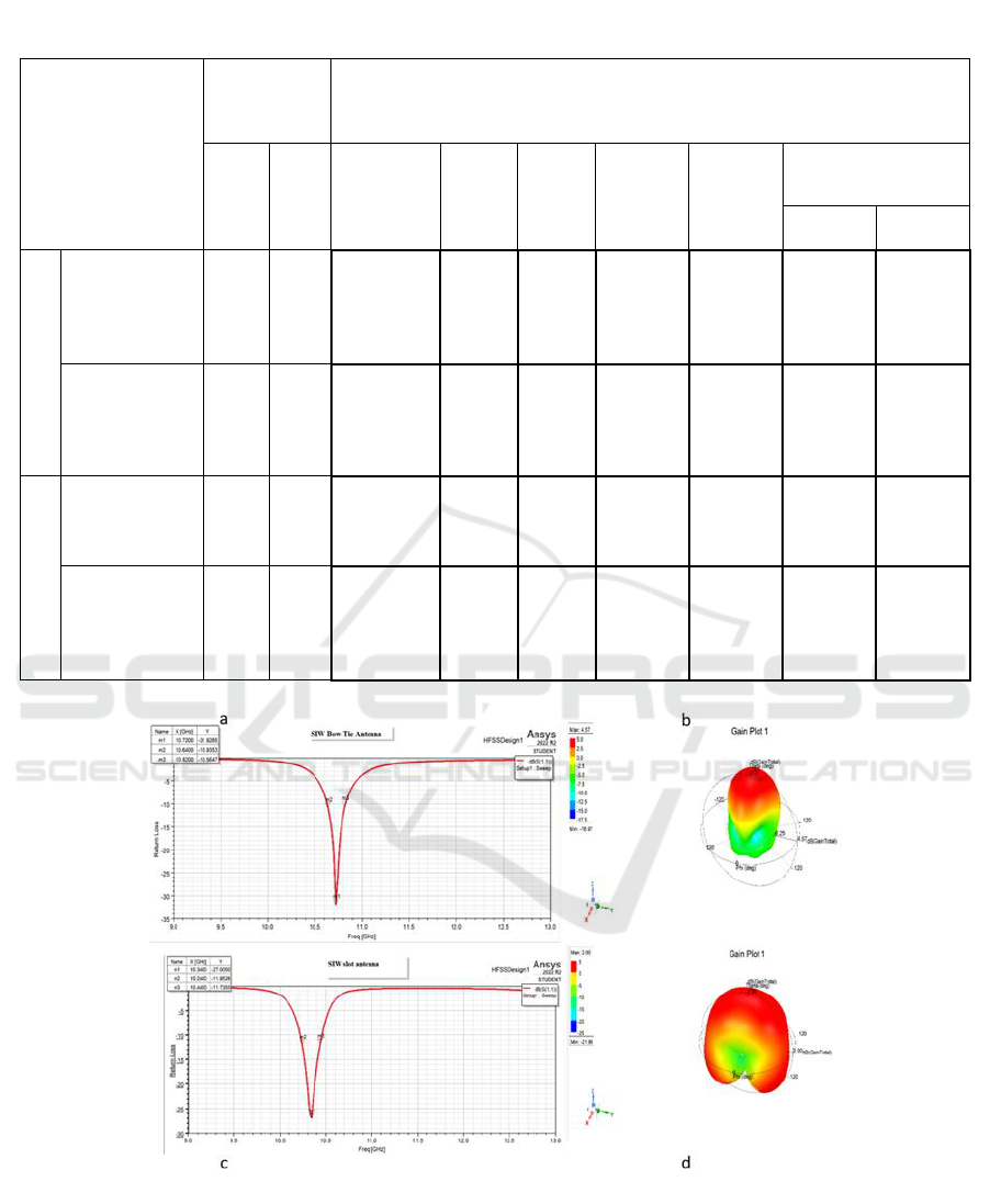
Table 5: Independent sample test between both groups (SIW Bow-Tie antenna and SIW Slot antenna). Analysis of groups in
detail the most significant in return loss p value is 0.036 and Gain p value is 0.000 (p<0.05).
Independent sample
test between both
groups (SIW Bow-Tie
antenna and SIW Slot
antenna)
Levene test of
equality for
variables
Equality of Mean’s T-test
F
Sig
t
df
Sig (2-
tailed)
Mean
difference
Std.
Error
difference
95% confidence
difference of interval
Lower
Upper
R
E
T
U
R
N
L
O
S
S
Equal variance
assumed
0.015
.049
.919
52
.036
2.01189
2.18992
-2.38250
6.40628
Equal variances
not assumed
.919
51.738
.036
2.01189
2.18992
-2.38303
6.40681
G
A
I
N
Equal variance
assumed
.000
1.155E+16
52
.000
2.57000
.00000
2.57000
2.57000
Equal variances
not assumed
.000
1.155E+16
26.000
.000
2.57000
.00000
2.57000
2.57000
Figure 2: SIW Bow Tie antenna (a) Return loss (b) Gain; (c) & (d) is the Return loss and Gain for the SIW slot antenna.
Simulating a Novel SIW Bow-Tie Antenna and Comparing Return Loss and Gain Performance with SIW Slot Antenna for X Band
Applications
17
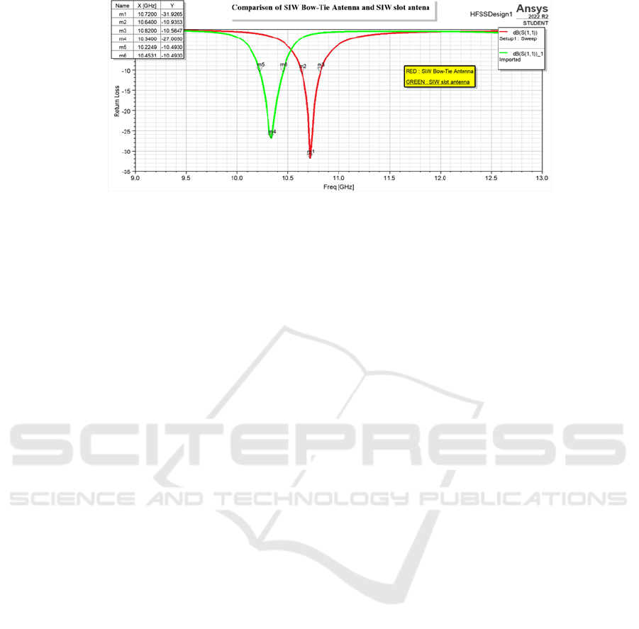
Figure 3: SIW Bow-Tie Antenna (-31.9265 dB) and SIW slot antenna (-27.0050 dB) comparison by its Return Loss
performance.
4 CONCLUSION
This research looks at and improves the Return Loss
and Gain of SIW Bow-Tie and SIW Slot antennas at
10 gigahertz. As an outcome, the suggestion was made
SIW Bow-Tie antenna (Return Loss: -31.9265, Gain:
4.57) outperforms the SIW Slot antenna (Return Loss:
-27.0050, Gain: 1.09). According to this, the SIW
Bow-Tie antenna is best usable for X band network
applications.
REFERENCES
Althuwayb, Ayman A. 2021. “MTM- and SIW-Inspired
Bowtie Antenna Loaded with AMC for 5G Mm-Wave
Applications.” International Journal of Antennas and
Propagation. https://doi.org/10.1155/2021/6658819.
Barik, Rusan K., Qingsha S. Cheng, Sounik K. K. Dash,
Nrusingha C. Pradhan, and Karthikeyan S.
Subramanian. 2020. “Design of a Compact Orthogonal
Fed Self‐diplexing Bowtie‐ring Slot Antenna Based on
Substrate Integrated Waveguide.” International Journal
of RF and Microwave Computer-Aided Engineering.
https://doi.org/10.1002/mmce.22422.
Chen, Xiaonan, Koji Iwano, Yasuhiko Sakai, and Yasumasa
Ito. 2022. “The Meandering Bend Features of Large-
Scale Structures and the Related Coherent Structures.”
International Journal of Heat and Fluid Flow.
https://doi.org/10.1016/j.ijheatfluidflow.2021.108915.
Dadgarpour, Abdolmehdi, Behnam Zarghooni, Bal S.
Virdee, and Tayeb A. Denidni. 2015. “Millimeter-Wave
High-Gain SIW End-Fire Bow-Tie Antenna.” IEEE
Transactions on Antennas and Propagation.
https://doi.org/10.1109/tap.2015.2406916.
Fernández-Bolaños, Montserrat, Catherine Dehollain, Pierre
Nicole, and Adrian M. Ionescu. 2010. “Tunable Band-
Stop Filter Based on Single RF MEMS Capacitive Shunt
Switch with Meander Arm Inductance.” Solid-State
Electronics. https://doi.org/10.1016/j.sse.2010.04.030.
Gan, Zheng, Zhi-Hong Tu, and Ze-Ming Xie. 2018.
“Pattern-Reconfigurable Unidirectional Dipole Antenna
Array Fed by SIW Coupler for Millimeter Wave
Application.” IEEE Access.
https://doi.org/10.1109/access.2018.2810194.
Kaur, Baljinder, and Lakhvinder Singh Solanki. 2012. “A
Brief Review on Bowtie Antenna.” In . Unpublished.
https://doi.org/10.13140/RG.2.1.2206.4805.
Kumar, Abhay, and Shweta Srivastava. 2021. “H-Plane
Bow-Tie SIW Horn Antenna for K Band Applications.”
2021 7th International Conference on Signal Processing
and Communication (ICSC).
https://doi.org/10.1109/icsc53193.2021.9673440.
Kumar, Arvind, and S. Raghavan. 2018. “Bandwidth
Enhancement of Substrate Integrated Waveguide
Cavity-Backed Bow-Tie-Complementary-Ring-Slot
Antenna Using a Shorted-Via.” Defence Science
Journal. https://doi.org/10.14429/dsj.68.11827.
Liu, Haiwen, Hao Jiang, Xuehui Guan, Jiuhuai Lei, and
Shen Li. 2013. “Single-Feed Slotted Bowtie Antenna for
Triband Applications.” IEEE Antennas and Wireless
Propagation Letters.
https://doi.org/10.1109/lawp.2013.2294751.
Liu, Li, Chengguang Zhang, Yu Liu, and Yujin Hua. 2018.
“A High Gain and Directivity Bow Tie Antenna Based
on Single-Negative Metamaterial.” Journal of
Microwaves, Optoelectronics and Electromagnetic
Applications. https://doi.org/10.1590/2179-
10742018v17i21116.
Madhav, B. T. P., Liquid Crystal Research Center, K L
University, Guntur, AP, India, Vgkm Pisipati, Habibulla
Khan, V. G. N. S. Prasad, K. Praveen Kumar, K. V. L.
Bhavani, et al. 2011. “Liquid Crystal Bow - Tie
Microstrip Antenna for Wireless Communication
Applications.” Journal of Engineering Science and
Technology Review 4 (2): 131–34.
Maruti, Ayyadevara Murali Dhara Vitala Naga, Ayyadevara
Murali Dhara Vitala Maruti, and Bhavan S. Naga
Kishore. 2022. “Dual-Band Siw Slot Array Filtering
Antenna For X And Ku Band Applications.” Progress
In Electromagnetics Research Letters.
https://doi.org/10.2528/pierl22020306.
AI4IoT 2023 - First International Conference on Artificial Intelligence for Internet of things (AI4IOT): Accelerating Innovation in Industry
and Consumer Electronics
18

Nandi, Sourav, and Akhilesh Mohan. 2016. “Bowtie Slotted
Dual-Band SIW Antenna.” Microwave and Optical
Technology Letters. https://doi.org/10.1002/mop.30035.
Nayak, Rashmiranjan, and Subrata Maiti. 2019. “A Review
of Bow-Tie Antennas for GPR Applications.” IETE
Technical Review.
https://doi.org/10.1080/02564602.2018.1492357.
Oliaei, Mahdi Norooz, and Mohammad Sadegh
Abrishamian. 2020. “Investigation of Corrugation and
Bow-Tie Loading on MMW SIW Antenna Using Higher
Order Modes.” 2020 28th Iranian Conference on
Electrical Engineering (ICEE).
https://doi.org/10.1109/icee50131.2020.9260848.
Robbins, W. P., and J. Bowers. 1978. “Comparison of the
Grating and Meander Line Transducers for
Magnetoelastic Surface Wave Excitation.” 1978
Ultrasonics Symposium.
https://doi.org/10.1109/ultsym.1978.197130.
Rosner, Bernard. 2015. Fundamentals of Biostatistics.
Cengage Learning.
Sayidmarie, Khalil Hassan, and Yasser A. Fadhel. 2013. “A
Planar Self-Complementary Bow-Tie Antenna For Uwb
Applications.” Progress In Electromagnetics Research
C. https://doi.org/10.2528/pierc12103109.
Tan, Li-Rong, Rui-Xin Wu, Cong-Yi Wang, and Yin Poo.
2014. “Ferrite-Loaded SIW Bowtie Slot Antenna With
Broadband Frequency Tunability.” IEEE Antennas and
Wireless Propagation Letters.
https://doi.org/10.1109/lawp.2014.2305431.
Varnoosfaderani, Mohammad Vatankhah, Junwei Lu, and
Boyuan Zhu. 2014. “Matching Slot Role in Bandwidth
Enhancement of SIW Cavity-Backed Slot Antenna.”
Proceedings of 2014 3rd Asia-Pacific Conference on
Antennas and Propagation.
https://doi.org/10.1109/apcap.2014.6992464.
Zabow, Gary, Stephen Dodd, and Alan Koretsky. 2021.
“The Misunderstood Meander: Redesigning MRI
Meander-Line Surface Coils to Reduce Noise, Increase
Uniformity, and Eliminate Image Artifacts.” Journal of
Magnetic Resonance 333 (December): 107100.
Simulating a Novel SIW Bow-Tie Antenna and Comparing Return Loss and Gain Performance with SIW Slot Antenna for X Band
Applications
19
