
Autonomous Driving Validation and Verification Using Digital Twins
Heiko Pikner
1
, Mohsen Malayjerdi
1
, Mauro Bellone
2
, Barıs¸ Cem Baykara
1
and Raivo Sell
1
1
Department of Mechanical and Industrial Engineering, Tallinn University of Technology, Tallinn, 19086 Estonia
2
FinEst Smart City Centre of Excellence, Tallinn University of Technology, Tallinn, 19086 Estonia
Keywords:
Autonomous Vehicles, Validation and Verification, Modeling and Simulation, Artificial Intelligence.
Abstract:
With the introduction of autonomous vehicles, there is an increasing requirement for reliable methods to
validate and verify artificial intelligence components that are part of safety-critical systems. Validation and
verification (V&V) in real-world physical environments is costly and unsafe. Thus, the focus is moving to-
wards using simulation environments to perform the bulk of the V&V task through virtualization. However,
the viability and usefulness of simulation is very dependent on its predictive value. This predictive value is a
function of the modeling capabilities of the simulator and the ability to replicate real-world environments. This
process is commonly known as building the digital twin. Digital twin construction is non-trivial because it in-
herently involves abstracting particular aspects from the multi-dimensional real world to build a virtual model
that can have useful predictive properties in the context of the model-of-computation of the simulator. With a
focus on the V&V task, this paper will review methodologies available today for the digital twinning process
and its connection to the validation and verification process with an assessment of strengths/weaknesses and
opportunities for future research. Furthermore, a case study involving our automated driving platforms will
be discussed to show the current capabilities of digital twins connected to their physical counterparts and their
operating environment.
1 INTRODUCTION
The Autonomous Vehicle (AV) industry aims to en-
sure system safety before mass deployment. Real-
world testing would take decades to accumulate over
tens of billion accident-free miles, which alone is not
a reliable safety indicator (Kalra and Paddock, 2016).
Among all testing methods, high-detail simulations
show better performance considering cost and time
(Thorn et al., 2018) (Matute-Peaspan et al., 2020).
Leveraging physics engines and digital twins of real-
world environments can significantly reduce testing
time and cost and try any upcoming potential feature
in varying operational design domains (ODDs), such
as weather conditions or traffic patterns. While AI-
based AV controllers are effective in real-world con-
ditions, they may disregard physical rules, resulting
in atypical decisions. As a result, the significance and
complexity of validation and verification V&V of au-
tonomous driving functionalities increases.
Verification and validation (V&V) is defined in the
ISO-IEC-IEEE 24765 (ISO-IEC-IEEE, 2017), as the
”process of determining whether the require-
ments for a system or component are complete
and correct, the products of each development
phase fulfill the requirements (...), and the fi-
nal system or component complies with speci-
fied requirements”.
It is clear from the definition in the standard that the
V&V process is aimed to verify specific predefined
requirements, typically described in a technical spec-
ification. However, the ISO also says that while the
process of verification ensures that the system has
been built right, the validation addresses the question
of whether the right system has been built for the spe-
cific task.
In autonomous driving, V&V of systems with
both deterministic and stochastic components poses
a challenge. Deterministic systems have predictable
behavior with known inputs and outputs, such as ve-
hicle hardware and electronics. In contrast, stochas-
tic processes, like object detection, have probabilistic
outputs. In consideration of these aspects, the V&V
process has to be carried out at the elementary level, in
which each component is validated individually, and
at an integration level, in which the V&V process is
carried out to all components working together.
From a V&V standpoint, validating a stochastic
204
Pikner, H., Malayjerdi, M., Bellone, M., Baykara, B. and Sell, R.
Autonomous Driving Validation and Verification Using Digital Twins.
DOI: 10.5220/0012546400003702
Paper published under CC license (CC BY-NC-ND 4.0)
In Proceedings of the 10th International Conference on Vehicle Technology and Intelligent Transport Systems (VEHITS 2024), pages 204-211
ISBN: 978-989-758-703-0; ISSN: 2184-495X
Proceedings Copyright © 2024 by SCITEPRESS – Science and Technology Publications, Lda.

process means verifying its entire probability distri-
bution. Take dice rolling as an example; you would
need to roll the dice thousands of times to ensure each
face appears equally. However, for complex systems
like AVs, there are countless scenarios, making it im-
practical to physically test all outcomes. This is where
digital twinning technology shines, allowing the com-
putation of thousands of scenarios to predict system
behavior. The precision of the digital twin directly
impacts V&V fidelity. This paper explores recent dig-
ital twinning techniques in AVs and their distinctions
from our custom platform.
2 RELATED WORK
Any industrial product, including AVs, starts its em-
bryonic life from a Computer Aided Design (CAD)
model with the goal of representing the idea, and
continues to the Computer Aided Engineering (CAE)
process that aims to optimize and test initial function-
alities. Such a product eventually goes to the produc-
tion stage in which Computer Aided Manufacturing
(CAM) comes into the game, optimizing the man-
ufacturing process. The industrial world very often
confuses such processes as the digital twining process
that, instead, has a fundamental difference: it repre-
sents a product as built, operating in the real world,
and receiving data from it. These three characteris-
tics are intrinsic and fundamental to defining a digital
twin resembling a real product in its operational envi-
ronment. CAD models represent a model as it could
be, whereas digital twins represent the model as it is.
Literature in the field often refers to digital twins
as an asset that improves products along their life cy-
cle (L
¨
ocklin et al., 2020). From this point of view, it
is clear that CAD-CAM models and digital twins are
very different objects, but CAD models are elements
of digital twins.
The definition of digital twins was introduced by
NASA 2012 (Shafto et al., 2012) with the necessity
of modeling as accurately as possible flight condi-
tions for astronauts in space or other environments,
then shifted to other domains, including industrial en-
gineering and robotics (Negri et al., 2017). NASA
defines a digital twin (Shafto et al., 2012) as
”an integrated multiphysics, multiscale sim-
ulation of a vehicle or system that uses the
best available physical models, sensor up-
dates, fleet history, etc., to mirror the life of
its corresponding flying twin”.
While the initial NASA’s definition includes all the
main components of digital twins, it lacks generality
and new functionalities. For this reason, the definition
has been updated and generalized, referring to a dig-
ital replica of a physical system able to mirror all its
static and dynamic characteristics (Talkhestani et al.,
2018). However, it is really when digital twins start
receiving data from their physical counterparts that
becomes powerful, exploiting computational capabil-
ities to predict failures and drive update strategies.
One can also see the digital twin as the feedback loop
of a physical system, receiving data and thus correct-
ing possible unexpected outcomes. In this approach,
also AVs and their testing environments can be con-
nected to their digital twins in the simulated space.
Nowadays, a commercial car has an expected lifespan
of about 10-15 years. These vehicles, autonomous or
not, already have many software functionalities that
could be improved and updated over time, keeping
the same hardware components. Digital twinning al-
lows manufacturers to continuously simulate each ve-
hicle’s behavior and receive data from their physical
counterparts to verify and validate products and com-
ponents, detecting possible faults in advance and re-
leasing a fix via software update.
AV simulations, for example, in CARLA (Doso-
vitskiy et al., 2017), and Autoware (Kato et al., 2018),
mainly use the concept of the digital twin to validate
and verify the safety and performance of those vehi-
cles. Autoware is an open-source software project for
autonomous driving, while CARLA focuses on game-
engine based simulation and providing assets to build
environments (urban details, road users, etc.).
AWSIM (Autoware Foundation, 2022) and
CARLA are simulators that were built on top of these
game engines with a specific focus on automated
driving. On the other side of the ocean, Baidu is
also driving the sector with the Apollo
1
open-source
simulation and verification platform focusing on au-
tonomous driving with several iterations of develop-
ment. A testing case of this framework can be found
in (Li et al., 2023).
An example of V&V platform, the PolyVerif
2
framework is very well detailed in (Razdan et al.,
2023) and (Alnaser et al., 2019). Since the verifica-
tion of physical objects is costly, not scalable, and has
obvious safety concerns, this platform has been de-
veloped based on simulation methods. With any form
of simulation, one must directly address the nature of
model abstraction, and this is typically aligned with
the operational abstraction of the Device Under Test
(DUT), the AV stack in our case. Overlaid on the sim-
ulation framework is the design-of-experiment (DOE)
1
Apollo, 2022: https://github.com/ApolloAuto/apollo
2
The Source code repository of polyVerif
is available online and maintained at
https://github.com/MaheshM99/PolyVerif
Autonomous Driving Validation and Verification Using Digital Twins
205

Operating
environment
data collection
Post
processing
and filtering
Vehicle
design model
Scenario
description
Interface Simulator
Autoware
stack
Validation report
Digital twin creation
Sensory data
Vehicle ctrl
signals
V&V suite
Figure 1: V&V suite workflow with digital twin, including
environment and vehicles, as input to the V&V suite to pro-
vide a validation report.
unit consisting of a variety of scenarios (environment,
dynamic actors) and some definition of correctness
(pass/fail). The general workflow of a V&V platform
is shown in Fig. 1. The framework defines an inter-
face where the scenario definitions can be fed into the
simulator. The digital twin, including a vehicle under
the test and its operating environment, is a direct in-
put to the simulator as an external loadable. It defines
the environment domain and its properties, such as
buildings, vegetation, road definitions, etc. The simu-
lator runs alongside the Autoware stack to aggregate
the scenario definitions within that digital twin envi-
ronment, and based on the outcome, it produces vali-
dation reports. The scenario description includes the
specific use case of the vehicle in the environment to
be validated.
3 DOE VALIDATION FLOWS
For a serious V&V task, one must build a Design
of Experiment (DOE) infrastructure that is program-
matic in nature. Key elements of the DOE flow
mimic the process for any large, sophisticated soft-
ware project with elements. In summary, five concrete
methods are provided to validate various parts of the
AV stack. These flows provide researchers with an
initial understanding of the framework and encourage
them to build derivatives that extend the paradigm in
interesting directions.
In terms of modeling abstraction, the Autoware
AV stack (Kato et al., 2018) (or any AV stack) is op-
erating in a conventional Newtonian physics universe.
To be useful, any simulation environment must model
key concepts such as momentum, graphic process-
ing, sound dynamics, and more. These concepts can
be modeled at various levels of fidelity with a trade-
off between accuracy and simulation performance
(Malayjerdi et al., 2023b). At a component level, the
internal useful abstractions of the major pieces of the
Autoware AV stack are detection, control, localiza-
tion, mission planning, and low-level control. Each
Objects available
in the ground truth
Objects detected
by the AV stack
NPC
NPC
Figure 2: Detection validation example. The Ground truth
of the detectable vehicle is indicated using green boxes
while the detection is marked using red boxes.
of these modules is detailed below.
Detection Validation. The V&V framework con-
structs detection validation by introducing stubs in the
simulator to capture errors between the ground truth
data and the Autoware stack detection log. This data
logging is done on a per-frame basis, and the com-
plete dataset is recorded in separate files for each of
the test cases executed. Further, the framework auto-
matically generates a figure of merit for the AV detec-
tion module performance. While generating results
for object detection, below details can be considered
(but not limited to):
• Frame-by-frame validation
• Report on objects detected by AV stack success
and failure per object per frame.
• Distance-based accuracy report generation, as
lesser distant objects are important for control.
E.g. Detection success/failure rate in the range
0-10 meters, 10-20 meters, etc.
Figure 2 explains about object comparison. Green
boxes are shown for objects captured by ground truth,
while Red boxes are shown for objects detected by
AV stack. Threshold-based rules are designed to com-
pare the objects. It is expected to provide specific in-
dicators of detectable vehicles in different ranges for
safety and danger areas.
Control Validation. In Control Validation, the
framework checks the impact of detection on the
AV stacks control mechanism. This validation en-
ables safety testing of controls like automatic braking
mechanisms by computing response time and braking
distance parameters. The objects ground truth is cap-
tured from the simulator while perception results are
captured from the AV stack with CANBUS data, to
know the control instructions from the AV stack to the
CARLA simulator. V&V algorithms are written to
compare data and validate the AV stacks algorithms’
efficiency and accuracy. Computed Information is as
below:
• Time-To-Collision T TC
i
=
∆x
v
rel
VEHITS 2024 - 10th International Conference on Vehicle Technology and Intelligent Transport Systems
206
NPC
NPC
Ego
Buffer area
Collision area
v
x
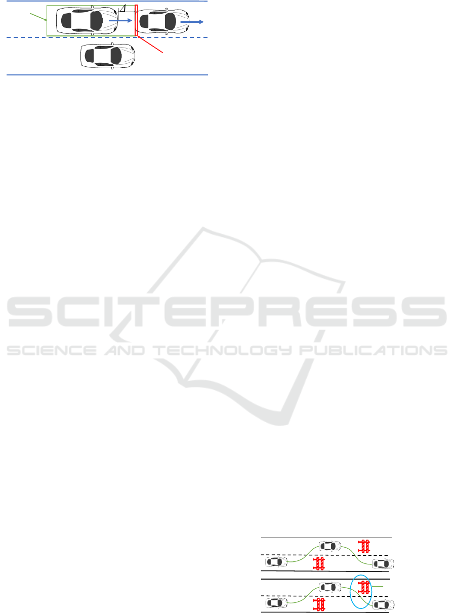
Figure 3: Time to Collisions Calculations and Collision
Scenario.
• Simulator Response time on obstacle detection
• AV-stack Response time on obstacle detection
• Delay in response due to perception/detection
Figure 3 shows this concept in further detail,
showing an ego-vehicle driving on the lane with other
vehicles (NPCs), the time to collision is calculated us-
ing the simplest possible kinematic model using the
relative speed between two vehicles.
Sufficient response time for AVs helps to return
to a safer position without an imminent collision and
by engaging the required braking force. Delay in re-
sponse may cause collision and failure of AV sys-
tems.Computed parameters help in knowing the role
of perception, their role in control initiation, and sys-
tems success/failure.
Current implementation rules consider highways
and front/rear collisions from NPCs. Also, future
plans are to consider all types of road infrastruc-
tures/junctions and static/pedestrian collisions from
all directions.
Localization Validation. Vehicle localization failure
leads to collision or accidents. Every AV stack has
many inbuilt algorithms to ensure the accurate posi-
tioning of the vehicle. These algorithms use multiple
sensors e.g. GPS/IMU for absolute position compu-
tation and other sensors like LIDAR/Camera/RADAR
for relative position computation.
Under this validation, the V&V framework vali-
dates AV stacks localization algorithms and tests the
capabilities of these algorithms in the case of GPS sig-
nal loss for a short period of time. This validation also
helps in testing the localization mechanism by intro-
ducing different levels of noise into GPS/IMU sen-
sor readings. The GPS and IMU noise can be mod-
eled as per user requirements, and modified data can
be published from the simulator to the AV stack to
verify the behavior of the AV. The current validation
method performs one-to-one mapping from the ex-
pected location vs. the actual location. Per frame,
the vehicle position deviation value is computed and
captured in the validation report. Later parameters
like min/max/mean deviations are calculated from the
same report.
In the validation procedure is also possible to
modify the simulator to embed a mechanism to add
noise in GPS/IMU data and provided the APIs to the
end user. Through Python APIs, parameters can be
passed to the simulator. The API internally models
the noise and introduces the modified data in the sim-
ulation.
Mission Planning Validation. Each AV mission re-
quires the capture of information from every possi-
ble sensor and the use of algorithms to move the ve-
hicle safely to its destination based on that informa-
tion. The success of the planned mission depends
on the accuracy of these algorithms and the detec-
tion/perception of captured data by the sensors. Mis-
sion planning validation considers the start and goal
position for the AV to navigate. Once these are set the
AV generates a global trajectory based on the current
location and the given destination. As shown in Fig. 4,
the proposed platform validates that the trajectory is
safely followed till the goal position. The validation
report provides information on the trajectory follow-
ing errors, collisions that have occurred, and whether
the AV has reached its destination.
Low-Level Control Validation. Low-level control
systems involve electronic control modules (ECUs),
data networks, and mechanical actuators. In modern
vehicles, there may be over 80 ECUs in some cases,
therefore, validating a low-level control system re-
quires substantial labor and effort.
Classic solutions involve recording vehicle data
bus traffic for post-processing or playback. Often,
data packages in networks include checksum and
other security elements. Manipulating pre-stored logs
and altering specific signals is only possible by recal-
culating the checksum for each modified data pack-
age. These packages also contain counters, so simply
deleting them would result in corrupted counter val-
ues.
Building a network of physical controllers can ad-
dress the package generation challenge, but creating
and validating such a network is labor-intensive. Ad-
ditionally, testing vehicle subsystems in this simpli-
fied manner may yield undesirable results.
The next objective is to create a simulated low-
level control system model inside a digital twin.
One such tool is MATLAB and Simulink software.
Simulink software allows the generation of a sim-
Safety validation
required for risky paths
Obstacle
Figure 4: Trajectory validation example.
Autonomous Driving Validation and Verification Using Digital Twins
207

ulated low-level architecture for vehicles, including
ECUs, and data buses as shown in Fig. 5. The au-
tonomous software in ROS can generate navigation
signals based on the virtual sensor data provided by
the simulator. All navigation signals pass through the
simulated low-level control system model and enter as
actuation commands into the simulator. So, for exam-
ple, the consequence of turning off the steering sys-
tem model would be that the control signal from the
ROS computer would no longer turn the simulated ve-
hicle wheels.
The gateway module facilitates the connection be-
tween physical and simulated data flow. This setup
enables testing stand-alone ECUs or vehicle subsys-
tems in a hardware-in-loop (HIL) environment when
a vehicle self-drives inside a simulation and simulta-
neously generates all the traffic on the data network.
Such a test system facilitates easy and rapid val-
idation for developing control modules and simulat-
ing system operation. Different designed situations
and disturbances allow for performing various tests. It
also provides testing scenarios that would be too haz-
ardous to conduct in real traffic scenarios. Stability
and durability can be evaluated by running tests for an
extended period. Furthermore, the parameters of an
actual vehicle can be compared against the model, and
any discrepancies between the vehicle and the digital
twin in response to the same input might indicate a
possible fault.
4 CASE STUDY: TESTING AN
Av-shuttle
To decrease the entry barrier for researcher engage-
ment, we provide a fully characterized AV-focused
case study as a part of the V&V platform. We pro-
vide test cases by implementing an autonomous shut-
tle, iseAuto, in the simulated and real-world environ-
ment with the interesting premise that improvements
Figure 5: Low-level control system HIL simulation exper-
imental structure. All of the vehicle’s controllers are sim-
ulated, and while the simulation is running, traffic is gen-
erated on a simulated data network that can be used to test
and develop physical controllers.
in Autoware or V&V can be tested in cooperation
with other research groups. The iseAuto is an au-
tonomous shuttle of Tallinn University of Technol-
ogys (TalTech) AV research group operating on the
campus for experimental and study purposes. The AV
shuttle and its related operating environment are con-
nected to its digital twin, enabling running all devel-
opments first in a simulation. The simulation environ-
ments, interfaces, and concepts are described in detail
in (Sell et al., 2022), and (Malayjerdi et al., 2023a).
4.1 Digital Twin of the iseAuto Shuttle
The initial design model of the iseAuto shuttle was
used and constantly updated to deploy its digital twin,
which is used as a DUT in any desired environment
designed for testing and validation. The DUT digi-
tal twin contains the same sensor configuration as the
real device and the 3D graphical model. The vir-
tual environment also represents similar features to
the actual test area; features such as urban details
and vegetation are simulated within the environment.
LGSVL (Rong et al., 2020) is deployed in the pro-
posed platform as a vehicle simulator powered by the
Unity game engine. This enables the creation of any
desired virtual environment and the target vehicle to
provide more flexibility and compliance in perform-
ing various tests. The simulator also benefits from a
Python API toolkit to create different test scenarios
based on pre-built features. It is also possible to im-
port scenarios from a different platform (Malayjerdi
et al., 2023a), e.g. SUMO (Behrisch et al., 2011).
To create a more complex test plan, multiple
events can be included in one scenario. After run-
ning a simulation, the simulator provides virtual sen-
sor inputs to the control algorithms provided by Au-
toware.ai. The raw data is received by the percep-
tion algorithms and then processed by various units.
Finally, the software decides on the required actua-
tion command and sends it back to the simulator en-
vironment. This communication is handled through
a ROS bridge. Based on each study objective, vari-
ous safety and performance KPIs are defined and the
corresponding data is recorded during the runs. We
then analyze and observe these criteria to find the vul-
nerabilities and corner cases where the DUT violated
the metrics (Malayjerdi et al., 2023a; Roberts et al.,
2023).
The data collection used in iseAuto is an end-
to-end general-purpose AV data collection frame-
work featuring algorithms for sensor calibration, in-
formation fusion, and data space to collect hours of
robotics-related application that can generate data-
driven models (Gu et al., 2023). The novelty of
VEHITS 2024 - 10th International Conference on Vehicle Technology and Intelligent Transport Systems
208
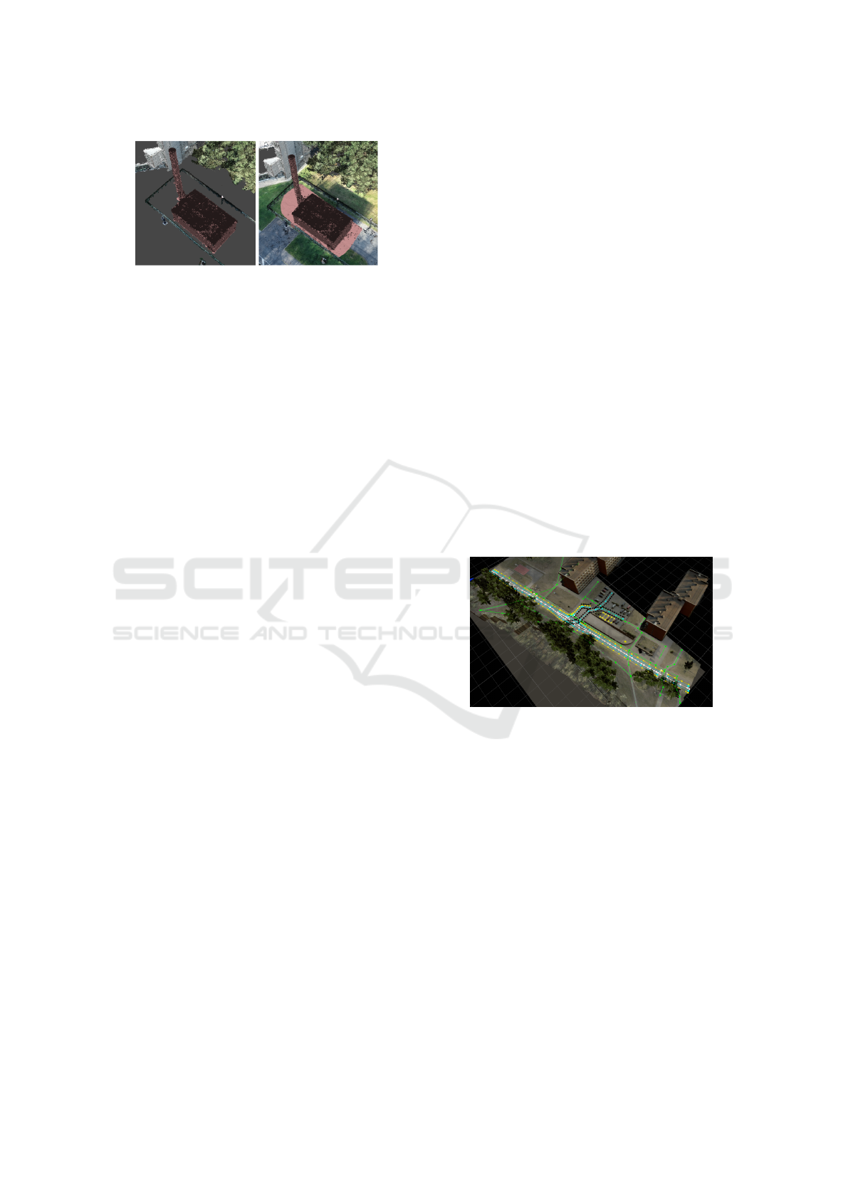
Figure 6: Comparison between point selection in segmented
point-cloud and non-segmented point-cloud.
this dataset collection framework is that it covers
the aspects from sensor hardware to the developed
dataset that can be easily accessed and used for other
AD-related research. The framework has backend
data processing algorithms to fuse the camera, Li-
DAR, and radar sensing modalities together. De-
tailed hardware specifications and the procedures to
build the data acquisition and processing systems can
be found in (Gu et al., 2023). Data collection and
update are crucial parts of the digital twin creation
process, which involves several resource-demanding
steps. However, it is worth mentioning that the digi-
tal map of an area can be reused in the digital twining
process of several AVs or other types of robotic units
as well.
The digital twin of the shuttle without its opera-
tional environment remains just a CAD model. To ac-
curately represent the real environment in which the
AV operates in a digital world (i.e., the workspace in
which the AVs operate), aerial images of the environ-
ment must be collected. This can be done in various
ways and with various sensors (LIDAR, RGB Cam-
era, etc.).
In the case study proposed here, a drone with
an RGB camera has been used in a grid flight path
at a constant altitude to take sequential images of
the environment. These images have been collected
from three different angles to ensure the best possi-
ble coverage of the environments details. The im-
ages are georeferenced with a coordinate stamp by
the drone acquisition system itself, the georeferenc-
ing process was supported by an RTK base station
and ground markers to increase georeferencing ac-
curacy. This makes it possible to photogrammetri-
cally process them to obtain a point cloud of the en-
vironment. A small misalignment of the georefer-
enced images or unexpected glares on the camera’s
lens could degrade the point cloud’s quality. Once the
data has been collected, it goes through a photogram-
metric alignment, point-cloud creation, and outlier re-
moval process. This part is completely handled us-
ing commercially available software. This step makes
it significantly easier to select and classify the point
cloud and to clean it up from unwanted noise (see Fig.
6). The previously generated point clouds are then
re-imported into Agisoft Metashape for classification
and cleanup. It is also worth mentioning that after
these processes are completed, one could easily gen-
erate buildings from this data directly in Metashape in
any desired format.
4.2 TalTech iseAuto V&V
All of the steps required for the V&V process includ-
ing the creation of the digital twin, scenario genera-
tion, and simulation are integrated into the simulation
platform. As a primary step, an openDRIVE network
map (xodr) of the target environment is needed. Fig-
ure 7 shows an example of a xodr map over the operat-
ing 3D virtual environment. In the next step, this map
is used by the Scenic (Fremont et al., 2022) to gener-
ate distributed test cases all over the area. Scenic uti-
lizes M-SDL, a human-readable, high-level scenario
definition language, to describe scenarios. Several
generated scenarios for a car parked in front of the
AV are shown in Fig. 8. Scenic assists in the distri-
bution of the target validation scenario over the entire
operational area.
Figure 7: OpenDRIVE map over the 3D environment.
The generated scenarios are then simulated in-
side a high-fidelity simulator, which in this case is
LGSVL. Fig. 9 displays 4 different passing scenarios
generated by scenic and simulated in the simulator 3D
environment.
5 DISCUSSION AND
CONCLUSIONS
V&V of AV systems is a very difficult problem and
there is a need to build research frameworks that can
accelerate the state-of-art. However, a current limita-
tion is that the current examples take into account AI
components only in the detection module. Many re-
search questions arise from the use of AI, for instance,
AI fundamentally builds a model from data with ef-
Autonomous Driving Validation and Verification Using Digital Twins
209
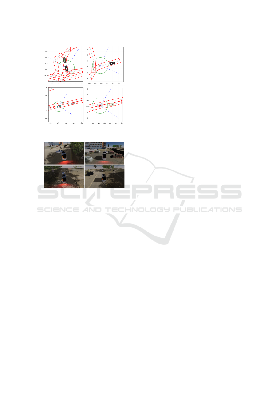
Figure 8: Scenic generates different scenarios over the xodr
imported map.
Figure 9: Scenarios generated by the scenic inside the
LGSVL.
fectively an opaque lookup function for inference.
This means data in the ”algorithm” does not have
a deterministic outcome in the operational domain
as even a slight variation might generate unexpected
outcomes. How can one validate the data projected
through training for conformance to the appropriate
Operational Design Domain (ODD) state space and
its behavioral transformations? For AI, how does one
capture ”expectation” functions to determine correct-
ness when there is a lack of a system design modeling
methodology? Many AI applications use AI to ”dis-
cover” the highest level system transformation. The
answers to the above questions lead to the computa-
tional convergence questions.
An intuition would be to build a formalization
of ODD state spaces and create a method for ex-
amining the data sets under that constraint. In the
AI area, the only well-established method is cross-
validation, involving the swap between several train-
validation sub-datasets to confirm the model perfor-
mances within a specific variance threshold. While
cross-validation provides a measure of the knowledge
abstraction capabilities of AI modules, it does not en-
sure that the final model is built in compliance with
any well-established standard in the area.
Research Problem 1. For AI train-
ing/inference, is there a more robust theory of
convergence?
Current convergence criteria are based on loss-
functions minimization and regularization methods.
This means that the training stops when the minimiza-
tion of the loss function does not improve anymore
over time, and the best model is chosen over the best
loss function value or using any early stopping crite-
ria that measure the accuracy of the validation data.
These criteria seem weak from a general knowledge
abstraction point of view as validation and training
datasets might be slightly different and the mathemat-
ical assurance of convergence exists only asymptoti-
cally (for the dataset size that goes to infinity).
Research Problem 2. For AI V&V, is there
any theory of convergence?
The questions might seem similar at first glance,
but they consider two different aspects, the training
procedure of the model, and the validation procedure
as the model is integrated into a product (e.g. a vehi-
cle). Typically, V&V is exponential in terms of sce-
narios to consider, it is possible to use a number of
techniques that employ abstraction to manage com-
plexity but most of these techniques do not work with
AI inference or work only on a limited subset of cases.
For AV in particular, further open research ques-
tions include:
• Newtonian Physics. Autonomy exists in the
physical world. The physical world is governed
by physics (Maxwell, Newton). This should be
a great aid in helping set a governing framework
for validation. How might one use the proper-
ties from physics to build a validation governor
around AI-based autonomy systems?
• Component Validation. Each of the major steps
in the AV pipeline (Detection, Perception, Loca-
tion Services, Path Planning, etc) has its chal-
lenges. Can one build robust component-level val-
idation for each of these?
• Abstraction. Complex problems are solved by
the use of abstraction. Is it possible to leverage
component validation such that deeper scenario
validation can be done at a higher level of abstrac-
tion? If so, what are the abstractions of concern?
The field of AV and AV V&V is rich with open
research problems. However, it is very difficult to
make progress without a very large level of infras-
tructure. A cooperative open-source model is critical
for progress, and the proposed platform is designed
to help researchers quickly experiment with state-of-
the-art ideas in this direction.
VEHITS 2024 - 10th International Conference on Vehicle Technology and Intelligent Transport Systems
210

In conclusion, this paper underscores the pivotal
role of digital twins in addressing validation and veri-
fication challenges associated with the principal com-
ponents in AVs. Through a comprehensive review of
current methodologies, this study elucidates the nu-
anced connection between the digital twining process
and the imperative task of ensuring safety-critical sys-
tems reliability. The assessment of strengths, weak-
nesses, and opportunities for future research reveals
the intricacies involved in constructing digital twins
with high predictive value.
ACKNOWLEDGEMENTS
This work has been supported by the European Union
through the H2020 project Finest Twins (grant No.
856602).
REFERENCES
Alnaser, A. J., Akbas, M. I., Sargolzaei, A., and Razdan, R.
(2019). Autonomous vehicles scenario testing frame-
work and model of computation. SAE International
Journal of Connected and Automated Vehicles, 2(4).
Autoware Foundation (2022). TIER IV AWSIM. https:
//github.com/tier4/AWSIM.
Behrisch, M., Bieker, L., Erdmann, J., and Krajzewicz,
D. (2011). Sumo–simulation of urban mobility: an
overview. In Proceedings of SIMUL 2011, The Third
International Conference on Advances in System Sim-
ulation. ThinkMind.
Dosovitskiy, A., Ros, G., Codevilla, F., Lopez, A., and
Koltun, V. (2017). Carla: An open urban driving sim-
ulator. In Conference on robot learning, pages 1–16.
PMLR.
Fremont, D. J., Kim, E., Dreossi, T., Ghosh, S., Yue,
X., Sangiovanni-Vincentelli, A. L., and Seshia, S. A.
(2022). Scenic: A language for scenario specification
and data generation. Machine Learning, pages 1–45.
Gu, J., Lind, A., Chhetri, T. R., Bellone, M., and Sell, R.
(2023). End-to-end multimodal sensor dataset collec-
tion framework for autonomous vehicles.
ISO-IEC-IEEE (2017). Systems and software engineering
-vocabulary. IEEE.
Kalra, N. and Paddock, S. M. (2016). Driving to safety:
How many miles of driving would it take to demon-
strate autonomous vehicle reliability? Transportation
Research Part A: Policy and Practice, 94:182–193.
Kato, S., Tokunaga, S., Maruyama, Y., Maeda, S.,
Hirabayashi, M., Kitsukawa, Y., Monrroy, A., Ando,
T., Fujii, Y., and Azumi, T. (2018). Autoware on
board: Enabling autonomous vehicles with embedded
systems. In 2018 ACM/IEEE 9th International Con-
ference on Cyber-Physical Systems (ICCPS), pages
287–296. IEEE.
Li, H., Makkapati, V. P., Wan, L., Tomasch, E., Hoschopf,
H., and Eichberger, A. (2023). Validation of auto-
mated driving function based on the apollo platform:
A milestone for simulation with vehicle-in-the-loop
testbed. Vehicles, 5(2):718–731.
L
¨
ocklin, A., M
¨
uller, M., Jung, T., Jazdi, N., White, D., and
Weyrich, M. (2020). Digital twin for verification and
validation of industrial automation systems–a survey.
In 2020 25th IEEE international conference on emerg-
ing technologies and factory automation (ETFA), vol-
ume 1, pages 851–858. IEEE.
Malayjerdi, M., Goss, Q. A., Akbas¸, M.
˙
I., Sell, R., and
Bellone, M. (2023a). A two-layered approach for the
validation of an operational autonomous shuttle. IEEE
Access.
Malayjerdi, M., Kaljavesi, G., Diermeyer, F., and Sell, R.
(2023b). Scenario-based validation for autonomous
vehicles with different fidelity levels. In 2023 IEEE
26th International Conference on Intelligent Trans-
portation Systems (ITSC), pages 1–6.
Matute-Peaspan, J. A., Zubizarreta-Pico, A., and Diaz-
Briceno, S. E. (2020). A vehicle simulation model and
automated driving features validation for low-speed
high automation applications. IEEE Transactions
on Intelligent Transportation Systems, 22(12):7772–
7781.
Negri, E., Fumagalli, L., and Macchi, M. (2017). A re-
view of the roles of digital twin in cps-based produc-
tion systems. Procedia manufacturing, 11:939–948.
Razdan, R., Akba, M. ., Sell, R., Bellone, M., Menase,
M., and Malayjerdi, M. (2023). Polyverif: An open-
source environment for autonomous vehicle validation
and verification research acceleration. IEEE Access,
11:28343–28354.
Roberts, A., Malayjerdi, M., Bellone, M., Maennel, O.,
and Malayjerdi, E. (2023). Analysing adversarial
threats to rule-based local-planning algorithms for au-
tonomous driving. Network and Distributed System
Security (NDSS) Symposium.
Rong, G., Shin, B. H., Tabatabaee, H., Lu, Q., Lemke,
S., Mo
ˇ
zeiko, M., Boise, E., Uhm, G., Gerow, M.,
Mehta, S., et al. (2020). LGSVL simulator: A high
fidelity simulator for autonomous driving. In 23rd
International conference on intelligent transportation
systems (ITSC), pages 1–6. IEEE.
Sell, R., Malayjerdi, E., Malayjerdi, M., and Baykara, B. C.
(2022). Safety toolkit for automated vehicle shuttle-
practical implementation of digital twin. In 2022
International Conference on Connected Vehicle and
Expo (ICCVE), pages 1–6. IEEE.
Shafto, M., Conroy, M., Doyle, R., Glaessgen, E., Kemp,
C., LeMoigne, J., and Wang, L. (2012). Model-
ing, simulation, information technology & processing
roadmap. National Aeronautics and Space Adminis-
tration, 32(2012):1–38.
Talkhestani, B. A., Jazdi, N., Schl
¨
ogl, W., and Weyrich,
M. (2018). A concept in synchronization of virtual
production system with real factory based on anchor-
point method. Procedia Cirp, 67:13–17.
Thorn, E., Kimmel, S. C., Chaka, M., Hamilton, B. A., et al.
(2018). A framework for automated driving system
testable cases and scenarios. Technical report, United
States. Department of Transportation. National High-
way Traffic Safety .
Autonomous Driving Validation and Verification Using Digital Twins
211
