
Model-Based Auto-Commissioning of Building Control Systems
Philipp Zech
1 a
, Emanuele Goldin
1
, Sascha Hammes
2 b
, David-Geisler Moroder
2 c
,
Rainer Pfluger
2
and Ruth Breu
1
1
Department of Computer Science, University of Innsbruck, Technikerstrasse 21a, Innsbruck, Austria
2
Unit of Energy Efficient Building, University of Innsbruck, Technikerstrasse 13, Innsbruck, Austria
fl
Keywords:
Model-Based Development, Building Information Modeling, Auto-commissioning, Digital Twins.
Abstract:
Digital twins are valuable instruments for model-based design, commissioning, and operation, with signifi-
cant applicability potential in the construction industry. Whereas with Building Information Modeling (BIM)
a standard for the representation of building models has been established, these models lack (i) modeling sup-
port for building control systems, and (ii) tool-based automation support for model-based auto-commissioning
of building automation systems, an instrumental factor in putting a digital twin in operation. In this paper,
we present a domain-specific language (DSL), its modeling methodology, and tool support to augment and
condition BIM models for auto-commissioning. Preliminary results from an early prototype evaluation using
the Technology Acceptance Model demonstrate the feasibility of our proposal in contributing to the improve-
ment of building operations by facilitating auto-commissioning of building control systems and subsequent
commissioning of digital twins.
1 INTRODUCTION
Digital twins (DT) represent virtual replicas of cyber-
physical systems (CPS) comprising (Grieves and
Vickers, 2017)
• a virtual entity, i.e., the assemblage of models de-
scribing the CPS’ manifestation,
• a physical entity, i.e., the running instance of the
‚CPS, and
• interchanged data and connection between the vir-
tual and physical instance, respectively,
and represent valuable instruments the for model-
based design and operation of CPSs. DTs provide
increased planning and operational efficiency, de-
creased interruption, improved product quality, opti-
mized resource utilization, and enhanced innovation
through simulation and analysis of real-time data (Se-
meraro et al., 2021). Due to their capacity to auto-
mate building operations, the architecture, engineer-
ing, construction, and operation (AECO) domain is
increasingly interested in adopting DTs to improve
project design, planning, construction management,
a
https://orcid.org/0000-0002-4952-4337
b
https://orcid.org/0000-0001-5821-5053
c
https://orcid.org/0009-0002-3641-6182
resulting in improved collaboration, cost savings,
schedule optimization, and better asset performance
throughout the entire lifecycle of buildings (Ozturk,
2021). A DT for automating building operations
leverages a virtual representation of a building that in-
corporates building control system (BCS) data to pro-
duce an accurate digital model. It enables building
planners and operators to design, simulate and opti-
mize BCS in the planning phase and during operation
by auto-commissioning the BCS from the DT during
initial building operation and later re-commissioning.
Specifically, the integration of DTs, Building Infor-
mation Modeling (BIM), and building automation
enables stakeholders to create a model-based, dy-
namic, high-fidelity digital representation of a build-
ing for building operations and Computer-Aided Fa-
cility Management (CAFM). BIM and BCS are two
distinct, yet interdependent technologies and method-
ologies that perform complementary roles in the de-
sign, construction, and operation of buildings, viz.,
during the
• design phase, BIM can provide valuable and de-
tailed information for planning and simulation so
that calculations, system dimensioning and spec-
ifications can be substantiated and optimized. In-
formation that subsequently informs design deci-
sions for the BCS;
Zech, P., Goldin, E., Hammes, S., Moroder, D., Pfluger, R. and Breu, R.
Model-Based Auto-Commissioning of Building Control Systems.
DOI: 10.5220/0012554000003690
Paper published under CC license (CC BY-NC-ND 4.0)
In Proceedings of the 26th International Conference on Enterprise Information Systems (ICEIS 2024) - Volume 2, pages 121-128
ISBN: 978-989-758-692-7; ISSN: 2184-4992
Proceedings Copyright © 2024 by SCITEPRESS – Science and Technology Publications, Lda.
121

• construction phase, coordination between BIM
and BCS trades ensures that BCS components are
installed and configured per design specifications;
• operation phase, BCS are auto-commissioned
from the BIM model and are responsible for
the surveillance, control, and optimization of the
building in real-time. They utilize sensors, con-
trols, and data analytics to manage HVAC, light-
ing, and security systems, among others. Benefi-
cially, this auto-commissioning substantially can
reduce costs and errors during initial on-site oper-
ations.
The relationship between BIM and BCS is becoming
increasingly important as organizations seek to create
smart and connected buildings (Vieira et al., 2020).
BCS data can be integrated with BIM, allowing work-
ing with a dynamic digital representation of the build-
ing. This integration enables better real-time monitor-
ing and control of BCS and can facilitate predictive
maintenance and contribute to the traceability of de-
cisions across all construction phases (Ozturk, 2021).
While BIM has led to the standardization of
the representation of building models (cf. Industry
Foundation Classes (ISO, 2018); IFC), these mod-
els lack (i) collaborative modeling support among
different trades, which encompasses BCS, and (ii)
tool-based automation support for model-based auto-
commissioning (and re-commissioning, respectively)
of BCS, an instrumental factor in automatically
putting a digital twin in operation (Ozturk, 2021).
Specifically, BIM models lack
• modeling support for BCS,
• tool support for the processing of BCS trades in
BIM models, i.e., BCS information is locked in-
side closed tools, and
• tool support for collaborative work among differ-
ent trades over the building lifecycle.
Motivated by these conceptual and technological
gaps, this paper explores the extension of BIM to in-
clude modeling and pre-configuration support of BCS
for model-based auto-commissioning as a precursor
for establishing a DT. We propose a modeling for-
malism with appropriate tool support for conditioning
BIM models for model-based auto-commissioning of
BCS. Specifically, we propose a graphical domain-
specific language (DSL) and its implementation atop
an existing BIM modeling tool that enables the afore-
said scenarios. The DSL is equipped with the
necessary tooling regarding the extraction of BCS
trades from the BIM model as required for auto-
commissioning. The feasibility of our proposal is
evaluated using a survey grounded in the Technology
Acceptance Model (TAM).
Organization. Sec. 2 presents the challenges and
contributions of our work. Sec. 3 introduces our pro-
posed solution. Sec. 4 discusses our proposed model-
ing methodology and the tool implementation of our
DSL. Sec. 5 evaluates our proposal and positions it
w.r.t. related work. We conclude in Sec. 6.
2 CHALLENGES AND
CONTRIBUTIONS
In light of our discussions in Sec. 1 we identify the
following obstacles currently impeding model-based
auto-commissioning of buildings for DTs, viz.:
1. Little to no interaction between stakeholders (e.g.,
building designers, building physicists, and build-
ing operators) as of lacking modeling formalisms
for BIM-based configuration of BCS.
2. No tool support for model-based auto commis-
sioning.
3. No foundation for establishing a BIM-based DT
for tracing and optimizing a building’s perfor-
mance throughout its life cycle.
Commensurate with these, we introduce a DSL with
an accompanying modeling methodology and appro-
priate tool support for the systematic conditioning of
BIM models for model-based auto-commissioning of
BCS. In synopsis, we deliver a model-based tool en-
vironment for
• modeling BCS components and their topology in
buildings,
• describing runtime properties of BCS, and
• model-based auto-commissioning of BCS, i.e.,
automated deployment of runtime artifacts into
BCS as a foundation for commissioning DTs
thereby targeting the following research questions:
RQ1. How can collaboration between experts in
various trades for building design and build-
ing operation be improved?
RQ2. How to implement pre-configuration of BCS
in BIM models?
RQ3. How to auto-commission BCS from BIM
models for ultimately establishing BIM-
based DTs?
We have structured our contribution as Design Sci-
ence Research (DSR) (Wieringa, 2014) and produced
a tool environment as an artifact. The development
of our artifact follows a systematic process, starting
with gathering requirements and ending with creating
prototypes, tool evaluations, and obtaining feedback
ICEIS 2024 - 26th International Conference on Enterprise Information Systems
122

from experts. Our artifact is implemented as a solu-
tion to the following design science problem, outlined
using the DSR template:
Improve BIM-based DTs for building control (context)
by designing a modeling methodology for conditioning
BIM models for building control (artifact)
that satisfies pre-configuration of BCS (requirement)
to deliver model-based auto-commissioning of BCS. (goal)
DSR usually refers to an artifact as a prototype
at Technology Readiness Level 3 (TRL3), represent-
ing a conceptual solution at an early stage of tech-
nology development. Using model-based engineer-
ing and a cyber demonstrator, our proposal achieves
TRL5 (c.f. Sec. 3).
3 MODEL-BASED
AUTO-COMMISSIONING
Our proposed solution has its roots in BIM-based
auto-commissioning. Demand for BIM-based auto-
commissioning is rapidly growing because of its ben-
efits regarding enhancing efficiency, collaboration,
compliance, and the overall quality of building op-
eration processes (Vieira et al., 2020). In the follow-
ing, we elicit actors and use cases in BIM-based auto-
commissioning (denoted UCX), and their associated
requirements (denoted RX) as to be delivered by our
proposed solution (c.f. Sec. 3.3).
3.1 Use Cases, Actors, Requirements
Usually, building designers start with the design of
the building [UC1] thereby creating the initial BIM
model. During this early design phase, the model
repeatedly is exchanged [UC4] among building de-
signers and building physicists and operators to con-
dition the model for auto-commissioning by extend-
ing it with BCS data [UC2] and necessary configura-
tions [UC3]. Model exchange is done using the IFC
which provide a vendor-neutral standard for the ex-
change of data and models in the AECO domain. A
dedicated BIM model repository (Zech et al., 2024)
provides the necessary technical infrastructure to real-
ize such model-based collaboration. During the con-
struction phase, the BCS-enabled BIM model pro-
vides the single source of truth regarding how to in-
stall and wire BCS components inside the building.
Crucially, the BIM model allows operators to infer
the BCS topology and wiring diagram [UC5] which
acts as the blueprint for the aforesaid installation. Fi-
nally, at the beginning of the operation phase, op-
erators deploy the BCS configuration contained in-
side the BIM model (cf. the operating model) into the
BCS to auto-commission the building’s initial oper-
ation [UC6]. During operation, any changes in the
building’s design and consequently the BCS readily
can be re-commissioned. Tbl. 1 summarizes our dis-
cussion of use cases and actors.
Table 1: Use cases and actors in BIM-based BEM.
Use case Actor
UC1 Design Modeling Building designer
UC2 BCS Modeling Building physicist, Operator
UC3 BCS Configuration Building physicist, Operator
UC4 Model Exchange Building designer, Building
physicist, Operator
UC5 BCS Topology Extraction Operator
UC6 BCS Configuration Deployment Operator
3.2 Requirements
The use cases from Tbl. 1 readily define the basis
for inferring the requirements our solution has to de-
liver. Building designers and building physicists need
means to (i) create and evolve the building model,
thereby conditioning it for auto-commissioning. This
not only comprises the structural modeling of a build-
ing but in addition the placement of BCS controllers,
sensors and actuators as well as their connectivity
[RQ1]. This emphasizes the collaborative working
aspect where building designers and building physi-
cists work on the same model, yet using different
tools, which implies the need for a tool infrastructure
that allows for the seamless mapping and exchange of
building models among involved actors’ tools [RQ2].
Observe however that this exchange has to work in
both directions, e.g., from building designers to build-
ing physicists and vice-versa, as BCS modeling may
require design modifications. Given the fully BCS-
conditioned BIM model, as a next step, wiring and
topology diagrams are to be exported [R3] for that in-
stallation proceeds along the specified design. This is
especially crucial for building automation. At present,
this installation step is usually completely decoupled
from any building design and done on a best-practice.
This readily results in buildings not meeting their ini-
tial planning and design objectives. Crucially, for
that this installation and subsequent initial building
operation during auto-commissioning proceed with-
out any issues, the validity of the modeled BCS pre-
configuration needs to be checked inherently to en-
sure sound BCS pre-configuration [R4], i.e., only al-
lowed devices are connected. Finally, as a last step
with the building constructed and the BCS in place,
building operators automatically deploy, i.e., auto-
Model-Based Auto-Commissioning of Building Control Systems
123

commission any runtime artifacts, e.g., control code
or other parameterizations of the BCS, directly into
the building [R5], rendering building-side commis-
sioning superfluous. Tbl. 2 summarizes our require-
ments.
3.3 Proposal
BIM ModelBIM Tool
Develop BIM
model
Read & write
Building Designer
BIM Model
BIM
Repository
BCS
Deployer
Condition BIM model for
auto-commissioning
Building Phycisist
Read & write
Building
Auto-commission
Operator
Topology/2D
Wiring Plan
BAS
Configuration
Read & write
DSL for
Auto-
commissioning
Figure 1: Conceptual model of our solution proposal.
Fig. 1 outlines our proposal. We employ DSLs
for advancing BIM modeling towards the use case
of model-based auto-commissioning of buildings.
Specifically, we develop a graphical DSL for abstract-
ing BCS and their components which is directly em-
bedded into an existing BIM tool (cf. Autodesk Re-
vitx). This readily enables buildings physicists the
conditioning of a BIM model for auto-commissioning
by augmenting it with BCS-relevant data [R1]. The
BIM repository thereby enables collaboration [R2]
by allowing for the seamless exchange of BIM models
among different actors, e.g., building designers can
share models which can then be retrieved by build-
ings physicists and vice-versa. Building operators
on the other side retrieve the BIM model from the
repository for both extracting a 2D wiring diagram
and the BCS topology [R3] for installing the BCS as
designed. Our proposal continuously checks and as-
sures BIM model validity in that only sound config-
urations of BCS can be established [R4] (cf. Sec. 4).
Finally, with the physical BCS in place, building op-
erators eventually deploy any BCS runtime artifacts
that are inferred from the BIM model (e.g., BCS con-
figurations) [R5] into the building using a dedicated
BCS Deployer which handles necessary conversion
of BIM-based BCS data into runtime artifacts.
4 MODELING METHODOLOGY
Commensurate to our solution proposal, the follow-
ing sections provide an in-depth discussion of the
artifacts developed to address our research problem
(cf. Sec. 2).
Scope. The modeling methodology covers the pre-
configuration of BCS in BIM models which in-
cludes the definition of devices and their connections.
Model-based development of BCS control algorithms
is out of the scope of this work and will be addressed
in future extensions.
Modeling Languages. Eclipse Ecore is used for for-
malizing the abstract syntax of our DSL, whereas
its concrete syntax, i.e., the graphical representa-
tion of the DSL, is implemented using Revit families
(cf. Sec. 4.3).
4.1 Graphical DSL
To enable the model-based pre-configuration of BCS
we have developed a graphical DSL for Autodesk Re-
vit (cf. Sec. 4.3) for augmenting BIM models with
BCS data (cf. Fig. 2). The top-level element of our
DSL is a Device, e.g., a sensor, a controller (which
houses the control logic), or an actuator (e.g., a mo-
tor to drive a blind), whereas sensors and actuators
are further modeled as interacting devices, i.e., they
measure or modify the environment. Crucially, each
device has associated a unique id used for addressing
it at runtime. Controllers can have attached up to N
devices (where address ranges are bound in the inter-
val [1, N]). Sensors and actuators can only be con-
nected to controllers but not directly to each other.
For each device, we also model its readable and con-
figurable parameters that allow both monitoring the
runtime state of the device and re-commissioning it at
runtime by overwriting parameter values. We further
model devices’ specifications, e.g., voltageType, res-
olution, or setpoint. For both sensors and actuators,
our metamodel provides predefined concrete classes,
e.g., BrightnessSensor or LedDriver which describe
common BCS components. Finally, our model also
Device
id: int
provider: Provider
type: ElementType
ParametermodifiableParams
readonlyParams
Controller
endpoint: String
InteractingDevice
accuracyClass: AccurracyClass
voltageType: VoltageType
ioProtocol: IOProtocol
mounting: Mounting
connection: ConnectionType
powerSupply: PowerSupply
Gateway
type: GatewayType
Actor
resolution: double
output: double
Sensor
setpoint: double
protectionClass: ProtectionClass
drift: double
range: double
Motor
motorType: MotorType
powerInput: double
readings: [double]
Relais
frequency: double
numChannels: int
LEDDriver
dimmingLevel: DimmingLevel
colorTemp: ColorTemperature
PresenceSensor
runOnTime: double
BrightnessSensor
coverage: double
WeatherStation
readings: [double]
Switch
position: Position
output: [byte]
device
id
Device2DeviceMap
connectedDevices
Figure 2: Metamodel specifying BCS components for BIM
models.
implements a Gateway that allows for interconnect-
ing devices from different vendors in one BCS instal-
lation.
ICEIS 2024 - 26th International Conference on Enterprise Information Systems
124

Table 2: Requirements as prompted by the use cases from Tbl. 1.
Requirement Prompting use case(s)
R1 Modeling and configuration support to enable pre-configuration of BCS [UC1], [UC2], [UC3]
R2 Model exchange to enable building designers the sharing of BIM models with buildings physicists and BCS experts
for BCS modeling and configuration
[UC1], [UC2], [UC3], [UC4]
R3 BCS topology/wiring diagram extraction to enable general constructors to install the BCS according to the design [UC5]
R4 Model validity assurance to establish sound and complete BCS pre-configurations [UC2], [UC3]
R5 BCS deployment to enable building physicists and BCS experts model-based auto-commissioning of buildings [UC6]
4.2 Modeling Steps
The modeling procedure for model-based pre-
configuration of BCS comprises 3 steps: (1) speci-
fying the BCS devices in the BIM model, (2) creating
topology views for different stories, and (3) specify-
ing inter-story (e.g., within a story) and intra-story
(e.g., between stories) connections among devices.
Crucially, the below steps need to be followed in or-
der.
(1) Specifying BCS Devices. To begin, BCS devices
(e.g., controllers, sensors, actuators, and gateways)
are placed in the BIM model through the utilization
of the provided Revit families whose implementation
follows our metamodel (cf. Fig. 2). Fig. 3a shows a
3D view of a building with multiple modeled devices.
(2) Creating Topology Views. To draw connec-
tions between devices, the second step involves creat-
ing a topology through the Create Topology com-
mand which is part of the developed tooling for our
DSL (cf. Sec. 4.3). The resulting topology view is
created along the selected room, story, or the en-
tire model which eventually determines the selection
of displayed devices within the view. Room and
story topologies are 2D views, whereas the full model
topology is a 3D view allowing the establishment
of connections between devices on different stories
(cf. Fig. 3b).
(3) Inter-Story and Intra-Story Connections. Once
in the topology view, devices can be connected us-
ing the Connect device command and subsequently
selecting the source and target device. Crucially,
our tooling restricts selectable target devices to avoid
erroneous connections, e.g., between two sensors.
Only valid I/O connections between the individual de-
vices are permitted. In the event of removing a con-
nection, Revit automatically handles model updates.
In addition, our tooling environment provides com-
mands for managing connection visibility: (i) Hide
connections to hide all connections in the view, (ii)
Show connections to reveal existing but (yet hid-
den) connections, and (iii) Highlight connection
to maintain visibility of connections among currently
selected devices. Fig. 3c shows a reduced view on the
building model (walls removed) from Fig. 3a with de-
vices and their connections. The Export topology
command generates a 2D topology plan of all devices
and their directed connections from the BIM model
(cf. Fig. 3d).
4.3 Implementation
Our prototype has been implemented as a series of
Revit families and a dedicated plugin that implements
the necessary tooling support. The choice for Au-
todesk Revit is due to both (i) our own experience in
developing Revit plugins and (ii) our project partners’
reliance on Revit as their commonly used planning
tool.
Revit families – broadly spoken – allow the defi-
nition of a group of model elements with a common
set of parameters, behavior, and graphical represen-
tation apart from what Revit innately offers. At this,
Revit distinguishes between system and component
families, whereas the latter are intended for our use
case by extending Revit’s innate modeling capabili-
ties. Fig. 3 shows the graphical representation of our
DSL as currently implemented in Revit.
Aside from the graphical syntax, dedicated tooling
to support the modeling procedure was implemented
in a Revit plugin. Specifically, this plugin implements
the generation of topologies as part of the BCS De-
ployer, the checking of connection validity, and hid-
ing and showing connections depending on the se-
lected model view, e.g., in the 3D view of Revit, we
deliberately hide connection as this would drastically
congest the view on the model. Instead, connections
are visible in the dedicated topology views. An ex-
ception to this are intra-story connections which also
need to be visible in the 3D view, as they are not part
of story-specific topologies.
Finally, the plugin implements a feature for gener-
ating a 2D topology diagram for BCS installation. We
extract this plan directly from the BIM model inside
Revit and store it as a graphviz file. Fig. 3d shows
a sample 2D topology plan for the model depicted in
Fig. 3.
Model-Based Auto-Commissioning of Building Control Systems
125
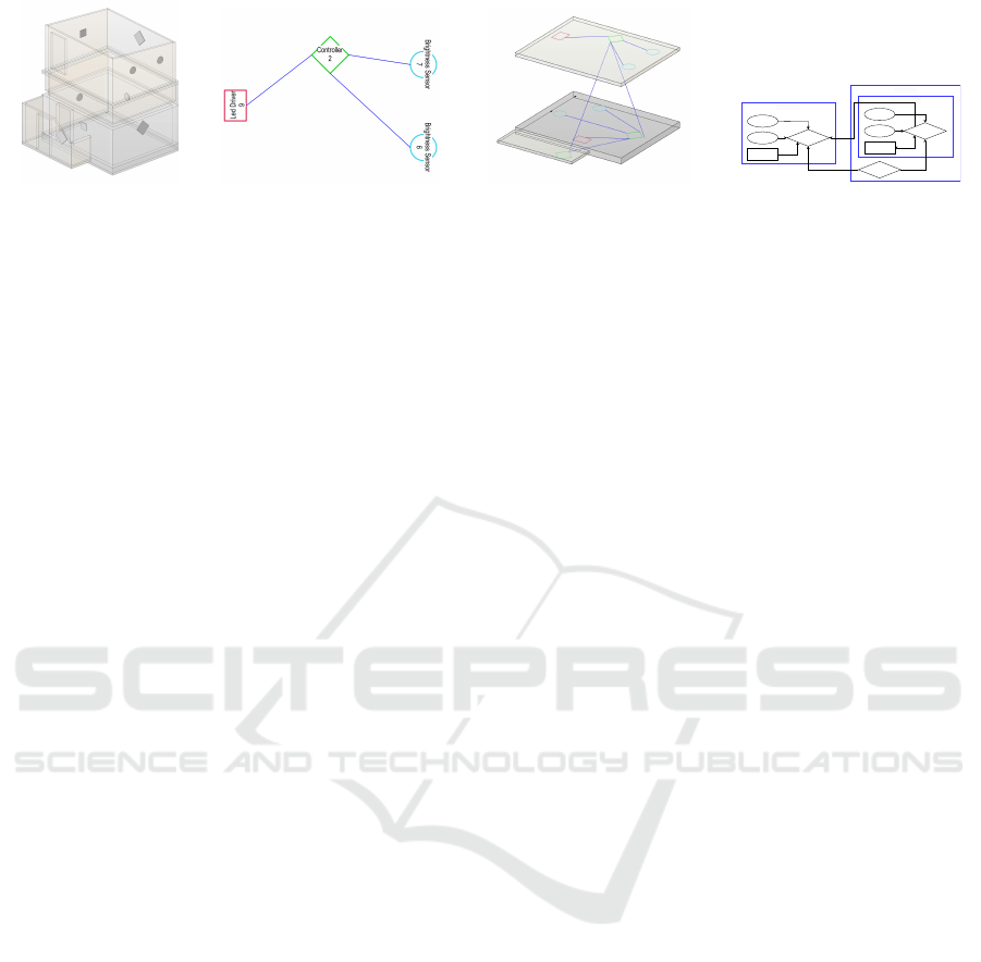
(a) 3D view of a building
with devices (lozenges
denote controllers, cir-
cles sensors, and squares
actuators) placed on dif-
ferent floors.
(b) 2D topology view of the
first floor from the building
from Fig. 3a.
(c) 3D view with walls and doors
hidden showing inter- and intra-
story connection between differ-
ent devices from Fig. 3a.
EG- OK RD
Empfangsraum 2
OG1- OK RD
Sensor: 6
Sensor: 7
Actuator: 9
Controller: 2
Sensor: 5
Sensor: 4
Actuator: 8
Controller: 3
Controller: 1
(d) Exported topology for the
building from Fig. 3d
Figure 3: Example 3D planning views of a building with devices.
5 EVALUATION
We evaluated our proposal using the Technology Ac-
ceptance Model (TAM) (Davis et al., 1989). The
TAM holds considerable importance in the evaluation
of tool utilization by providing a methodical structure
for understanding user perceptions, attitudes, and in-
tentions regarding the adoption of technology.
5.1 Method
From our research questions (c.f. Sec. 2) we created
a user survey (cf. Riemenschneider and Hardgrave
(2001)) to be administered to our sample. The sam-
ple in this case comprises representatives from the
construction domain with both academic and indus-
trial backgrounds. Specifically, after an interactive
tool demonstration, we administered our survey to the
19 representatives, among them researchers (9), light-
ning planners and consultants (6), and building de-
signers (4). The reported average age of participants
is 39,5 years with an average of 9 years of experi-
ence. Two participants did not disclose their gender,
among the remaining 19 participants, there were 14
males and three females.
5.2 Model Evaluation
To thoroughly assess the implementation of our sug-
gested tool environment, we utilize a methodical
approach to estimate and analyze the correspond-
ing structural equation model (Hair Jr et al., 2021).
Structural equation modeling (SEM) is a power-
ful tool for evaluating complex theoretical relation-
ships, especially among latent variables. PLS-SEM is
particularly beneficial in situations where the goal of
the structural model is to predict and explain desired
outcomes, such as technology acceptance (Hair Jr
et al., 2021).
5.2.1 Measurement Model Evaluation
Starting with the evaluation of the dependability and
accuracy of our reflective measurement, as per the ap-
proach outlined by Hair Jr et al. (2021), we analyze
the reliability of each construct by analyzing respec-
tive indicator loadings, (ii) evaluate the reliability of
the measurement instrument by calculating composite
reliability (ρ
c
), Cronbach’s alpha (ρ
T
), and the relia-
bility coefficient (ρ
A
), (iii) assess the convergent va-
lidity by calculating the average variance extracted
(AVE), and (iv), verify the discriminant validity by
examining the Heterotrait-Monotrait (HTMT) ratios.
Concerning (i), all the loadings of the four con-
structs, viz. Training (TRA), Ease-of-Use (EOU), Use-
fulness (USF), and Use (USE), which were measured
reflectively, exhibit statistical significance at a confi-
dence level of CI
α
= .05 or below. Furthermore, being
above the threshold value of .708 (Hair Jr et al., 2021),
they suggest a sufficient level of indicator reliability.
Concerning (ii), all four constructs measured demon-
strate a substantial level of internal consistency, with
ρ
c
, ρ
T
, and ρ
A
all surpassing .7 and slightly exceeding
.95 (Hair Jr et al., 2021). Moreover, w.r.t. (iii), it is im-
portant to mention that all the Average Variance Ex-
tracted (AVE) values significantly surpass the thresh-
old of .5, indicating a high level of convergent valid-
ity for the measures of the four constructs (Hair Jr
et al., 2021). Concerning (iv), all HTMT ratio values
are below the liberal cut-off threshold of .85 (Hair Jr
et al., 2021), indicating discriminant validity among
the four constructs.
5.2.2 Structural Model Evaluation
Having proved the reliability and validity of the con-
structs, we investigate the structural component of
ICEIS 2024 - 26th International Conference on Enterprise Information Systems
126

our instance of the TAM. Following Hair Jr et al.
(2021)’s recommendations, we (i) examine the struc-
tural model for collinearity issues based on the vari-
ance inflation factor (VIF), (ii) assess the significance
and relevance of the structural model relationships,
i.e., the path coefficients, using bootstrapping, and
(iii), assess the explanatory capability of the structural
model using the coefficient of determination (R
2
) and
the effect size ( f
2
).
Regarding (i), the VIF analysis reveals that our
model does not exhibit any evidence of collinearity
among the four constructs, as the greatest VIF values
are well below the threshold of 5 (Hair Jr et al., 2021).
Regarding (ii), we assess the significance and the rel-
evance of the structural model paths by bootstrapping
the sampling distribution to test the structural model’s
relationship coefficients for statistical significance at
CI
α
= .05. Finally, concerning (iii), the R
2
values
for the endogenous constructs USF, EOU, and USE are
moderate being located close to the moderate thresh-
old of 0.5 (Hair Jr et al., 2021). This suggests that our
instance of the TAM has a satisfactory ability to pre-
dict outcomes within the sample (Hair Jr et al., 2021).
5.3 Interpretation of Results
The results of our data analysis have verified the ac-
curacy of our implementation of the TAM and have
shown a significant level of acceptability for the pro-
posed tool environment. Our analysis suggests that
the initial TRA has a significant influence on EOU. To
put it succinctly, being trained in the utilization of a
technology diminishes the level of proficiency needed
to employ it efficiently. Nevertheless, it is crucial to
acknowledge that TRA has an insignificant impact on
USF. This implies that the mere benefit of adopting a
new technology is sufficient for its implementation,
even without any prior training, despite thereby rais-
ing the level of difficulty for newcomers. Based on
these observations, it is evident that the impact of EOU
on USF is considerable. This suggests that possessing
the knowledge of how to utilize a particular technol-
ogy enhances its utility, provided that it is advanta-
geous for the task at hand.
When it comes to the concept of USE, it is evi-
dent that USF has a considerable impact. In addition,
EOU has only a weak influence of USE implying that
ease-of-use fosters technology acceptance but does
not seem to be the driving force behind acceptance.
This reinforces our prior assertion regarding the sole
benefit of adopting a novel technology. Put simply,
the weak impact of EOU on USE serves as more evi-
dence that professionals are eager to embrace a new
technology, regardless of the effort involved, as long
as it is advantageous for their work. Overall, our anal-
ysis demonstrates a robust reception of our proposal
and its modeling methodology.
Regarding RQ1, our proposal effectively show-
cases the utilization of model repositories for model
exchange, model-based development, and language
engineering to advance existing modeling formalisms
towards novel use cases.
As for RQ2, our graphical DSL and its accompa-
nying modeling methodology illustrate the process of
pre-configuring BCS in BIM models. In our current
work, we use this information to subsequently infer a
2D topology (cf. Fig. 3d) as a blueprint for the instal-
lation of the BCS.
Finally, in the event of RQ3, the combination of
model-based development for BCS pre-configuration
and the subsequent capitalization on models for au-
tomatically extracting relevant information thereof
(cf. Fig. 3d) delivers the necessary foundation for es-
tablishing BIM-based DTs in the future.
5.4 Related Work
Tang et al. (2020) - similar to our approach - embed
BCS-specific information into a BIM model. How-
ever, contrary to us, their approach does not support
direct data extraction from the BIM model but instead
leverages the IFC in combination with an additional
tool, thus impeding an integrated workflow. The work
of Dave et al. (2018) describes a concrete implemen-
tation of a framework that integrates IoT and BIM.
Specifically, they export an IFC model from Revit
which is subsequently extended with BCS data for
further use (e.g., visualization). This heavy reliance
on the IFC by export-edit-import however repeatedly
results in errors due to information loss during export
and import and the IFC not being designed for edit-
ing (Mirarchi et al., 2017). Louis and Rashid (2018)
propose to leverage BIM models as operating sys-
tems for smart homes by extending the BIM model
with relevant IoT-device data. By then loading the
model into the Unity Game Engine, they create a plat-
form for click-control of IoT devices in smart build-
ings. Contrary to our work, Louis and Rashid how-
ever only support locating IoT devices in BIM mod-
els but do not address the pre-configuration of BCS
devices (e.g., establishing connections) as done in our
work. Finally, the work of Tan et al. (2022) - similar
to ours - also addresses the configuration of artificial
lighting and daylighting. Yet, in their case models of
the building and embedded BCS are established post
factum only, thus not addressing initial model-based
pre-configuration for initial building operations.
In the event of dedicated language extensions of
Model-Based Auto-Commissioning of Building Control Systems
127

BIM, e.g., by DSLs, the only related work we were
able to identify is by Alves et al. (2017). In particular,
Alves et al. introduce a DSL for embedding real-time
sensor data into BIM models. Yet, their work - similar
to what was discussed previously - neither addresses
pre-configuration nor subsequent model-based auto-
commissioning of BCS.
6 CONCLUSIONS
In our paper, we have presented a metamodel
with relevant tooling support for model-based
pre-configuration of BCS for model-based auto-
commissioning of BCS, a crucial precursor in estab-
lishing DTs of buildings. Our current implementation
allows for both the configuration and extraction of a
structural design plan for operators. The results of
our evaluation using the TAM are promising in that
– despite its for now limited functionality – our pro-
posal is appreciated and will be used once it reaches
the necessary TRL, e.g., TRL7.
In future work, we plan to extend our graphical
DSL to capture further relevant information regarding
auto-connecting, i.e., twinning, physical and virtual
replicas by extracting a device configuration for a DT
middleware that allows for the automated and seam-
less establishment of bidirectional data exchange with
the physical entity. Further, we plan to extend our
proposal by a textual DSL for model-based BCS pro-
gramming thereby also delivering [R5] for eventually
deploying such code-based runtime artifacts.
ACKNOWLEDGEMENTS
This research has received funding from the Aus-
trian Research Promotion Agency (FFG) under Grant
Agreement No.: 898708, TwinLight.
REFERENCES
Alves, M., Carreira, P., and Costa, A. A. (2017). Bimsl: A
generic approach to the integration of building infor-
mation models with real-time sensor data. Automation
in Construction, 84:304–314.
Dave, B., Buda, A., Nurminen, A., and Främling, K. (2018).
A framework for integrating bim and iot through open
standards. Automation in construction, 95:35–45.
Davis, F. D., Bagozzi, R. P., and Warshaw, P. R. (1989).
User Acceptance of Computer Technology: A Com-
parison of Two Theoretical Models. Management Sci-
ence, 35(8):982–1003.
Grieves, M. and Vickers, J. (2017). Digital Twin: Mitigat-
ing Unpredictable, Undesirable Emergent Behavior in
Complex Systems. In Transdisciplinary Perspectives
on Complex Systems, pages 85–113. Springer Interna-
tional Publishing.
Hair Jr, J. F., Hult, G. T. M., Ringle, C. M., and Sarstedt, M.
(2021). A primer on partial least squares structural
equation modeling (PLS-SEM). Sage publications.
ISO (2018). Industry Foundation Classes (IFC) for data
sharing in the construction and facility management
industries — Part 1: Data schema. Standard, Interna-
tional Organization for Standardization, Geneva, CH.
Louis, J. and Rashid, K. (2018). Utilizing building informa-
tion models as operating systems for smart homes. In
Proceedings of the Workshop on Human-Habitat for
Health (H3): Human-Habitat Multimodal Interaction
for Promoting Health and Well-Being in the Internet
of Things Era, pages 1–4.
Mirarchi, C., Pasini, D., Pavan, A., Daniotti, B., et al.
(2017). Automated ifc-based processes in the con-
struction sector: A method for improving the infor-
mation flow. In LC3 2017: Volume I–Proceedings of
the Joint Conference on Computing in Construction
(JC3), pages 491–498.
Ozturk, G. B. (2021). Digital Twin Research in the AECO-
FM Industry. Journal of Building Engineering, 40.
Riemenschneider, C. K. and Hardgrave, B. C. (2001). Ex-
plaining software development tool use with the tech-
nology acceptance model. Journal of computer infor-
mation systems, 41(4):1–8.
Semeraro, C., Lezoche, M., Panetto, H., and Dassisti, M.
(2021). Digital twin paradigm: A systematic literature
review. Computers in Industry, 130:103469.
Tan, Y., Chen, P., Shou, W., and Sadick, A.-M. (2022).
Digital twin-driven approach to improving energy ef-
ficiency of indoor lighting based on computer vision
and dynamic bim. Energy and Buildings, 270:112271.
Tang, S., Shelden, D. R., Eastman, C. M., Pishdad-Bozorgi,
P., and Gao, X. (2020). Bim assisted building au-
tomation system information exchange using bacnet
and ifc. Automation in Construction, 110:103049.
Vieira, R., Carreira, P., Domingues, P., and Costa, A. A.
(2020). Supporting building automation systems in
BIM/IFC: reviewing the existing information gap. En-
gineering, Construction and Architectural Manage-
ment, 27(6):1357–1375.
Wieringa, R. (2014). Design Science Methodology
for Information Systems and Software Engineering.
Springer Berlin Heidelberg.
Zech, P., Fröch, G., and Breu, R. (2024). A requirements
study on model repositories for digital twins in con-
struction engineering. In Cooperative Information
Systems, pages 459–469. Springer Nature Switzer-
land.
ICEIS 2024 - 26th International Conference on Enterprise Information Systems
128
