
Automation of Smart Homes with Multiple Rule Sources
Hoffner Yigal, Kaufman Eran, Avidan Amir, Elad Yovel and Fogel Harel
AI research center, Shenkar College, Israel
Keywords:
Smart Home Automation, Internet of Things (IoT), Rule-Based Smart Home Management, Learning System.
Abstract:
Using rules for home automation presents several challenges, especially when considering multiple stakehold-
ers in addition to residents, such as homeowners, local authorities, energy suppliers, and system providers,
who will wish to contribute rules to safeguard their interests. Managing rules from various sources requires a
structured procedure, a relevant policy, and a designated authority to ensure authorized and correct contribu-
tions and address potential conflicts. In addition, the smart home rule language needs to express conditions and
decisions at a high level of abstraction without specifying implementation details such as interfaces, access
protocols, and room layout. Decoupling high-level decisions from these details supports the transferability
and adaptability of rules to similar homes. This separation also has important implications for structuring the
smart home system and the security architecture.
Our proposed approach and system implementation introduce a rule management process, a rule administrator,
and a domain-specific rule language to address these challenges. In addition, the system provides a learning
process that observes residents, detects behavior patterns, and derives rules, which are then presented as rec-
ommendations to the system.
1 INTRODUCTION
Using rules to automate the control of the home and
its processes poses various challenges. Besides resi-
dents’ rules, most homes are likely to have multiple
stakeholders as additional sources of rules. A stake-
holder is an individual, group, or entity with an in-
terest, involvement, or concern in the smart home,
capable of affecting home-related decisions or be-
ing affected by their outcomes. Stakeholders, such
as the homeowner, local council, the energy supplier,
and the system provider, may also wish to contribute
rules to protect and further their interests. For exam-
ple, local authorities’ rules may reflect home regula-
tions concerning such issues as pollution and permit-
ted noise levels. An energy supplier may have re-
quirements concerning the optimal time to use cer-
tain facilities. The homeowner may wish to keep the
temperature in the house above 5 degrees, no mat-
ter what, to prevent pipes from freezing in the win-
ter. The stakeholders must provide such rules, as they
cannot be learned from observing the residents’ be-
havior.
The presence of multiple stakeholders as rule
providers raises a management problem. Integrat-
ing rules from various sources requires a structured
rule introduction procedure, a relevant policy and a
designated authority, such as a Rule Administrator,
to supervise it. This manager must ensure that the
suggested rules originate from authorized entities and
that any potential conflicts with other rules are ad-
dressed. This aspect of smart home management has
yet to be discussed in the literature.
Another smart home problem concerns the rule
language, which combines two central elements: con-
ditions and decisions. In this approach, conditions re-
fer to the home’s state, its residents’ activities, and
contextual environmental factors. The correspond-
ing actions are typically instructions to activate or de-
activate specific home devices. A smart home rule
language should be able to express automation pref-
erences at a relatively high level of abstraction, en-
abling users to ignore the low-level technical imple-
mentation details and opening up the possibility of the
same rules applying to similar houses. Decoupling
the high-level decisions from the home layout details,
the specific room allocation and the specific device
used from the rules has considerable advantages. For
example, if a rule sets the temperature at a certain
level, this specifies a requirement but does not spec-
ify how to do it. The requirement may be translated
differently, depending on the house and the room’s
40
Yigal, H., Eran, K., Amir, A., Yovel, E. and Harel, F.
Automation of Smart Homes with Multiple Rule Sources.
DOI: 10.5220/0012556300003705
Paper published under CC license (CC BY-NC-ND 4.0)
In Proceedings of the 9th International Conference on Internet of Things, Big Data and Security (IoTBDS 2024), pages 40-52
ISBN: 978-989-758-699-6; ISSN: 2184-4976
Proceedings Copyright © 2024 by SCITEPRESS – Science and Technology Publications, Lda.

characteristics. For example, the required tempera-
ture may be obtained by turning the air conditioner,
activating the ventilator, opening a window, or a com-
bination thereof.
The high-level rules are more likely to be rele-
vant to houses with a similar set-up. For example,
rules defined for a family with kids are likely to suit
other families who live in similar conditions. Such
a scheme would make it easy for stakeholders to ex-
port their rules to different homes. Friends and neigh-
bors would be able to recommend rule scripts to each
other. In addition, the decoupling makes it possible
to change the sensors or actuation devices without
changing anything in the rules.
Our approach addresses those challenges and in-
troduces flexible system management methods and
configurations. A Rule Administrator facilitates
the integration of rules from multiple sources us-
ing a policy-driven rule introduction procedure. Our
domain-specific rule language is designed to abstract
from the specific details of the house configuration
and the devices used, making it sufficiently general to
be portable to comparable homes. Our system also
supports a process that collects data from the system
and uses it to learn the residents’ behavior patterns
and derive rules from them. In addition, the design of
the rule language has important implications concern-
ing the structuring of the smart home system and its
security architecture and implementation.
1.1 Requirements of a
Multi-Rules-Source Smart Home
Several requirements can be derived from the above
discussion concerning the smart home architecture:
• A high-level rule language that abstracts away de-
tails such as room layouts, device configurations,
device interfaces, and access details.
• A translation process from the abstract decision
of the rules to home-specific actions, considering
the home configuration, the available devices and
their interfaces. Similarly, it must support the data
collection, aggregation, and processing of the var-
ious sensors and residents’ input to provide the
relevant information for decision-making.
• A structured and controlled policy-driven rule
suggestion and incorporation process with a dedi-
cated Rule Administrator who will ensure the re-
lated policy guides the process.
• Apart from the resident role, the system should
accommodate various roles. The System Admin-
istrator configures, initializes, and oversees the
computer system’s overall operation, monitoring,
and maintenance. The rule source or owner can
be any stakeholder or an outcome of a learning
process. The Rule Administrator role involves as-
sessing proposed rules from different sources in
the context of system policies, existing rules, and
other relevant considerations.
• Hide the specific protocols of different device
vendors behind a standard protocol.
The structure of this paper is as follows. Section
2 provides an overview of related systems. Section
3 introduces the architecture of our smart home sys-
tems. Section 4 describes the rule language. Section 5
shows how adding, deleting or editing rules are man-
aged. Section 6 describes how rules are derived from
residents’ behavior data. Section 7 discusses the secu-
rity issue which arises from this architecture. Section
8 outlines the implementation of our pilot system.
2 OVERVIEW OF RELATED
SYSTEMS
Many articles focus on monitoring and control tech-
nology by discussing the sensors and actuators con-
nected through a microprocessor-based system. This
approach involves integrating mobile phones with
cloud networking via wireless communication. Users
interact with cloud-based applications through their
mobile devices, which serve as interfaces for moni-
toring and controlling various home appliances. Ba-
sic software facilities provide Some level of automa-
tion to allow the system to make decisions. The
decision-making processes are, in most cases, em-
bedded in the software. Commonly employed con-
trollers for smart home automation systems include
Arduino (Gota et al., 2020), Raspberry Pie (Sharma
et al., 2022), Microchip PIC (Chekired et al., 2021)
and Nod MCU (Bahmanyar et al., 2022). These sys-
tems often provide the resident with a control panel to
manage the house’s devices.
In the architecture proposed by (Xu et al., 2016)
for smart home systems, three levels are identified:
the hardware layer, the controller layer, and the exter-
nal service layer. The hardware layer comprises smart
devices and sensors. The controller layer acts as a
centralized management system, responsible for au-
tonomously perceiving and analyzing user demands
to manage the smart home. The external service layer
integrates existing home service resources, delivering
personalized services to the market. However, the
specific structure of the controller and service lay-
ers, which handle most tasks, remains unclear. The
Software-Defined Smart Home (SDSH) platform is
Automation of Smart Homes with Multiple Rule Sources
41
built upon this architectural framework.
(Singh et al., 2019) propose a secure and effi-
cient smart home architecture based on the cloud
and blockchain technology. The architecture con-
tains four components: smart home layer, blockchain
network layer, cloud computing layer, and service
layer. The Smart home layer comprises many IoT
devices and other subsystems like security systems,
control systems, home theaters, etc. In the Distributed
blockchain layer, devices are managed by transactions
and stored in the local blockchain. The Cloud layer
provides services or applications. The service layer
interacts with the service providers and smart home
users. It focuses on application services offered by
the cloud platform. Users use services or applica-
tions provided by smart home clouds, enterprise pub-
lic clouds, or other third-party clouds.
(Mokhtari et al., 2019) present a cost-effective and
scalable Smart Home Systems (SHSs) architecture
using microcontrollers for remote automation and
control of home appliances. The architecture com-
prises several layers: the Physical layer with various
sensing technologies, the Fog-computing layer for ba-
sic data processing, the Network layer with gateways
and communication protocols, the Cloud-computing
layer for extensive processing and data communica-
tion, the Service layer offering operational and ana-
lytical data views, the Session layer facilitating data
exchange between services, and the Application layer
housing subscribed applications for data-driven ser-
vices.
(Burhan et al., 2018) propose a three-layered ar-
chitecture. The Perception Layer identifies and gath-
ers information from physical objects; the Network
Layer serves as a bridge between the perception and
application layers by transmitting collected informa-
tion; and the Application Layer encompasses various
applications utilizing IoT technology, such as smart
homes, cities, health, and more, providing services to
these applications. (Jaouhari et al., 2019) propose a
similar architecture consisting of the Device, Gate-
way, and Application and Service layers.
All the layered architectures mentioned above de-
scribe the infrastructure of the smart home systems
without providing any help in structuring the appli-
cations or the services they are supposed to support.
As significant as the infrastructure is for smart home
systems, the main challenge is the application’s de-
sign. This is where our architecture and pilot smart
home system differ: it offers a way to structure the
system, not from an infrastructure point of view but
from the application point of view. Furthermore,
dividing the space between the rules and the sen-
sor/actuator devices into generic and concrete layers
enables expressing the house rules in a device and
house configuration-independent manner.
There are many articles about using rules for au-
tomating smart home decisions. Still, they ignore
the possibility of multiple rule owners, the issues sur-
rounding the management of the rules and how they
interact with the rest of the system. Our approach
deals with this issue and considerably influences how
rules are introduced into the system.
3 THE SMART HOME
ARCHITECTURE
The structure that underlies the architecture of our
smart-home system is based on two ideas:
• Separation of Concerns: a design principle that
manages complexity by partitioning the system
into layers so that each layer is responsible for a
different concern or set of concerns. Each layer
has its decision-making process and is also re-
sponsible for aggregating the data and manipulat-
ing it to be used in the decision-making process.
• Use of Feedback. Feedback refers to gathering
data about a system’s state or performance and
then using it to make adjustments or corrections
to the system. It helps maintain and improve the
system’s performance.
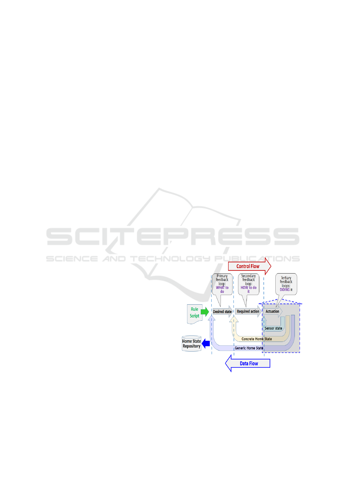
Figure 1: The layered architecture of the smart-home sys-
tem with three levels of feedback loops.
The two ideas are combined to create a layered
structure, where each layer consists of a feedback
loop that encloses the next layer, as shown in Fig-
ure 1. Each enclosing loop gets data from its inner
IoTBDS 2024 - 9th International Conference on Internet of Things, Big Data and Security
42
layer and additional sensors for its decision-making
and uses this data to make decisions for the enclosed
loop. Each layer has its own knowledge and respon-
sibility. This results in the following feedback loops
and subsequent layers:
• The Primary Outer Loop. determines what should
happen by using the rules to decide on the desired
state of things.
• The Middle Secondary Loop. determines pre-
cisely what action should be taken based on the
decision made by the outer loop and by which de-
vices.
• The Tertiary Innermost Loop. activates the appro-
priate devices if so decreed by the secondary en-
closing loop.
The result is a three-layered architecture of the smart-
home system, as shown in Figure 1.
There is two-way traffic between the layers: de-
cisions flow in one direction and ultimately cause ac-
tions to be taken at end-point devices; data flows from
the sensors and is aggregated and processed to create
different views of the state of the home.
The three-layered architecture of our smart-home
system uses two interdependent channels that flow in
opposite directions through its layers: the data flow
and the control flow channels.
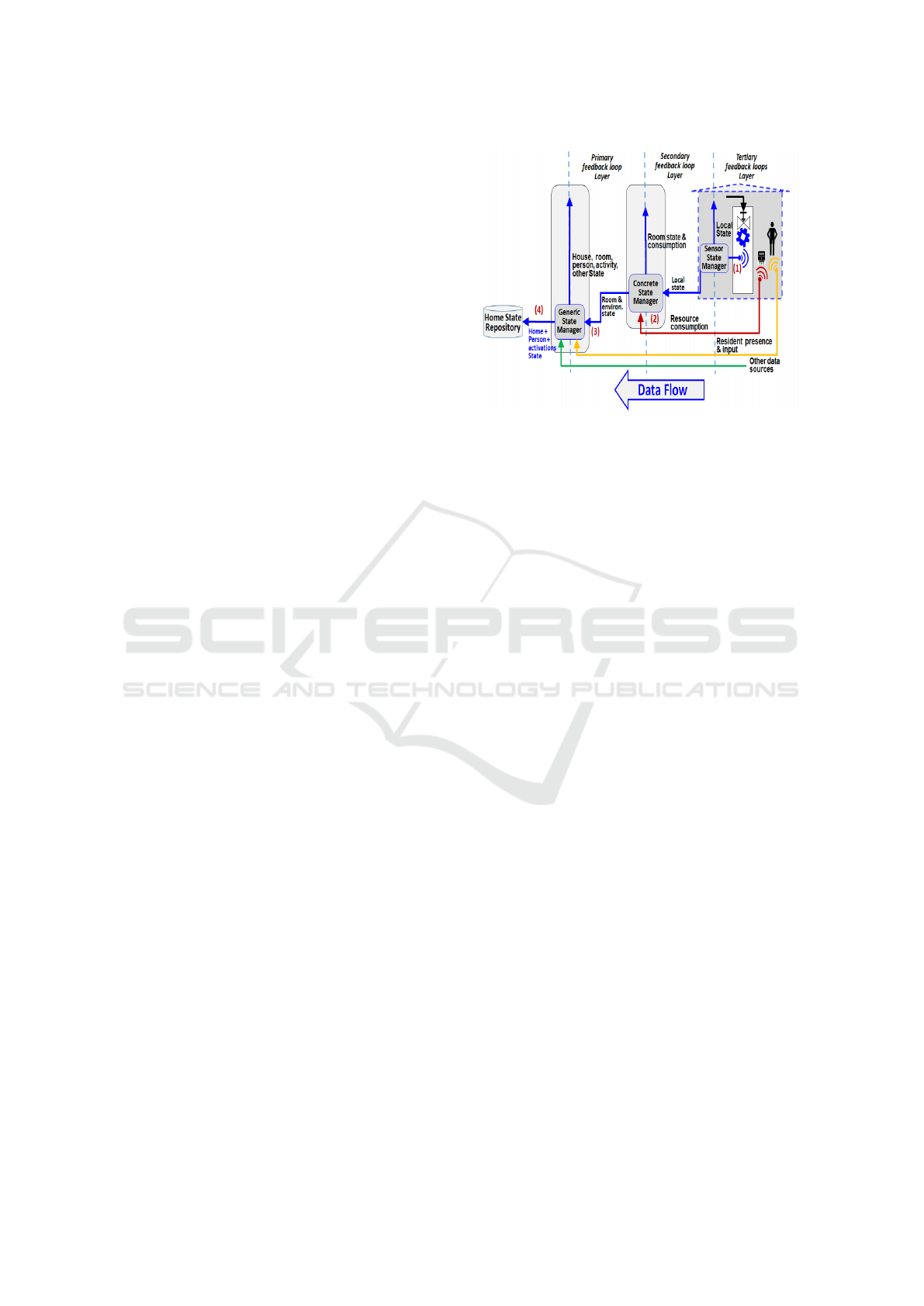
3.1 The Data Flow Channel
The data flow channel (Figure 2) transforms the data
from the sensors to the appropriate level of abstrac-
tion so that the decision-making process of the control
flow channel can use it. Thus, the data flow channel
aggregates and analyzes data from sensors and other
sources, such as residents’ audio input. It transforms
individual data points into progressively more com-
prehensive views of the system, going from the status
of a sensor to the condition of a room and, ultimately,
to the overall state of the house and its current occu-
pants’ activities.
The data flow channel comprises state-making
managers, progressing from sensors to the Sensor
State Manager, to the Concrete State Manager, and
finally to the Generic State Manager. These man-
agers play a central role in furnishing relevant data
for the decision-making processes of the control flow,
as shown in Figure 3:
1. In the tertiary feedback loop, the sensors provide
data for the local Sensor State Manager process
to close the immediate feedback loop. A compar-
ison of the set point of the loop with the current
sensor value is used to decide whether to activate
the connected actuator. At this level, the tertiary
Figure 2: The Data Flow channel, showing the stages that
transform the data from the sensors into more comprehen-
sive views of the system.
feedback loop does not know which room it is in
or who is in the house; its sole responsibility is to
reach and hold the set point dictated by its outer
loop – the secondary layer. An example could be
the room or the boiler’s water temperature or the
ultraviolet level in the room.
2. The Concrete State Manager is responsible for ag-
gregating the data from the tertiary layer Sensor
State Manager and data about resource consump-
tion from various meters. The process involves
the Concrete Home Manager mapping devices to
rooms, thereby putting together the state of rooms.
At this level, the data passed to the Generic State
Manager is, for example: Temperature in RoomX
is 25.
3. The Generic State Manager collects the data from
the previous state managers together with data
about the presence of residents in the house and
some data about their activities. This is processed
to create a high-level view of the state of the
house, the persons present, which room they are
in, and what activity they engage in.
4. The data from the Generic State Manager is fed
to the Generic Home Manager and also sent to
a Home State Repository for subsequent uses,
which will be discussed later.
3.2 The Control Flow Channel
The control flow channel (Figure 3) comprises stages
that make the appropriate decisions at each layer so
that ultimately, the appropriate devices will be acti-
vated or deactivated based on the rule script and the
state of the home. The Generic Home Manager con-
sists of an Interpreter who can execute the rules in the
Automation of Smart Homes with Multiple Rule Sources
43
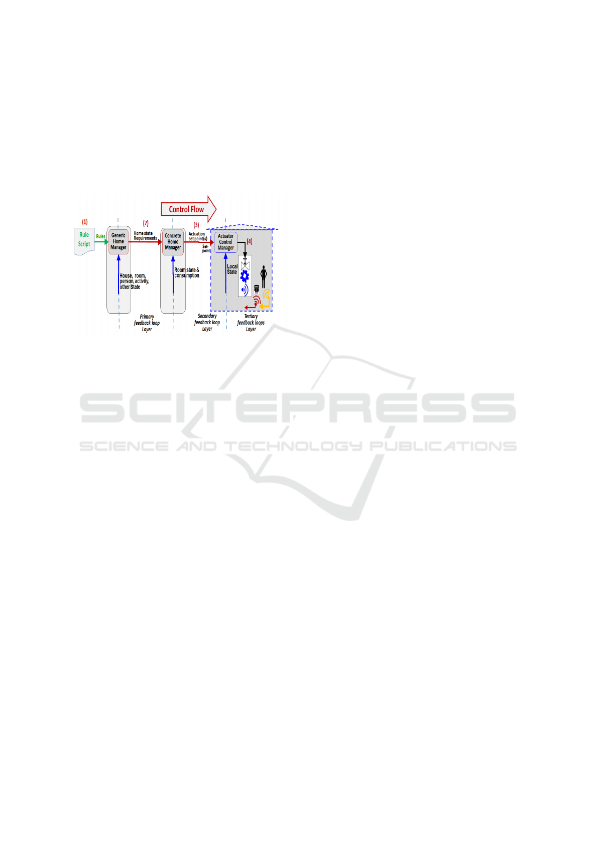
rule script, thereby determining whether a home state
change should be made. These decisions are passed
to the Concrete Home Manager, ultimately becoming
actions through the Actuator Control Manager. Those
decisions flow from the high-level layer to the low-
level ones, from ‘What to do’ to ‘How to do it’ and to
‘Doing it’ - where each layer adds its relevant knowl-
edge to the decision-making process.
Figure 3: The Control Flow channel and the translation be-
tween the layers going from the rules, through the decisions,
to the activation of devices.
The following are the stages of the control flow
channel:
1. The primary feedback loop - the Generic Home
Manager uses the rule script and the information
from the Generic State Manager to determine if
the state of the house needs changing.
2. The state request is transferred to the Concrete
Home Manager. It translates the request into com-
mands to specific devices or devices.
3. These commands can take one of two forms: as
direct instructions to switch a device ON/OFF, for
example, or as a set point or range to local feed-
back loops of the tertiary layer.
4. The tertiary layer is a local feedback loop that is
responsible for keeping the set point it received
from the Concrete Home Manager.
3.3 Combining the Data Flow and
Control Flow Channels
By combining the data and control flows, we arrive at
the smart home architecture shown in Figure 4. The
data channel feeds the control channel with the infor-
mation needed to make the decisions and the trans-
formations in the Generic and Concrete Home Man-
agers. Each engulfing feedback loop manages its in-
ner feedback loop.
To explain how the architecture operates, we use
an example of how rules work in the system. Given
the following rule in the rule script that has been given
to the Generic Home Manager to be executed by its
Interpreter:
IF Joe IN Home AND SUMMER AND MORNING
THEN KEEP JoeRoomTemperature BETWEEN 21
23
• In the primary layer, data about whether Joe is in
the house comes from sensors or from input from
Joe. This data is passed to the Generic State Man-
ager.
• Other data sources, such as the date, time of day,
and whether the day is a normal day, weekend day
or holiday, are also passed to the Generic State
Manager.
• When the condition of the above rule is evaluated
to TRUE, the command:
KEEP JoeRoomTemperature BETWEEN 21 23 is
sent from the Generic State Manager to the Con-
crete State Manager.
• In the secondary layer, the Concrete State Man-
ager knows which room belongs to Joe and what
devices are present. The request is translated to
a set point to the cooling system to set the room
temperature to 23.
• The set point is sent to the specific Actuator Con-
trol Manager responsible for the cooling system.
If the current set point of the air-conditioning sys-
tem is already set to 22 degrees, no action is taken.
• In the tertiary layer, if the cooling system is not
self-regulating, a temperature sensor in the room
will be used as part of a feedback loop. The cur-
rent temperature will be compared to the set point
given by the Concrete State Manager, and the dif-
ference will be used to decide whether to switch
the cooling system. This will be the setup until
conditions change and another rule is triggered.
In a more complicated scenario, the Concrete
State Manager knows that the window shutters are en-
tirely open and decides to set the temperature to 23
and close the shutters a bit.
3.4 Management of End-Point Devices
The Concrete Home Manager takes the high-level re-
quirements from the Generic Home Manager and de-
cides how to achieve them. Once the decision about
which devices to activate is made, the Concrete Home
Manager passes the request through the specific pro-
tocol to the selected device. Different devices will
IoTBDS 2024 - 9th International Conference on Internet of Things, Big Data and Security
44
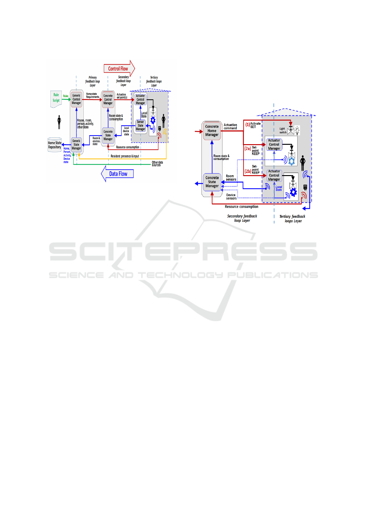
Figure 4: The overall architecture of the smart home system
shows both control flow and data flow channels.
likely have their own protocol, as standards are slow
to emerge or to be adopted in this domain.
In addition to the different protocols, actuator de-
vices can have different management configurations,
as shown in Figure 5, depending on whether there is a
feedback loop that can continue to monitor the desired
state:
1. SET - By Direct Command. Devices whose states
are discrete can be set to a particular value by di-
rect command. Examples are simple lights, venti-
lators, or laundry machines with on/off states. The
command SET is used in this case. It expresses
the discrete nature of the device it activates:
IF Joe IN Home THEN SET JoeRoomLight ON.
IF AT NIGHT THEN SET ExternalDoors
CLOSE.
IF Joe IN Home AND Joe ACTIVITY IS Music
THEN SET JoeRoomMusic ON
2. KEEP - By Desired Set Point. Devices that control
some variable that does not have a discrete value,
such as temperature or humidity. Such devices re-
quire a feedback loop to reach and maintain the
desired value provided by the set point. The com-
mand KEEP is used for this case. It expresses the
requirement that a certain state is to be kept, using
feedback, even if it drifts from the required value
or range. There are two possible configurations
in this category: devices whose feedback loop is
already included as part of the device (Figure 5
(2a)) and devices whose feedback loop has to be
constructed around the device (Figure 5 (2b)). Ex-
amples of the former are current air-conditioning
systems with a feedback loop that maintains the
required temperature given as a set-point input.
Examples of the latter are humidity control or UV
light control.
IF Joe IN HOME THEN ‘KEEP JoeRoomTem-
perature BETWEEN 23 21’
Figure 5: Different management configurations of the actu-
ator devices using the SET and KEEP commands.
Manual Overriding of Home State. There are sit-
uations where the residents wish to change the state of
the home directly, possibly overriding the current set-
tings. Such requests should enter the system through
a special interface, such as a smartphone, connected
to the Concrete Home Manager. This ensures that the
user cannot access a specific device but only specify
a desired state of some measured variables. This is
further explained in Section 7.2. If the system in-
cludes a resident behavior learning component, then
the changes should be monitored and recorded in the
Home State Repository. If such actions persist, they
are likely to result in modifying the rules.
4 THE RULE LANGUAGE
The majority of rule-based systems adopt Trigger-
Action programming paradigm in the form of:
”IF a trigger occurs WHILE conditions are true,
THEN take some action” (Zhang et al., 2020; Ghiani
et al., 2017; Ur et al., 2014).
Our rule language basic structure is a simpler con-
ditional statement of the form:
IF referral to Measured variables THEN referral to
Control variables. This ties together the data-flow
and the control-flow channels as shown in Figure 6.
Automation of Smart Homes with Multiple Rule Sources
45
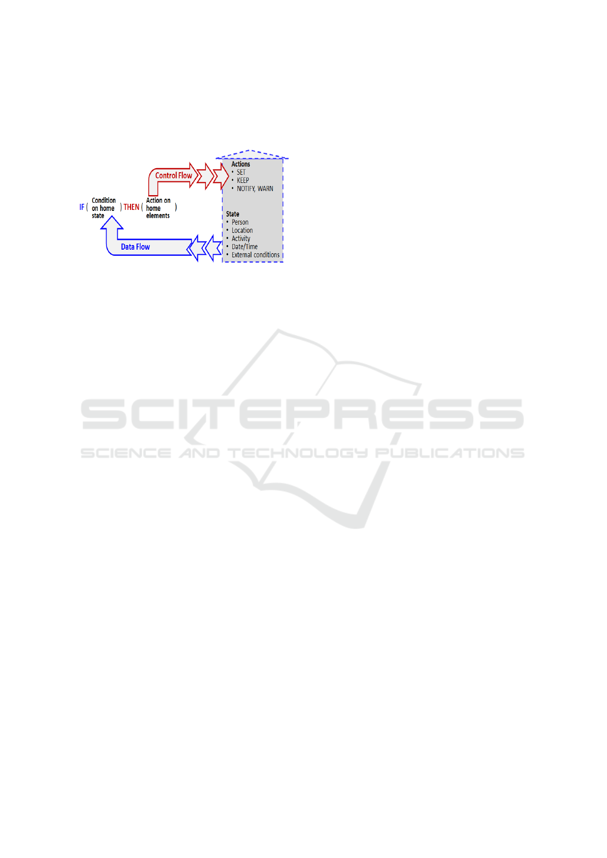
The condition depends on the data supplied by the
data-flow channel, and the decision sends a command
to the next layer to act, thereby connecting to the
control-flow channel.
Figure 6: The relationship between the data and control
flow channels and the components of the rule.
The central idea of our language is to keep it suffi-
ciently abstract so that the rules will be easily transfer-
able from one household to a similar one. While our
rule language focuses on private homes, our approach
can be applied to other domains, such as offices, hos-
pitals and schools. While some keyword overlap is
likely, each domain will also have its own special key-
words. Schools will likely require keywords for class-
rooms, a staff room and an Office; Hospitals will need
keywords for departments, patient rooms, receptions
and laboratories.
The fundamental elements of our rule language in-
clude:
• Domain Specific Keywords. Reserved words with
specific meanings are part of the language’s syn-
tax. The keywords in our rule language can be
divided into several categories: Location, Role,
Resident, Activity, Date/Time/Event and Action.
There are two main sources of keywords:
– System Default Keywords. These items are ex-
pected to be present in almost every house and
are therefore provided as default words. This is
likely to make the rule scripts more transferable
and readable.
– User-Defined Keywords. Stakeholders can add
keywords if they fit the particular circum-
stances of their homes.
The keywords can be divided into several cate-
gories:
– Location. A place inside or outside the house.
Private home defaults can be Home, Kitchen,
LivingRoom, BedRoom etc. and special terms
like AllRooms : Home, Kitchen, Living room.
Other user-specific locations in the system can
be added by a user to the application by clicking
’add location’ and adding the chosen name of
the room. Rule condition example:
IF Joe IN Bathroom AT NOON
– Role. A person related to the house with a
set of responsibilities, accountabilities, liabili-
ties, and permissions granted through the secu-
rity setup (see section 7). These could include
Resident, Homeowner, CleaningPerson, Main-
tenancePerson and EnergySupplier defaults. A
user can add other users to the system by click-
ing ’add role’ with the name, phone number and
other identification.
Rule example:
IF CleaningPerson IN Bathroom THEN SET
LightSET IN Bathroom ON.
– Resident. These are the specific names of
the house’s residents. Examples: Joe, Ruth,
Spencer
– Activity. These activities are common in houses
and related to a person or persons. Activities
can be Sleeping, Resting, Exercising, Working,
etc. User-specific activities may be added. Rule
example:
IF Anyone IS Sleeping THEN SET AllVolume
Below 25
– Date/Time/Event. These are indications of time
or events that make a difference in the resi-
dents’ behavior.
System default:AM, PM, Morning, Afternoon,
Evening, Night, Holiday, Xmas, Easter, Week-
end, Today, Tomorrow, Minute, Hour, Day,
Week, Month, Year, Always
– Action. These commands result from decisions
made by the THEN part of a conditional state-
ment. System default actions: SET, KEEP, ON,
OFF, CLOSE, OPEN, NOTIFY, WARN.
Warnings and notifications are special cases of
action. This is relevant when the residents
should be made aware of the state of the house.
Security-related notifications are one example
of such warnings.
For example, the rule:
IF Anyone IN Home AND AllTenants NOT IN
Home THEN WARN Joe. The first part of the
conditional statement could be, for example,
triggered by a motion detector and the second
part by locating the residents’ phones.
• Variables. Variables are used to store and repre-
sent data in a system. They have names and data
types, and their values can be changed during the
system’s lifetime. There are two types of variables
in our system:
– Measured Variables. These variables depend
IoTBDS 2024 - 9th International Conference on Internet of Things, Big Data and Security
46
on the specific things that are of interest and
can be measured in a home. Ultimately, each
item is linked to one or more sensors or input
devices, but the rule language does not have to
be aware of the sensors or input devices, only
the data provided by the data flow channel. By
agreed practice, such variables have the postfix
VAL.
Examples: TemperatureVAL, HumidityVAL,
UVLevelVAL, WindowVAL, SmokeVAL.
Rule example:
IF TemperatureVAL IN Kitechen ABOVE 25
THEN
– Controlled Variables. These variables depend
on the things that can be actuated in a home
either by direct command or set-point input
to a feedback loop. By agreed practice, such
variables have the postfix KEEP or SET.
Examples: TemperatureKEEP, Humidi-
tyKEEP, UVLevelKEEP, DoorLockSET,
LightSET, LaundryMachineSET.
• Operators. Operators perform operations on vari-
ables and values.
– Relational Operators. EQUAL, ABOVE, BE-
LOW.
– Logical Operators. AND, OR, NOT.
• Control Structures. Control structures determine
the flow of execution shown in figure 6.
Rule example:
IF referral to Measured variables THEN referral
to Control variables
5 THE RULE MANAGEMENT
The Rule Script Manager shown in Figure 7 is con-
cerned with adding, editing or deleting a rule in the
Rule Script that is ultimately executed by an Inter-
preter in the Generic Home Manager. This process
has a Rule Management Policy and a Rule Adminis-
trator associated with it that determines the following
things:
• Permissions. Specifies which users are authorized
to view the home state variables and request a
change of control variables as written in the rule.
• Conflict Resolution Procedure. The procedure for
resolving conflicts (Carreira et al., 2014) can in-
clude the following: dropping the rule, sending a
warning back to the source, or referring the reso-
lution to a higher hierarchy. This will be further
explained in Section 7.3.
• Rule Script Update. The point at which it is possi-
ble to replace the rule script of a working system
with an updated one.
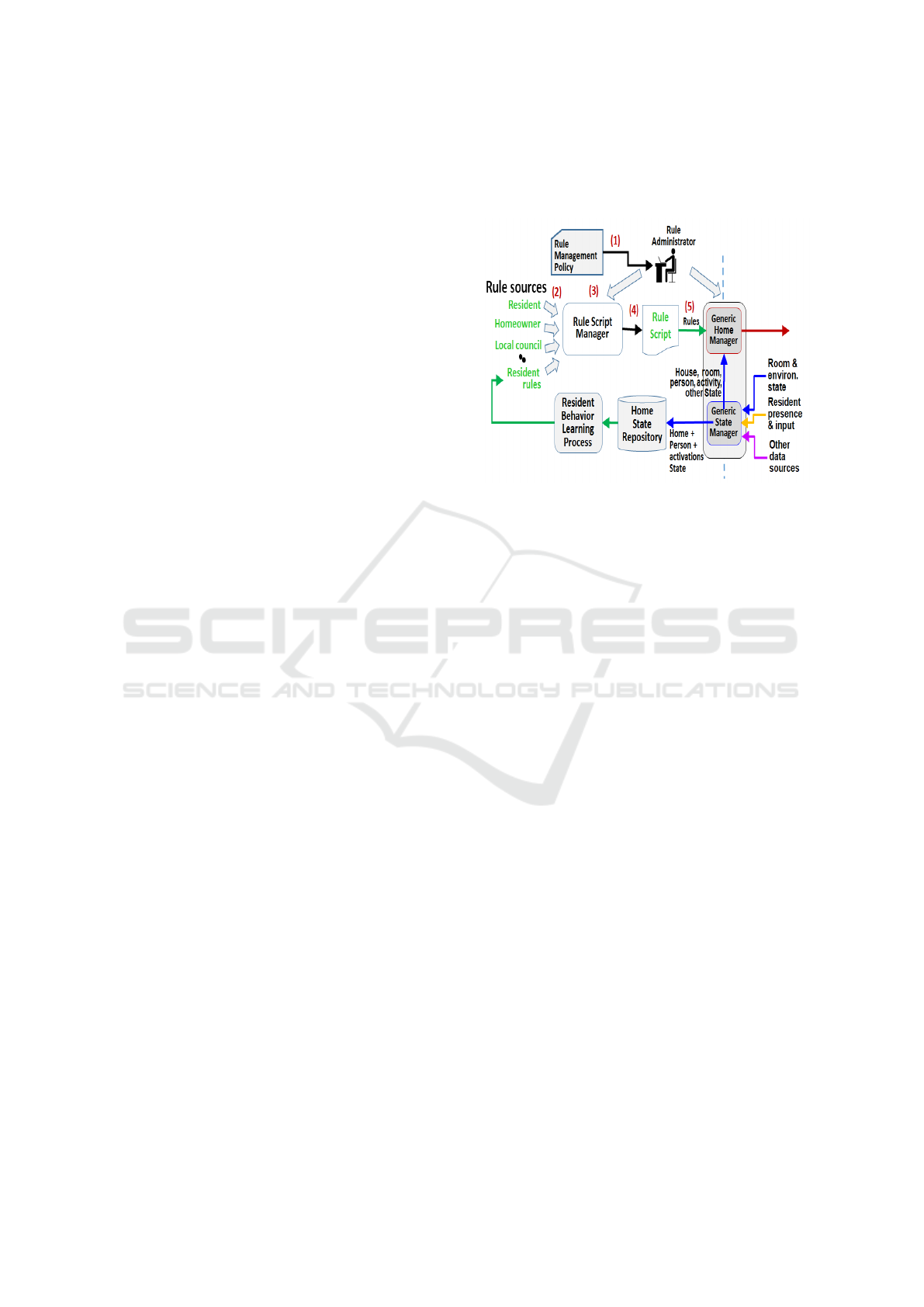
Figure 7: The Rule Management Policy determines how to
deal with any rule proposals from the various stakeholders.
Figure 7 is an example of the rule management
process when a rule recommender tries to add a new
rule to the rule script:
1. The administrator gives the rule management pol-
icy to the Rule Administrator.
2. One of the authorized stakeholders suggests incor-
porating a new rule into the rule script.
3. The Rule Administrator uses the Rule Script Man-
ager to check the rule from several points of view:
• The rule has the correct syntax.
• The stakeholder is authorized to read from and
write to the designated devices according to the
policy.
• The new rule does not conflict with an existing
rule in the currently executing script; if it does,
the Rule Administrator resolves it according to
the conflict resolution given in the policy.
4. The rule is added to the home rule script.
5. At a quiescent point in the running of the Generic
Home Manager Interpreter, the new script re-
places the old one, according to the rule update
policy.
The Rule Script Manager shown in Figure 7 can be
implemented differently, depending on the system’s
goal. The two extreme points on the spectrum of pos-
sible designs are:
• Complete Human Control. This would require an
interface that presents the new rule to the Rule
Administrator, who has complete control over the
process.
Automation of Smart Homes with Multiple Rule Sources
47
• Maximum Automation. This would require em-
bedding the policy and the process in software.
Nevertheless, this solution must still provide a
minimal interface to the Rule Administrator in
case of problems that the automation cannot re-
solve.
If the implementation is automated, then a security
mechanism should be in-place. This issue is elabo-
rated upon in section 7.
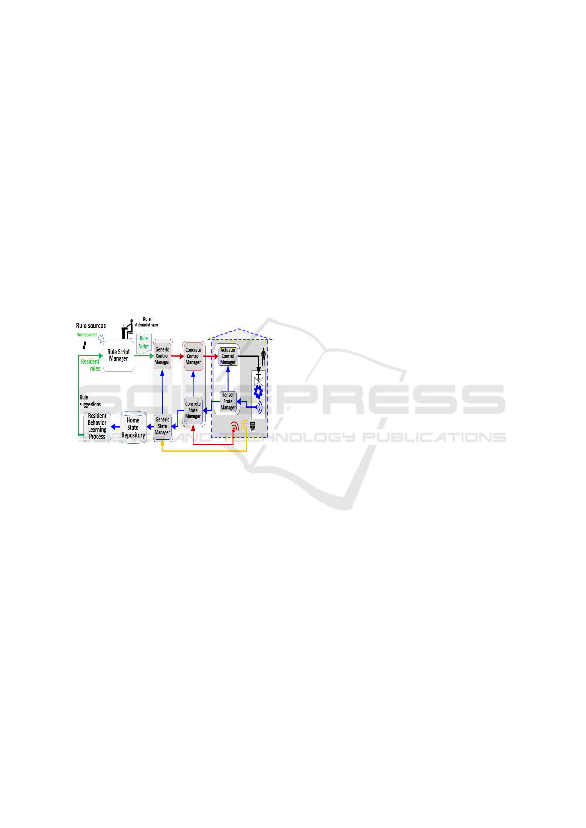
6 THE LEARNING PROCESS
The purpose of the learning process is to derive rules
in the language defined in section 4, based on the res-
idents’ activities in the house. The learning process
can act as a source of rules for the rule management
process, as shown in figures 7 and 8.
Figure 8: Closing the loop with data analysis such as the
learning process.
6.1 Our Learning Process
Implementation
In our implementation, we used Markovian belief nets
to capture context-aware reasoning. The house has
two main components: measured variables and con-
trolled variables. These two components are intri-
cately connected through the user’s activity and pro-
vide formal reasoning of the form:
’IF SENSOR
1
EQUAL 5 and SENSOR
2
ABOVE
25 THEN SET ACTUAT OR
1
ON and KEEP
ACTUATOR
2
ABOVE 25 ’.
6.2 Reasoning Premise
Our premise is that the house rules follow the argu-
ment that sensor readings always cause device actua-
tion and are not the effect. For example, the presence
of a person in a room is the reason for the light being
turned on, not the other way around. The exception
is when sensors measure the state of the actuator for
control reasons, in which case those sensors are con-
sidered part of the actuator. For example:
’IF HumidityVAL ABOVE 15 THEN SET Irrigation-
SET ON’ and never:
’IF IrrigationSET ON THEN HumidityVAL is
ABOVE 15’. Time is always the cause, so:
’IF 2AM THEN SET Laundry ON’ and : ’IF Laundry
ON THEN 2 AM’.
The reasoning premise is encoded into the Marko-
vian network structure. The actuator’s state is being
reported along with other residual sensed parameters
such as heat, humidity, presence etc. By using rein-
forcement learning, the connections that co-occur at
a certain time were strengthened while others were
weakened. For example, every time Joe is in a room
and the room temperature is above a certain degree,
Joe turns on the AC at a preferred level. In this exam-
ple, the activation of the AC co-occurs with the rel-
evant measured variables, such as humidity and tem-
perature, with high probability, while other measured
variables, such as light or pressure, act as noise for
this actuator’s state.
6.3 Markovian Networks Background
A Markovian network for a set of variables X =
{X
1
, ..., X
n
} is the pair (G, θ) over X, where G is a
directed acyclic graph with n nodes, one for each vari-
able in X, called the network structure, and θ is a set
of conditional probability functions, called the net-
work parametrization.
Each variable only directly depends on its prede-
cessor in the sequence. For each variable, its parame-
ter is the set of conditional probability functions of the
variable given each value of its parents in the graph.
According to the type of random variable, three types
of Bayesian networks are distinguished: discrete if
the variables are discrete, continuous if the variables
are continuous, and hybrid if there are both discrete
and continuous variables in the network.
In our model, a hybrid network is considered.
The graph encodes a set of conditional indepen-
dence assumptions called local independence: Each
variable X
i
is conditionally independent on its non-
descendants given its parents in the graph. An impor-
tant result is the chain rule, which states that:
P(X
1
, . . . , X
n
) =
∏
P(X
i
|Pa(X
i
)) (1)
where Pa(X
i
) are the parents of X
i
in the graph.
This method states that given a data set of instanti-
ations of the variables in a discrete Bayesian network,
each probability of the parameters is estimated with
IoTBDS 2024 - 9th International Conference on Internet of Things, Big Data and Security
48

the formula:
θ
x
i
|pa(x
i
))
=
D(x
i
, pa(x
i
)
D(pa(x
i
))
(2)
where D(x
i
, pa(x
i
)) is the number of cases in the
dataset that contain the instantiation x
i
of X
i
and
pa(x
i
) of its parents Pa(Xi); and D(pa(x
i
)) is the
number of cases in the data set that contain the in-
stantiation pa(x
i
) of Pa(Xi). Once the Bayesian net-
work has been designed, i.e., the structure and param-
eters have been specified, the objective is to obtain
information by answering questions about the vari-
ables and their probabilities. The techniques used are
known in general as inference. Given a Bayesian net-
work for a set of random variables X = {X1, ..., X n}
these inferences are:
• Probability of Evidence: P(Xi = xi) ∀x
i
∈
{0, 1}, i ∈ {1, . . . , n}.
• Posterior Marginals: Let X
j
= x
j
, be evidence
of the Bayesian network, posterior marginals
are P(X
i
= x
i
|X
j
= x
j
) ∀x
i
∈ {0, 1}, ∀i ∈
{1, . . . , j − 1, j + 1, . . . , n}.
• Most probable explanation: Let X
n
= x
n
, be evi-
dence of the Bayesian network, most probable ex-
planation are x
i
∈ {0, 1}, ∀i ∈ {1, . . . , n − 1} such
that P(X
1
= x
1
, . . . , X
n
= x
n
) is maximum.
6.4 From a Network to a Rule Language
In our case, we used the posterior marginal between
sensors and actuators to create new rules. We used
a very simplified architecture in our implementation,
where the sensors are fully connected and directed to
all actuators. Other structures can be considered in-
volving latent variables, which may represent certain
learned latent states.
When a certain threshold of the joint probability
is reached, a recommendation connecting these pa-
rameters appears. The system will update these prob-
abilities (online learning) when new data becomes
available, ensuring that the system’s recommenda-
tions evolve over time and adapt to changing condi-
tions.
If the user regards this rule as being unwanted,
then the threshold is raised so the rule does not ap-
pear again in the recommendations system. This indi-
cates that the consistency for this activity needs to be
stronger in order for it to be reaffirmed.
7 SECURITY AND PRIVACY
One of the innovative principles of our design is the
way access control is used to determine whether a
specific user can or cannot view some measured vari-
ables or manage the state of some controlled vari-
ables. In our approach, there is no direct reference
to concrete devices. Instead, the user specifies the
desired state of some controlled variable, which the
Concrete Control Manager translates to specific de-
vice activation. The result is that access control is
done based on state requests rather than direct access
requests to devices. Thus, there is no need to specify
device access permissions for access control. For ex-
ample, if a user wants to change the temperature of a
room that does not belong to her, the access control
process would refuse to authorize it.
7.1 Related Work
In order to tackle the security attacks that threaten the
privacy and safety of the smart home, several architec-
tures have been proposed. (Park et al., 2016) presents
a traffic monitoring and inspection solution called
IoTGuard. All traffic is routed to the IoT Controller
and linked to each IoT device with the IoT Watchdog
in order to target and monitor particular IoT devices
using device-specific IoT protocols. The Intrusion
Detection System (IDS) framework of (Pacheco and
Hariri, 2016), is based on Anomaly behavior analysis
and tries to provide security by monitoring the traffic
that runs through the main gateway.
The work by (Rafferty et al., 2018) relies on
Agent-based modeling, where agents inside the smart
home environment make observations and implement
the intended behavior. This model requires minimal
user engagement and is focused on threat detection.
Habibi et al., (Habibi et al., 2017) proposed a
whitelist-based intrusion detection technique specific
to IoT devices. The proposal aims to prevent IoT de-
vices from getting entangled in botnet activities, so it
blocks DNS lookups to malicious sites at the gateway
level.
Serror et al. (Serror et al., 2018) follow a rule-
based approach, where every IoT device is allowed a
specific behavior, namely the specific set of allowed
connections, in order to fulfill its intended function-
ality. The gateway enforces these rules with traffic
filtering and anomaly detection techniques.
7.2 Our Security Approach
The smart home is a distributed system, so each mod-
ule should employ the minimum trust policy. In other
words, communication should be encrypted, users
should be authenticated, and actions authorized using
a suitable policy. This follows along the lines of the 3
A’s of the golden standard for access control: authen-
Automation of Smart Homes with Multiple Rule Sources
49

ticate, authorize, and audit.
As mentioned in section 5 - a rule management
policy is made out of the following:
• Permissions
• Conflict resolution
• Rule update
The Concrete State Manager serves as a gateway
connecting to the outside world and abstracting the
local home devices and their proprietary protocols,
which reside inside a local net.
Permissions are related to users and states through
the Access Control Lists (ACL). The ACL is made out
of state users and their related actions, for example:
State User Action Value
Temperature Resident Read All
Temperature Resident SET ABOVE 5
Lights Resident Read & SET Any
Temperature Owner Read & SET Any
Lights Owner Read & SET None
The security modules are therefore made up of
two main components: the Authentication Service
(AS) and the Access Control Service (ACS).
The Authentication Process. Authentication can
be done via different schemes, such as passwords,
second-factor authentication, etc. This service can
also be a third-party service. The AS grants a ticket
signed by the AS private key to the client, which
serves as a client certificate for all the following ac-
tions. The AS signs the user IP (and/or associated
domains) and user name (as it appears in the ACL)
with a time stamp, expiration date, and a nonce.
The Authorization Process. The client sends a re-
quest to the ACS using the certificate granted by the
AS which verifies his identity.
The ACS verifies the AS signature of the client
certificate and uses the ACL to grant a ticket for the
requested state’s read or modify according to the pol-
icy with the user’s credentials signed by its own pri-
vate key.
The signature holds the user IP (and/or associated
domains) and user name (as it appears in the ACL),
the desired state name (as it appears in the ACL) and
the requested action (read or set).
Stakeholders have two main ways to access home
devices:
• Overriding Current Home State. Using remote ac-
cess with a tablet or smartphone in order to change
the state of one of the home-controlled variables,
such as temperature or lighting, as a ’one-off’ re-
quest. The request goes to the Concrete Home
Manager after getting a ticket from the authoriza-
tion process. The Concrete Home Manager guard
validates their ticket using the ACS public key. It
then translates the requested state change to the
activation of the necessary device and activates
the selected device through its proprietary API.
• Adding a Rule to the Rule Script. Requesting
a conditional change to one of the states of the
house. This is done through the rule-management
process.
When stakeholders want to add a rule, they have
to go through the rule management process de-
scribed in Section 5. The rule management pro-
cess guard checks the granted ticket for access to
all READ and SET state requests involved in this
rule. If all is well, it adds the rule to the rule’s list
with the user’s name as the rule source. This com-
pletes stage 3 of the rule management process.
When the rule’s condition is satisfied at run time,
the Generic Home Manager turns to the Concrete
Control Manager with the request to change a house
state on behalf of the user. The Generic Home Man-
ager signs the request with its own private key. Since
it has already checked the user’s permissions in the
Rule Script Manager, there is no need for further per-
mission checks.
7.3 Using User Priority for Rule
Conflict Resolution
The diversity of rule owners raises the possibility of
clashes among rules suggested by different rule own-
ers. One way of resolving this issue is by assigning
priorities to roles and using the priority to decide in
favor of the higher priority. Such a scheme affords
automation of the resolution process.
One possible way to implement this is to create a
hierarchy of rule owners with the Rule Administrator
as the tree’s root. Priority is given to users according
to their level in the tree. This exploits the hierarchical
order to resolve conflicts between rules. In cases of
conflicts (Huang et al., 2023), priority is given to the
parent over the children. The parent’s rules always
supersede the rules given by their children.
The Rule Administrator can create the tree, or al-
ternatively, each added rule owner can add rule own-
ers as its children, assigning priorities automatically.
In most cases, where the sources of the conflicting
rules have different priorities, the rule with the higher
priority source will supersede the lower one. Prob-
lems arise when the sources of the contradictory rules
have the same priority. In these cases, the resolution
of the conflict is referred to the closest shared parent.
IoTBDS 2024 - 9th International Conference on Internet of Things, Big Data and Security
50

Examples. Here are some examples of house rules,
hierarchies, and desired conflict resolution and how
they can be implemented:
• The resident has permission to change the house
temperature. However, in order to prevent the
water pipes from freezing at winter time, the
house temperature can not decrease below a cer-
tain level. In this case, the administrator sets up
the homeowner as a user and as a Rule Adminis-
trator. The homeowner adds the resident as a user
who restricts his access to the house temperature
to be above 5 degrees.
• The electricity provider company and the munici-
pality can be users with recommend-only permis-
sion, in which case power-saving tips like
’IF AT 2AM, THEN SET LaundryVal ON’ will
be treated as recommendations only. They can al-
ways move higher in the hierarchy if the Rule Ad-
ministrator wishes to make their rules obligatory.
They can restrict the resident’s ability to change
the music volume above a certain level at certain
hours while still being restricted to being unable
to read some of the home states for privacy rea-
sons.
8 THE SMART HOME SYSTEM
IMPLEMENTATION AND
VALIDATION
Our architecture was validated through two proof-of-
concept implementations of a smart home system and
a smart greenhouse system.
The server is based on NodeJs with React and
the learning microservice was written in Python us-
ing a Restful API. The Concrete Control Manager
and Concrete State Manager reside inside a local net-
work situated at home. The Generic Control Man-
ager and Generic State Manager reside remotely on
the cloud. The data collected by the different state
managers is stored in the Home Data Repository, and
the rule script is stored in the Rule Script Repository.
Both repositories are implemented using a MongoDB
server.
The flexibility of the system was demonstrated in
two different scenarios:
• The modeling of a smart home with the following
devices:
– AC from Sensibo using its HTTP-based inter-
face.
– Tuya washing machine with its HTTP-based in-
terface.
– Tuya smart plug for the illumination system.
– A movement sensor capable of detecting the
resident’s presence in a room.
• The modeling of a smart greenhouse with the fol-
lowing devices:
– A proprietary irrigation system for pots and
plants with humidity and temperature sensors
and water pipe actuators connected to an ESP32
micro-controller with an MQTT protocol inter-
face using MQTT broker.
In both cases, the Generic Manager tools, interpreter,
and interface remain intact, while the Concrete Man-
ager implemented different drivers.
The learning process was tested by producing data
over several months; the irrigation system was acti-
vated in correlation with humidity and temperature
measurements but with no correlation to other sen-
sors, such as light and movement. One of the rules
suggested by the recommendation system was:
IF HumidityVal ABOVE 43.9%rh AND Tempera-
tureVal ABOVE 21.9
◦
C THEN SET Irrigation ON -
which was the desired result.
9 CONCLUSIONS AND FUTURE
WORK
Fulfilling the requirements outlined in Section 1.1 has
brought about several advantages beyond the specifics
of the initially intended home scenario. The high-
level rule language we developed abstracts away from
the details of the specific system it deals with. Com-
bining this with the translation process from the rules’
abstract decision to system-specific actions makes the
system adaptable to different homes with different
configurations and devices. Furthermore, it makes
it easier to adapt the system to different domains,
and this was demonstrated by using the system with
different rules and different hardware to manage a
plant’s environment.
A policy-driven rule incorporation process man-
aged by a Rule Administrator helps to sort out any
differences and possible clashes among the rules of
different stakeholders. Detecting clashes is complex,
increasingly so when the system has many rules. Cur-
rently, our system relies on a person to fulfill the Rule
Administrator role. Future work should investigate to
what extent the clash detection process can be auto-
mated.
Automation of Smart Homes with Multiple Rule Sources
51

ACKNOWLEDGEMENTS
The authors would like to thank the Israeli Electricity
Company (IEC) for their support of this project. In
particular, we would like to thank Mr Zachi Mamman.
REFERENCES
Bahmanyar, D., Razmjooy, N., and Mirjalili, S. (2022).
Multi-objective scheduling of iot-enabled smart
homes for energy management based on arithmetic
optimization algorithm: A node-red and nodemcu
module-based technique. Knowl. Based Syst.,
247:108762.
Burhan, M., Rehman, R. A., Khan, B., and Kim, B. (2018).
Iot elements, layered architectures and security issues:
A comprehensive survey. Sensors, 18(9):2796.
Carreira, P., Resendes, S., and Santos, A. C. (2014). To-
wards automatic conflict detection in home and build-
ing automation systems. Pervasive Mob. Comput.,
12:37–57.
Chekired, F., Canale, L., Tadjer, S., Louni, A., Bourous-
sis, C. A., and Tilmatine, A. (2021). Low cost house
automation system based on arduino microcontroller.
In IEEE Industry Applications Society Annual Meet-
ing, IAS 2021, Vancouver, BC, Canada, October 10-
14, 2021, pages 1–6. IEEE.
Ghiani, G., Manca, M., Patern
`
o, F., and Santoro, C.
(2017). Personalization of context-dependent applica-
tions through trigger-action rules. ACM Trans. Com-
put. Hum. Interact., 24(2):14:1–14:33.
Gota, D., Puscasiu, A., Fanca, A., Miclea, L., and Valean,
H. (2020). Smart home automation system using ar-
duino microcontrollers. In IEEE International Con-
ference on Automation, Quality and Testing, Robotics,
AQTR 2020, Cluj-Napoca, Romania, May 21-23,
2020, pages 1–7. IEEE.
Habibi, J., Midi, D., Mudgerikar, A., and Bertino, E. (2017).
Heimdall: Mitigating the internet of insecure things.
IEEE Internet Things J., 4(4):968–978.
Huang, B., Chaki, D., Bouguettaya, A., and Lam, K.
(2023). A survey on conflict detection in iot-based
smart homes. CoRR, abs/2310.04447.
Jaouhari, S. E., Palacios-Garc
´
ıa, E. J., Anvari-Moghaddam,
A., and Bouabdallah, A. (2019). Integrated manage-
ment of energy, wellbeing and health in the next gen-
eration of smart homes. Sensors, 19(3):481.
Mokhtari, G., Anvari-Moghaddam, A., and Zhang, Q.
(2019). A new layered architecture for future big data-
driven smart homes. IEEE Access, 7:19002–19012.
Pacheco, J. and Hariri, S. (2016). Iot security framework
for smart cyber infrastructures. In Elnikety, S., Lewis,
P. R., and M
¨
uller-Schloer, C., editors, 2016 IEEE 1st
International Workshops on Foundations and Applica-
tions of Self* Systems (FAS*W), Augsburg, Germany,
September 12-16, 2016, pages 242–247. IEEE.
Park, Y., Daftari, S., Inamdar, P., Salavi, S., Savanand, A.,
and Kim, Y. (2016). Iotguard: Scalable and agile safe-
guards for internet of things. In Brand, J., Valenti,
M. C., Akinpelu, A., Doshi, B. T., and Gorsic, B. L.,
editors, 2016 IEEE Military Communications Confer-
ence, MILCOM 2016, Baltimore, MD, USA, Novem-
ber 1-3, 2016, pages 61–66. IEEE.
Rafferty, L., Iqbal, F., Aleem, S., Lu, Z., Huang, S., and
Hung, P. C. K. (2018). Intelligent multi-agent collab-
oration model for smart home iot security. In 2018
IEEE International Congress on Internet of Things,
ICIOT 2018, San Francisco, CA, USA, July 2-7, 2018,
pages 65–71. IEEE Computer Society.
Serror, M., Henze, M., Hack, S., Schuba, M., and Wehrle,
K. (2018). Towards in-network security for smart
homes. In Doerr, S., Fischer, M., Schrittwieser, S.,
and Herrmann, D., editors, Proceedings of the 13th In-
ternational Conference on Availability, Reliability and
Security, ARES 2018, Hamburg, Germany, August 27-
30, 2018, pages 18:1–18:8. ACM.
Sharma, M., Assotally, A., and Bekaroo, G. (2022). Raspi-
monitor: A raspberry pi based smart home moni-
toring system. In 3rd International Conference on
Next Generation Computing Applications, NextComp
2022, Flic-en-Flac, Mauritius, October 6-8, 2022,
pages 1–6. IEEE.
Singh, S., Ra, I., Meng, W., Kaur, M., and Cho, G. H.
(2019). Sh-blockcc: A secure and efficient internet of
things smart home architecture based on cloud com-
puting and blockchain technology. Int. J. Distributed
Sens. Networks, 15(4).
Ur, B., McManus, E., Ho, M. P. Y., and Littman, M. L.
(2014). Practical trigger-action programming in the
smart home. In Jones, M., Palanque, P. A., Schmidt,
A., and Grossman, T., editors, CHI Conference on Hu-
man Factors in Computing Systems, CHI’14, Toronto,
ON, Canada - April 26 - May 01, 2014, pages 803–
812. ACM.
Xu, K., Wang, X., Wei, W., Song, H., and Mao, B. (2016).
Toward software defined smart home. IEEE Commun.
Mag., 54(5):116–122.
Zhang, L., He, W., Morkved, O., Zhao, V., Littman, M. L.,
Lu, S., and Ur, B. (2020). Trace2tap: Synthesizing
trigger-action programs from traces of behavior. Proc.
ACM Interact. Mob. Wearable Ubiquitous Technol.,
4(3):104:1–104:26.
IoTBDS 2024 - 9th International Conference on Internet of Things, Big Data and Security
52
