
Real-Time Lane Departure Detection Using Google Routes
Nafisa Zarrin Tasnim, Attiq Uz Zaman and M. I. Hayee
Department of Electrical Engineering, University of Minnesota Duluth, Duluth, MN 55812, U.S.A.
Keywords: Lane Departure Detection, Google Routes, Road Reference Heading, GPS Trajectory, Lane Departure
Warning System (LDWS).
Abstract: Our previously developed Lane Departure Detection and Warning System (LDWS) used a standard GPS
receiver and two algorithms to detect an unintentional lane departure. The first algorithm generated the Road
Reference Heading (RRH) from a vehicle’s past trajectories, while the second algorithm predicted lane
departure in real time using RRH. A significant limitation of this system is the dependency on past trajectories.
A vehicle must travel on the road at least once in the past to use that trajectory for RRH generation needed
for future lane departure detection. To avoid dependency on past trajectories, this work uses Google routes
instead of past trajectories to extract the RRH of any given road. We also compared the RRH generated from
a Google route with that of a past trajectory and found both RRHs to be comparable indicating that our LDWS
does not need to rely on RRH from past trajectories. To evaluate the accuracy of lane departure detection
using Google RRH, we performed many field tests on a freeway. Our field test results show that our LDWS
can accurately detect all lane departures on long straight sections of the freeway irrespective of whether the
RRH was generated from a Google route or past trajectory.
1 INTRODUCTION
According to the World Health Organization (WHO)
report, roughly 1.3 million people die yearly from
road traffic crashes (Road Traffic Injuries, n.d.). A
survey that examined the national sample of US
crashes from 2005 to 2007 identified driver error as
the critical reason contributing to 94 percent of
crashes (Singh, 2015). Advanced driver assistance
systems (ADAS) (Antony & Whenish, 2021)
facilitate drivers to make well-informed decisions and
consequently help them avoid collisions. The recent
advancements in ADAS technologies have increased
safety for both drivers and pedestrians. The analysis
of a study that estimated the safety benefits of in-
vehicle lane departure warning (LDW) and lane-
keeping aid (LKA) systems in reducing relevant car
injury crashes demonstrated that such systems
reduced head-on and single-vehicle injury crashes by
53% at a 95% confidence interval on Swedish roads
within a specific speed limit range and road surface
conditions (Sternlund et al., 2017). Most Lane
Departure Warning Systems (LDWSs) depend on
image processing and use cameras, infrared, or laser
sensors to estimate a vehicle’s lateral shift within a
lane to detect an unintentional lane departure (An et
al., 2006, Baili et al., 2017, Chen & Boukerche, 2020,
Hsiao and Yeh 2006, Jung et al., 2013, Leng & Chen,
2010, Lindner et al., 2009, Yu et al., 2008). Vision-
based LDWSs face challenges adapting to diverse
weather conditions, handling light changes, and
mitigating shadow effects. Blockage of lane markings
by other vehicles in LDWS images can also cause
detection failures. Real-time processing of captured
images is crucial for vision-based LDWS,
necessitating synchronous image processing speed to
ensure timely and safe detection (Chen et al., 2020).
Gamal et al. (2019) also propose a real-time,
calibration-free lane departure warning system
algorithm utilizing Gaussian pyramid preprocessing
and Edge Drawing Lines algorithm, achieving high
accuracy (99.36%) and fast processing (80 fps),
suitable for integration into self-driving systems in
OEM cars, outperforming existing algorithms.
Although advanced image processing techniques
work well in diminished lighting scenarios (Dobler et
al., 2000, McCall & Trivedi, 2006), many of today’s
commercially available image processing-based
LDWSs have performance issues under unfavorable
weather or road conditions like fog, snow, or worn out
road markings potentially leading to inaccurate lane
detection or overlooking genuine lane markings. To
238
Tasnim, N., Zaman, A. and Hayee, M.
Real-Time Lane Departure Detection Using Google Routes.
DOI: 10.5220/0012557000003702
Paper published under CC license (CC BY-NC-ND 4.0)
In Proceedings of the 10th International Conference on Vehicle Technology and Intelligent Transport Systems (VEHITS 2024), pages 238-248
ISBN: 978-989-758-703-0; ISSN: 2184-495X
Proceedings Copyright © 2024 by SCITEPRESS – Science and Technology Publications, Lda.

tackle the limitations posed by adverse weather
conditions and degraded road markings on the
performance of image processing-based LDWSs,
recent advancements have emerged. For instance,
Son et al. (2015) have introduced a lane departure
warning system specifically designed to combat
illumination challenges prevalent in driving
environments. This system demonstrates a 93%
detection rate, surpassing traditional approaches,
even in scenarios with blurred lane markings or low
sun angles. Furthermore, Sang et al. (2024) have
developed a self-tuned algorithm that integrates fuzzy
logic-based adaptive functions with edge
identification and line detection modules. This
algorithm aims to enhance image quality in
challenging weather conditions, although it may have
limitations in handling multiple and curved lines. To
address some of these performance issues, Global
Positioning System (GPS) technology is integrated
within vision-based LDWS. To estimate a vehicle's
lateral movement in its lane, such systems employ
differential GPS (DGPS) technology (Bajikar et al.,
1997) and/or inertial navigation and/or odometry
sensors (Toledo-Moreo & Zamora-Izquierdo, 2009)
in addition to high-resolution digital maps, making
them challenging to deploy and expensive (Clanton et
al., 2009). Weon et al. (2021) propose a lane
departure detection algorithm for vehicles using
Geographic Information System (GIS) and DGPS
data with high positioning accuracy under 20 cm. It
calculates lane segment distances based on vehicle
position, utilizing Bezier curves for curved sections.
Although GPS is a very helpful tool for navigation,
there are situations in which signal interference,
multipath effects, or complex road networks may
make it less reliable in streets and urban areas. Rose
et al. (2014) demonstrate how combining vision,
height measurements, and a lane map can
significantly reduce drift when a GPS signal is lost,
such as in dense foliage or urban environments. By
utilizing existing sensors in commercial vehicles, the
system achieves submeter accuracy in lateral distance
measurement.
Our previously developed LDWS system was
based on a standard GPS receiver without using any
image processing or optical scanning devices, or
high-resolution digital maps. To detect a lane
departure, our developed LDWS system estimated
lateral vehicle shift using standard GPS technology.
The lateral vehicle shift was estimated by comparing
the vehicle trajectory acquired by a standard GPS
receiver with a Road Reference Heading (RRH),
which was obtained using a newly developed
algorithm (Shahnewaz Chowdhury & Hayee, 2021).
Our Lane Departure Detection (LDD) algorithm
accumulated instantaneous vehicle lateral shifts to
detect an unintentional lane departure in real-time
(Faizan et al., 2019).
One major limitation of the previously developed
LDWS system is the dependency on past trajectories.
To detect an unintentional lane departure of any
vehicle in real-time on a given road, the vehicle must
have traveled on the same road at least once in the
past to use that trajectory for RRH generation. During
the subsequent trips on the same route, the system can
detect a potential lane departure using already
generated RRH to warn the driver. To avoid
dependency on past trajectories, this work utilizes
Google routes from Google Maps instead of past
trajectories to extract the RRH of any given road.
RRH can be extracted from various GPS navigation
systems offered by companies such as Waze, Garmin,
TomTom, Sygic, and Apple, among others. However,
we opted for Google Maps as it is a widely recognized
and popular option. Google routes are available for all
roads within the US through Google Maps as
navigational routes.We have used the navigational
route on any given road provided by Google Maps as
a Google route to extract the RRH of that road using
our RRH generation algorithm. The extracted RRH
from Google routes was used to detect an
unintentional lane departure in real-time and alert the
driver with an audible warning. We also compared the
lane departure detection results using Google RRH to
that of the past trajectories and found that lane
departure detection resulting from Google RRH and
RRH from the past trajectories are comparable. We
also performed field tests to evaluate the results
showing that our system can accurately detect lane
departure on long straight sections of the freeways.
This shows the potential of our LDWS to be used for
all US roads without the dependency on past
trajectories.
The rest of the paper is organized as follows.
Section 2 describes the architecture of the system,
followed by section 3, which describes RRH
generation from Google routes. Section 4 discusses
the field tests and results, followed by conclusions in
Section 5.
2 SYSTEM ARCHITECTURE
The previously developed LDWS system has been
enhanced to work for both past vehicle trajectories
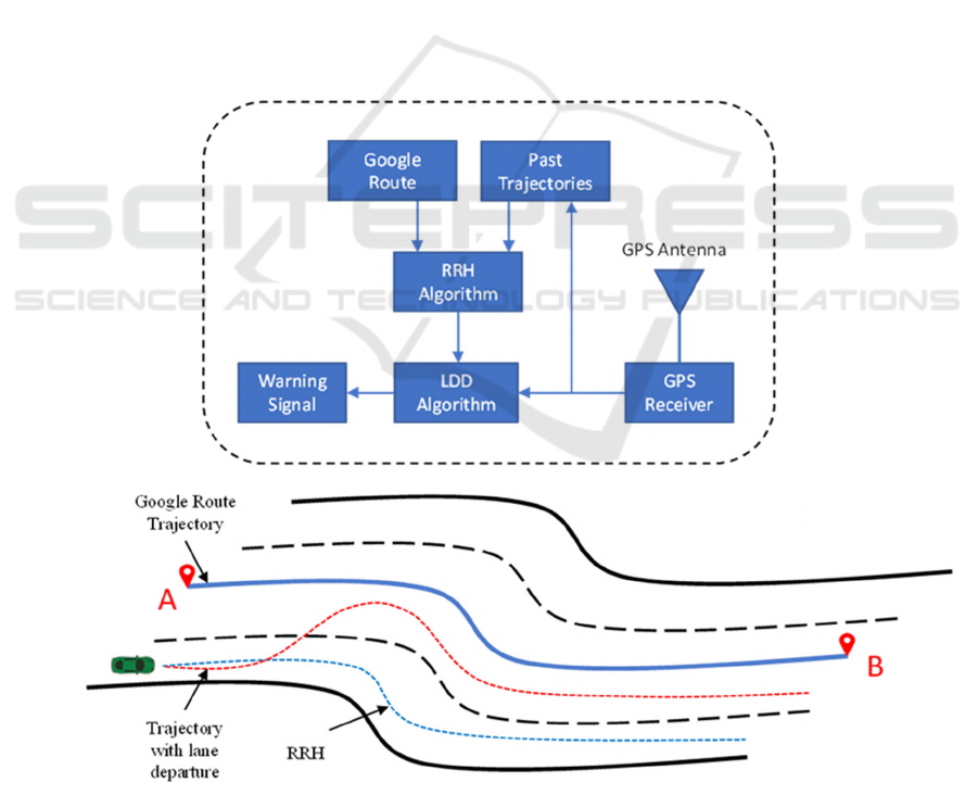
and Google routes as shown in Figure 1a. The
enhanced LDWS can either generate RRH using past
trajectories or from Google routes obtained from
Real-Time Lane Departure Detection Using Google Routes
239
Google Maps. In the updated LDWS, we have
incorporated necessary modifications and
enhancements of the RRH generation algorithm to
accommodate RRH generation from Google routes.
With this additional feature of extracting RRH, our
LDWS is capable of detecting lane departures of a
vehicle in real-time on any road, regardless of
whether the vehicle has traveled on that road in the
past. Our LDWS compares the vehicle trajectory in
real-time with the RRH of that road to detect a lane
departure using our LDD algorithm as depicted in
Figure 1b where a vehicle trajectory with a lane
departure (red dotted line) can be compared with the
RRH (blue dotted line) obtained from the Google
route (blue solid line) or from one of the past
trajectories (not shown in Figure 1b) to determine
lane departure using our LDD algorithm (Faizan et
al., 2019).
We have also made enhancements to our LDD
algorithm to detect lane departure more efficiently.
However, this paper is more focused on the details of
the new feature of extracting RRH from Google
routes obtained from Google Maps. To evaluate the
effectiveness of lane departure detection using RRH
from Google routes, we have compared the results of
lane departure detection using RRH from both
Google routes and past trajectories, which will be
described in more detail in the field tests and results
section.
3 RRH GENERATION FROM
GOOGLE ROUTE
We have developed a backend browser-based
application where we can specify the start and end
points of the desired route on a Google map to obtain
the RRH from the Google route on almost any road
within the US. The user specifies the start and end
location points in the Google map to define the
Google route necessary for RRH generation. Our
backend browser application accesses Google Maps’
API for turn-by-turn directions between the start and
Figure 1: (a) Architecture of the LDWS system. (b) Conceptual diagram demonstrating that RRH (blue dotted line) can be
generated from a Google route (blue solid line, where points A and B are the start and end points, respectively) to detect an
intentional lane change from right to left (red dotted line). The road illustrated in this figure is a 4-lane road with the Google
route shown in the middle.
(1b)
(1a)
VEHITS 2024 - 10th International Conference on Vehicle Technology and Intelligent Transport Systems
240
end points of the route and returns an array of
locations with latitudes and longitudes. In this array
of locations provided by Google Maps, there are more
location points on a curve segment of the road as
compared to a straight segment of the road. This array
of latitudes and longitudes represents the Google
route from which RRH is generated.
We preprocess the array of location points to
obtain a uniform distance resolution before applying
our RRH generation algorithm. To obtain a uniform
distance resolution, we have to access Google Maps
API a few times between intermediate location points
in the array until we get the desired resolution so that
every two consecutive points in the Google Maps
array of locations have the same distance as the
desired resolution typically in 1 to 3 m range. We
have to do more iterations on straight sections in the
array as compared to a curve section because there are
fewer number of points on a straight section as
compared to a curve section.
Our developed RRH generation algorithm
characterizes a typical road segment into straight and
curve sections, as any typical road can have a
combination of straight and curve portions. However,
the roads do not curve abruptly; therefore, the section
between a straight and a curve is characterized as a
transition section by the algorithm. Our algorithm
generates an RRH from the pre-processed Google
route (uniform array of locations) for any given
portion of the road in three major steps.
1) Identification: In the first step, all straight,
curve and transition sections are identified on that
road.
2) Characterization: After identification, each
section is characterized with a set of optimized
parameters that determines the RRH value at any
given point on that road. Every straight section is
characterized by a Path Average Heading (PAH), as
the heading remains constant for the entire length of
a straight section. Since the heading of a curve section
varies uniformly with distance, it is characterized by
a Path Average Heading Slope (PAHS) and an initial
heading (IH), where IH is the heading at the
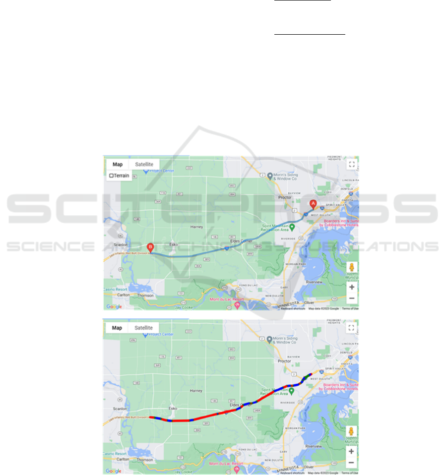
Figure 2: (a) Browser application user interface showing the user-specified route on the Google map to initiate RRH
generation from the Google route. Points A and B indicate the start and end location of the desired route, respectively. (b)
Google route superimposed on the generated RRH with straight, curve and transition sections indicated by red, blue, and
green colors along the route.
(2a)
(2b)
Real-Time Lane Departure Detection Using Google Routes
241

beginning point of the curve section. Each transition
section is characterized the same way as a curve
section.
3) Aggregation: Finally, all the individual
road sections are combined to obtain a composite
RRH for that road to be used with the LDD algorithm
for lane departure detection.
The process of generating RRH from the Google
route using the browser application is illustrated in
Figure 2. Our browser application lets the user specify
the start and end points on a given road on Google
Maps, as shown in Figure 2a, where points A and B
are the start and end points, respectively. After the
user specifies the start and end points, our browser
application runs our RRH generation algorithm and
converts the Google route to RRH consisting of all
sections of the road, as shown in Figure 2b, where the
red, blue, and green colors along the Google route
indicate straight, curve and transition sections,
respectively. Our browser application also generates
a corresponding datafile containing all the relevant
information of all the sections of RRH within the
Google route. The information in this datafile
contains the start and end points of each section
(straight, curve and transition) and the relevant
parameter values characterizing each section to
determine the RRH value for any point on the road.
Using this information, an RRH value can be
calculated on any given point of the road between the
start and end points specified by the user.
3.1 Algorithm and Parameter
Optimization
The implementation steps of our RRH generation
algorithm are as follows:
1) First, the Google route is obtained from the
browser application containing the array of
points in terms of longitude and latitude for
each point. The Google route is then pre-
processed for uniform distance resolution so
that each of the two consecutive points has a
constant distance between them (1-3 m
range), as explained earlier.
2) Then, the heading between two consecutive
points is calculated from the longitude and
latitude of those points (Shahnewaz
Chowdhury & Hayee, 2021). The heading
array is then filtered with a lowpass filter
having a corner frequency of 20 Hz
(cycles/m) and a total stop frequency of 125
Hz (cycles/m). The filtering is done to
smoothen the heading array obtained from
Google Maps. The choice of corner and stop
frequencies is made to ensure the removal of
undesired ripple effects from the heading
array.
3) Next, differential headings per meter are
calculated from the filtered heading array.
The differential heading is then smoothened
to further minimize undesired ripples. The
smoothening is obtained by averaging
differential heading at each point over 40
meters, i.e., ± 20m on either side of the given
point.
4) The average differential heading array is
then used to identify the straight sections
using a threshold of 0.002 deg/m, i.e., any
consecutive portion with a differential
heading of less than the threshold of 0.002
deg/m will be considered a straight section
(Shahnewaz Chowdhury & Hayee, 2021).
This step will generate the start and end
points of each of the straight sections present
in the Google route. Please note that we
combined two consecutive straight sections
that are not too far apart from each other
because a road cannot curve abruptly. For
that purpose, we are using a range of 75-100
m as a parameter to combine two
consecutive straight sections. Straight
sections are then characterized by
calculating a PAH between the start and end
points of each straight section.
5) After identifying and characterizing straight
sections, curve sections are identified and
characterized. For this purpose, any portions
of the Google route between two
consecutive straight sections are considered
curve sections, i.e., any contiguous portions
on the Google route having a differential
heading above the average differential
heading threshold of 0.002 deg/m. A PAHS
value for each of the curve sections between
two consecutive straight sections is then
calculated from the average differential
heading. The beginning and end points of
each of the curve sections are identified
where the average differential heading is
closest to the calculated PAHS on that curve
section. The heading at the beginning point
of each curve section becomes the IH for that
curve section.
6) The above method of identifying the start
and end points of the curve section tends to
make the transition sections longer for those
curves which have a higher value of PAHS.
Therefore, for such curves which have a
VEHITS 2024 - 10th International Conference on Vehicle Technology and Intelligent Transport Systems
242
PAHS value of >0.02 deg/m, we apply
selective thresholding to reduce the lengths
of the transition sections and increase the
lengths of the adjacent straight sections
while keeping the curve section length the
same. To achieve this, we increase the
threshold of 0.002 deg/m (as in step 4) to
0.01 deg/m (5 times the original threshold)
only for those curves which have a PAHS
value of >0.02 deg/m.
7) Similarly, some of the curves with a small
PAHS may be falsely accounted for as curve
sections because their PAHS value is only
slightly higher than the threshold (0.002
deg/m) to be identified as curve sections to
begin with. To identify and eliminate such
false curve sections, the PAHS value for
each of the curve sections is recalculated by
dividing the difference of the PAH of the
two surrounding straight sections by the
distance between them. If such a revised
PAHS turns out to be smaller than 0.002
deg/m (original threshold), then that curve is
absorbed in the surrounding straight
sections.
8) The characterized parameters for each
straight and curve section are then optimized
to minimize the differential heading error
(Shahnewaz Chowdhury & Hayee, 2021)
between the RRH and Google route heading
over the entire portion of each of the straight
and curve sections.
9) In the end, transition sections are
identified and characterized. Any portion of
the Google route between a curve and a
straight section is marked as a transition
section. The heading at the start point of the
transition section becomes the IH of the
transition section. The PAHS of the
transition section is calculated from the
difference in headings between the start and
end points of the transition section divided
by the distance between them.
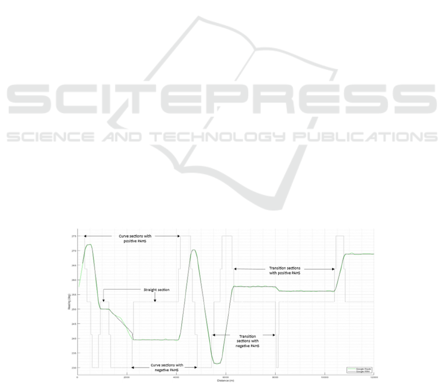
To see the effectiveness of the RRH generated
from the Google route, we have plotted the Google
route heading (green solid line) and the RRH (black
solid line) with respect to distance as shown in Figure
3. To identify straight, curve and transition sections
on the RRH, a mask with a black dotted line is also
shown in Figure 3. The mask has fixed but different
heading values for straight, curve and transition
sections to distinguish them from each other. The
straight sections have a fixed mask value of 252.5
o
(almost in the middle of Figure 3). For each of the
curve and transition sections, two different mask
values are attributed to each curve or transition
section depending on the PAHS. The mask value for
the curve section is either 275
o
or 230
o
, depending on
whether the PAHS is positive or negative,
respectively. Similarly, the mask value for the
transition section is 263.75
o
or 241.25
o
, depending on
whether the PAHS is positive or negative. Please note
that specific mask values are chosen to mark the
difference between the straight, curve and transition
sections within the RRH for the Google route in
Figure 3.
The RRH values (black solid line) match pretty
well with the Google route heading (green),
especially for straight sections (Figure 3). The match
between the RRH and the Google route varies for
curve sections and we noticed that for one of the
sharper curve sections between 1500 m and 2200 m,
the match is not as good as for the other portions
(Figure 3). This can be improved by tweaking the
conditions of the RRH generation algorithm in the
Figure 3: Google route heading (green) and corresponding RRH (solid black) vs. distance. A mask (black dotted line) is drawn
to indicate the straight, curve and transition sections.
Real-Time Lane Departure Detection Using Google Routes
243
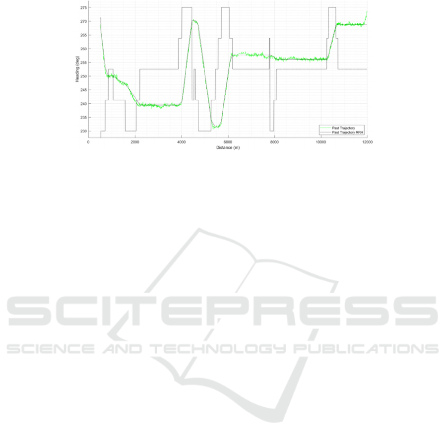
Figure 4: A past trajectory heading (green) and corresponding RRH (solid black) vs. distance. A mask (black dotted line) is
drawn to indicate the straight, curve and transition sections.
future. However, our main goal is that the RRH
values for the straight sections are reliable so that
unintentional lane departure on long stretches of the
straight sections can be successfully detected.
We also wanted to compare the accuracy of the
Google RRH with the RRH obtained from the past
trajectories. Therefore, we applied the modified RRH
generation algorithm to one of the past vehicle
trajectories obtained on the Interstate I-35
southbound which is the same portion of I-35 for
which the Google route was used to extract RRH. The
trajectory length was a little shorter than 12 km
covering almost the same portion as the Google route
in Figure 3. The trajectory heading vs. distance is
plotted in Figure 4. For reference, an RRH obtained
from this trajectory is also shown in Figure 4. The
same mask as in Figure 3 is also used in Figure 4 to
differentiate among straight, curve and transition
sections of the RRH. Figure 4 shows that the
generated RRH (black solid line) follows the vehicle
trajectory heading (green) fairly well, indicating that
the modified RRH generation algorithm also works
well for the past trajectories. In fact, for a much
sharper curve present in the trajectory (between 1500
m and 2200 m range), the match between RRH and
the past trajectory is much better (Figure 4), as
compared to the similar match for the Google route
(Figure 3). These discrepancies in Google RRH exist
because sometimes the road width changes, i.e., the
number of lanes cause abrupt heading deviations in
the Google route. However, a more rigorous
comparison of the RRH obtained from the Google
route and that of the past vehicle trajectory will be
made later by detecting lane departures using our
LDD algorithm.
4 FIELD TEST AND RESULTS
We performed many field tests to evaluate the RRH
obtained from the Google route using our LDD
algorithm. All the field tests were performed by
driving a test vehicle multiple times on the same 12
km segment of Interstate I-35 southbound, for which
an RRH was extracted from the Google route as
discussed earlier. Each of the test runs covered a
portion of the 12 km road segment to ensure that the
test vehicle remained on the same portion of the road
for which an RRH was extracted earlier from the
Google route. The test vehicle was driven at about the
speed limit (70 MPH) on the 4-lane freeway (2 lanes
each way) and many lane changes were made
intentionally during the field tests. For safety reasons,
intentional lane changes were made to test the
accuracy of lane departure detection. The vehicle
trajectory data for each of the test runs were collected
and evaluated with our LDD algorithm to detect the
start and end of the lane changes present in each
trajectory. Four such trajectories (red, blue, purple &
orange colors) from the test runs are shown in Figure
5a, where vehicle heading vs. vehicle traveled
distance is plotted. For reference, Google RRH (black
solid line) is also shown on the same scale in Figure
5a. In the first two trajectories (red and blue) shown
in Figure 5a, a total of 4 lane changes were made, and
in the third trajectory (purple), only 2 lane changes
were made. There was no lane change made for the
fourth trajectory (orange) to ensure that no false alarm
was detected by our LDD algorithm. All lane
changes were made only on the straight portions of
the road as unintentional lane departure is more
relevant on longer stretches of straight portions of the
road as discussed earlier.
VEHITS 2024 - 10th International Conference on Vehicle Technology and Intelligent Transport Systems
244
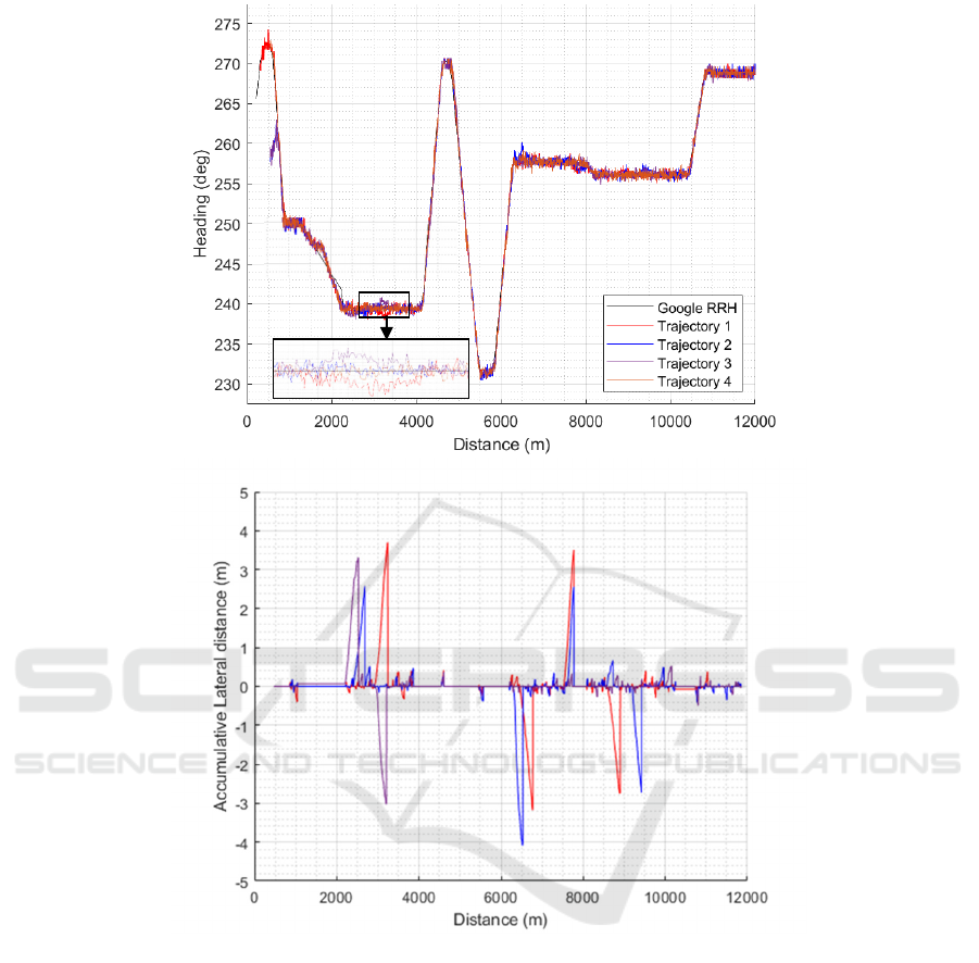
Figure 5: (5a) RRH resulting from the Google route (black) along with the headings of four different trajectories (red, blue,
purple & orange) on the same route vs. distance. A zoomed in portion of the Google RRH and 4 trajectories between the 3000
m to 3500 m distance range is shown as an in-set in the figure. (5b) Vehicle accumulative lateral distance vs. traveled distance
for four different driven trajectories (red, blue, purple & orange). The vehicle accumulative lateral distance is calculated using
Google RRH.
However, from the trajectories shown in Figure
5a, lane changes cannot be visibly identified because
there is a very small difference in the heading of a
vehicle trajectory and the Google RRH. An example
of a lane change is highlighted in a zoomed portion of
Figure 5a between the 3000 m and 3500 m range to
show that there is a lane change in two of the four
trajectories (red and purple) in opposite directions
indicated by the vehicle heading deviation in the
opposite directions as compared to the Google RRH.
Similarly, for the other two trajectories (blue and
orange), there was no lane change for this portion, so
no noticeable deviation was seen in vehicle heading
as compared to the Google RRH.
To evaluate the accuracy of the lane change
timing and duration, the accumulative lateral distance
of the vehicle for each trajectory vs. traveled distance
is shown in Figure 5b. The colors of the accumulated
lateral distance for each trajectory are kept the same
as in Figure 5a. When the accumulative lateral
distance exceeds a certain threshold (~1m) value on
either side, it is considered a lane departure. All lane
Zoomed-in
portion
(5a)
(5b)
Real-Time Lane Departure Detection Using Google Routes
245
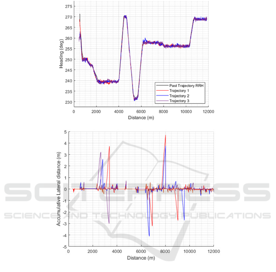
Figure 6: (6a) RRH resulting from one of the past trajectories (black) along with the headings of three different trajectories
(red, blue & purple) vs. distance. (6b) Vehicle accumulative lateral distance vs. traveled distance for three different driven
trajectories (red, blue & purple). The vehicle accumulative lateral distance is calculated using the RRH extracted from a past
trajectory.
changes were accurately identified by our algorithm
indicating that the RRH obtained from Google route
works well for detecting lane departures, either
intentional (lane change) or unintentional. The start
and stop of each of the lane changes are clearly
identifiable in Figure 5b. For the orange trajectory,
where there is no lane change, the accumulative
lateral distance never exceeds the threshold of 1 m.
We also wanted to compare the accuracy of lane
changes being identified correctly when the RRH was
generated from a Google route as well as a past
trajectory. We have used Trajectory 4 (orange) of
Figure 5 to generate an RRH from it because it does
not have any lane changes. The remaining three
trajectories (red, blue & purple) from the test runs
were used to detect lane changes in them using the
RRH extracted from one of the past trajectories
(Trajectory 4). The heading of the three trajectories
(red, blue and purple) are shown again in Figure 6a,
where vehicle heading is plotted with respect to
traveled distance. As stated earlier, in two of these
three trajectories (red and blue), a total of 4 lane
changes were made in each, and in the third trajectory
(purple), only 2 lane changes were made. For
(6a)
(6
b
)
VEHITS 2024 - 10th International Conference on Vehicle Technology and Intelligent Transport Systems
246

reference, RRH extracted from Trajectory 4 has also
been shown in Figure 6a.
To evaluate the accuracy of the lane change
timing and duration, the accumulative lateral distance
of the vehicle for each of the three trajectories using
the RRH from Trajectory 4 is calculated and is shown
in Figure 6b vs. traveled distance. The colors of the
accumulative lateral distance for each trajectory are
kept the same as in Figure 6a. All lane changes were
accurately identified by our algorithm showing the
accuracy of the RRH obtained from a past trajectory
using the modified RRH generation algorithm. The
start and stop of each of the lane changes are clearly
identifiable in Figure 6b. These results indicate that
the lane departure can be accurately detected
irrespective of whether the RRH is generated from a
Google route or a past trajectory for straight portions
of the road.
5 CONCLUSIONS
We have successfully developed and implemented
the algorithm to extract RRH from a Google route to
work with our previously developed LDWS to detect
unintentional lane departures. We have evaluated the
effectiveness of the RRH from the Google route by
performing field tests and comparing the results with
that of the RRH from a past trajectory. Our results
indicate that our LDWS can accurately detect a lane
departure irrespective of whether the RRH is
generated from a Google route or a past trajectory for
straight portions of the road. However, to ensure
accurate lane departure detection on curved road
sections, further refinement of the RRH generation
algorithm is necessary to align the RRH with the
trajectory. Although results have been reported from
fourtrips of many along the same 12 km segment of
the Interstate I-35 southbound route, it is worth
mentioning that this is an ongoing work, and we are
in the process of validating this approach with more
data from different routes.
ACKNOWLEDGEMENTS
The authors wish to acknowledge those who made
this research possible. This work was made possible
by Minnesota cities and counties by the Local Road
Research Board with support from MnDOT’s Office
of Research & Innovation.
REFERENCES
An, X., Wu, M., & He, H. (2006). A novel approach to
provide lane departure warning using only one forward-
looking camera. International Symposium on
Collaborative Technologies and Systems (CTS’06),
356–362.
Antony, M. M., & Whenish, R. (2021). Advanced driver
assistance systems (ADAS). In Automotive Embedded
Systems: Key Technologies, Innovations, and
Applications (pp. 165–181). Springer
Baili, J., Marzougui, M., Sboui, A., Lahouar, S., Hergli, M.,
Bose, J. S. C., & Besbes, K. (2017). Lane departure
detection using image processing techniques. 2017 2nd
International Conference on Anti-Cyber Crimes
(ICACC), 238–241.
Bajikar, S., Gorjestani, A., Simpkins, P., & Donath, M.
(1997). Evaluation of in-vehicle GPS-based lane
position sensing for preventing road departure.
Proceedings of Conference on Intelligent
Transportation Systems, 397–402.
Chen, W., Wang, W., Wang, K., Li, Z., Li, H., & Liu, S.
(2020). Lane departure warning systems and lane line
detection methods based on image processing and
semantic segmentation: A review. Journal of Traffic
and Transportation Engineering (English Edition),
7(6), 748–774.
Chen, Y., & Boukerche, A. (2020). A novel lane departure
warning system for improving road safety. ICC 2020-
2020 IEEE International Conference on
Communications (ICC), 1–6.
Clanton, J. M., Bevly, D. M., & Hodel, A. S. (2009). A low-
cost solution for an integrated multisensor lane
departure warning system. IEEE Transactions on
Intelligent Transportation Systems, 10(1), 47–59.
Dobler, G., Rothe, S., Betzitza, P., & Hartlieb, M. (2000).
Vehicle with optical scanning device for a lateral road
area. Google Patents.
Faizan, M., Hussain, S., & Hayee, M. I. (2019). Design and
development of in-vehicle lane departure warning
system using standard global positioning system
receiver. Transportation Research Record, 2673(8),
648–656.
Gamal, I., Badawy, A., Al-Habal, A. M., Adawy, M. E.,
Khalil, K. K., El-Moursy, M. A., & Khattab, A. (2019).
A robust, real-time and calibration-free lane departure
warning system. Microprocessors and Microsystems,
71, 102874.
Hsiao, P.-Y., & Yeh, C.-W. (2006). A portable real-time
lane departure warning system based on embedded
calculating technique. 2006 IEEE 63rd Vehicular
Technology Conference, 6, 2982–2986.
Jung, H., Min, J., & Kim, J. (2013). An efficient lane
detection algorithm for lane departure detection. 2013
IEEE Intelligent Vehicles Symposium (IV), 976–981.
Leng, Y.-C., & Chen, C.-L. (2010). Vision-based lane
departure detection system in urban traffic scenes. 2010
11th International Conference on Control Automation
Robotics & Vision, 1875–1880.
Real-Time Lane Departure Detection Using Google Routes
247

Lindner, P., Richter, E., Wanielik, G., Takagi, K., & Isogai,
A. (2009). Multi-channel lidar processing for lane
detection and estimation. 2009 12th International IEEE
Conference on Intelligent Transportation Systems, 1–6.
McCall, J. C., & Trivedi, M. M. (2006). Video-based lane
estimation and tracking for driver assistance: Survey,
system, and evaluation. IEEE Transactions on
Intelligent Transportation Systems, 7(1), 20–37.
Road traffic injuries. (n.d.). Retrieved December 11, 2023,
from https://www.who.int/news-room/fact-sheets/deta
il/road-traffic-injuries
Rose, C., Britt, J., Allen, J., & Bevly, D. (2014). An
integrated vehicle navigation system utilizing lane-
detection and lateral position estimation systems in
difficult environments for GPS. IEEE Transactions on
Intelligent Transportation Systems, 15(6), 2615–2629.
Sang, I. C., & Norris, W. R. (2024). A Robust Lane
Detection Algorithm Adaptable to Challenging
Weather Conditions. IEEE Access.
Shahnewaz Chowdhury, M. T. H., & Hayee, M. I. (2021).
Generation of Road Reference Heading using GPS
Trajectories for Accurate Lane Departure Detection.
Singh, S. (2015). Critical reasons for crashes investigated
in the national motor vehicle crash causation survey.
Son, J., Yoo, H., Kim, S., & Sohn, K. (2015). Real-time
illumination invariant lane detection for lane departure
warning system. Expert Systems with Applications,
42(4), 1816-1824.
Sternlund, S., Strandroth, J., Rizzi, M., Lie, A., & Tingvall,
C. (2017). The effectiveness of lane departure warning
systems—A reduction in real-world passenger car
injury crashes. Traffic Injury Prevention, 18(2), 225–
229.
Toledo-Moreo, R., & Zamora-Izquierdo, M. A. (2009).
IMM-based lane-change prediction in highways with
low-cost GPS/INS. IEEE Transactions on Intelligent
Transportation Systems, 10(1), 180–185.
Weon, I. S., Lee. S.G. & Woo, S. H. (2021). Lane Departure
Detecting with Classification of Roadway Based on
Bezier Curve Fitting Using DGPS/GIS. Tehnički
vjesnik, 28(1), 248-255.
Yu, B., Zhang, W., & Cai, Y. (2008). A lane departure
warning system based on machine vision. 2008 IEEE
Pacific-Asia Workshop on Computational Intelligence
and Industrial Application, 1, 197–201.
VEHITS 2024 - 10th International Conference on Vehicle Technology and Intelligent Transport Systems
248
