Behind the Lens: Exploring UV Reflection
J. Fonseca
a
, P. Teixeira
b
and L. Ventura
c
University of São Paulo, Department of Eletrical and Computer Engineering, Brazil
Keywords: Sunglasses, UV Protection, Internal Reflection, Eye Damage, ISO 12312-1.
Abstract: Current UV protection regulations mainly center on sunglass lenses' light passage, using quantitative criteria
based on sunglass categories. Yet, studies, including this one, stress the necessity to enhance and adjust these
norms. Our findings underscore aligning standards, notably the Brazilian ISO NBR 12312-1, with ICNIRP
guidelines. Environmental radiation dispersion where sunglasses are worn can impact eye safety despite dark
lenses, potentially harming protection due to pupil dilation. This project marks a pivotal step in UV protection
analysis, crafting a methodology to measure light entering the eyes as UV rays penetrate sunglass lenses. We
devised an apparatus with LEDs, sensors, and a mannequin to gauge eye-reaching radiation. Preliminary
results reveal 10 to 15% of this wavelength's light penetrates the eyes, varying based on lens characteristics
like material and curvature. However, these initial tests only validated the system with red LEDs, limiting
their scope. Validating this research urges adapting existing norms to assess UV radiation reaching the eyes
and establish effective protection methods.
1 INTRODUCTION
Exposure to ultraviolet (UV) solar radiation poses a
significant threat to human health and well-being,
particularly concerning ocular health. The use of
sunglasses is of paramount importance as the primary
protective measure against this radiation, especially
in regions such as Brazil, characterized by high levels
of UV radiation
(VENTURA et al, 2022).
However, the
effectiveness of conventional dark lenses in
safeguarding against UV radiation warrants careful
examination.
These lenses, lacking adequate UV protection,
may hinder the natural movement of the pupil,
resulting in increased UV exposure and potentially
intensifying adverse ocular consequences. While
existing regulations, such as ISO 12312-
1:2022
(ABNT, 2014)
, are crucial for overseeing
sunglass standards and ensuring ocular safety, they
currently overlook a crucial aspect: the interaction of
UV rays reflected within the lenses and their impact
on ocular health.
This oversight becomes particularly pertinent
when contrasted with criteria established by the
a
https://orcid.org/0000-0001-9927-6274
b
https://orcid.org/0009-0007-4233-6716
c
https://orcid.org/0000-0002-5292-6687
International Commission on Non-Ionizing Radiation
Protection (ICNIRP)
(ICNIRP, 2004)
, which delineates
limits for UV radiation exposure. The ISO
standardizes sunglass UV protection solely in terms
of lens 'darkening'
(DIFFEY, 2002)
, neglecting the
incorporation of structural geometry in ocular safety
considerations and failing to encompass the impact of
UV radiation diffused in the environment, which can
potentially harm the eyes. Consequently, these
disparities underscore the need for a broader scope of
considerations within sunglass standards to ensure
comprehensive ocular protection (MASILI, 2015).
The primary focus of this study was to develop a
prototype that quantifies the incident UV radiation
reaching the eyes due to the internal reflection of the
lenses.
2 STATE-OF-THE-ART
Human visual perception is a complex interplay
between light and the visual system. As light enters
the human eye, it undergoes a series of processes that
culminate in the formation of a conscious visual
Fonseca, J., Teixeira, P. and Ventura, L.
Behind the Lens: Exploring UV Reflection.
DOI: 10.5220/0012575500003657
Paper published under CC license (CC BY-NC-ND 4.0)
In Proceedings of the 17th International Joint Conference on Biomedical Engineering Systems and Technologies (BIOSTEC 2024) - Volume 1, pages 191-194
ISBN: 978-989-758-688-0; ISSN: 2184-4305
Proceedings Copyright © 2024 by SCITEPRESS – Science and Technology Publications, Lda.
191
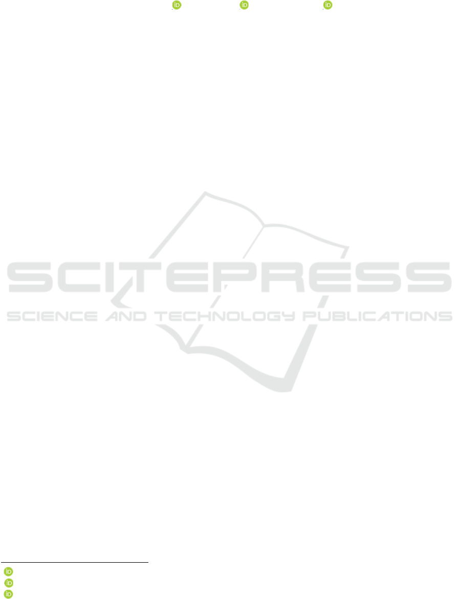
impression. However, light represents just a portion
of the electromagnetic spectrum, typically associated
with visible light. Figure 01 depicts the
electromagnetic spectrum, housing Ultraviolet
Radiation (UV), the focus of this study, transmitted
by the sun. The incidence of this radiation until it
reaches the atmosphere undergoes several
phenomena, including reflection and backscattering.
Reflection is the primary physical phenomenon
enabling human visual perception
(HALLIDAY, 2012).
Figure 1: Electromagnetic Spectrum.
2.1 Albedo
Albedo, in essence, denotes the reflective property of
surfaces and materials, directly impacting how they
interact with incoming radiation. Its responsiveness
varies according to the wavelength of radiation,
implying that different wavelengths of light provoke
distinct levels of reflection from surfaces.
Specifically concerning ultraviolet (UV) radiation,
materials exhibit diverse albedo values, signifying
their capacity to reflect UV light
(MISILI, 2018).
Here are some examples of common materials and
their respective albedos in relation to UV radiation:
• Fresh snow: 80-90%
• Sand: 20-30%
• Concrete: 15-25%
• Grass: 5-10%
• Asphalt: 5-10%
• Clean water: 3-10%
These values may fluctuate based on specific
conditions such as surface texture, impurities, and
other influencing factors.
2.2 Standards and Regulations
The international standard ISO 12312-1, alongside
itsBrazilian translation, the NBR ISO 12312-1,
recognizesultraviolet radiation (UV) as composed of
three distinct subregions within the electromagnetic
spectrum: UV-A (320–400 nm), UV-B (280–320
nm),and UV-C (100–280 nm).
[7]
In the context of
protection against ultravioletradiation (UV),
addressing normative discrepancies betweenthe
international standard ISO 12312-1 and its
nationalcounterparts, such as ISO NBR 12312-1 in
Brazil, incomparison to guidelines established by the
InternationalCommission on Non-Ionizing Radiation
Protection (ICNIRP), is essential. One of the main
discrepancies lies in the definitionof the wavelength
range of UV radiation
(ICNIRP, 2004).
This division is
essential to understanding the effects of UV radiation
on objects and organisms, including humans.
3 MATERIALS AND METHODS
The following methodology outlines the development
of a prototype aimed at measuring the contribution of
internal reflection of UV radiation occurring within
the lenses of sunglasses and reaching the eyes. To
obtain this measurement, several parameters and
components need standardization for increased result
accuracy.
In this study, the primary focus will be measuring
the intensity of ultraviolet radiation that occurs
through reflections from sunglass lenses and reaches
the eyes, specifically targeting UV radiation in the
range of 380 – 400 nm. The system setup primarily
involves the utilization of emitting sources and
detectors within this spectral range.
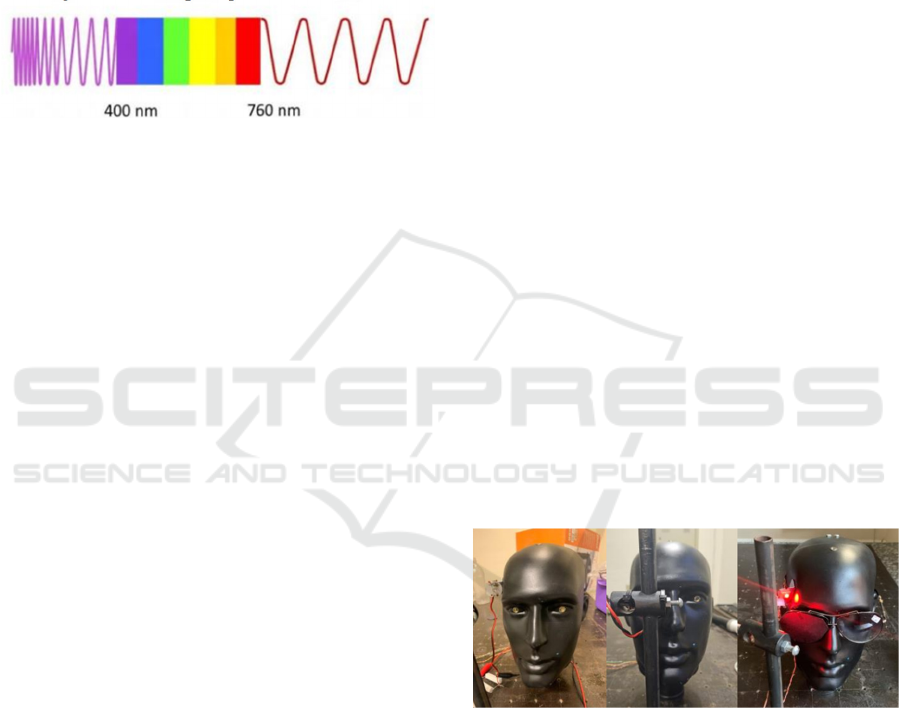
To validate the proposed issue and identify if there
is a reflection coming from the sunglasses lenses, a
preliminary system was assembled using red LEDs in
the 640 nm range and visible sensors to collect light
values reaching the eyes originating from their
reflection. The developed configuration is illustrated
in Figure 02 below.
Figure 2: Proposed Experimental Setup.
3.1 Data Acquisition
Practically, the aim is to calculate and measure the
amount of radiation reaching the eyes from
reflections acquired withs sunglasses. To identify this
reflection parameter as a percentage, determining the
maximum experimental measurement without the
glasses and identifying all influencing parameters are
crucial for obtaining accurate results. The initial
methodology adopted is as follows:
BIODEVICES 2024 - 17th International Conference on Biomedical Electronics and Devices
192

• Nominal Measure 100% (NM100)
To establish the nominal 100% system, direct
solar radiation incidence needs to be obtained without
sunglass interference. Experimentally, two sensors
(OPT101 model) representing the mannequin's eyes
and two fixed red LEDs are used—one simulating
total reflection (LED1) and the other imitating
reflections from albedos and surfaces (LED2).
The three contributing factors to the collected result
involve:
o Direct Incidence (DI): Radiation
directly incident on the sensor, from
LED1.
o LED1 Noise (N1): Contributing
radiation from above and laterally due
to LED1's opening, adding to the result.
o LED2 Noise (N2): Radiation reflected
by ambient surfaces reaching the
sensor, from LED2.
Mathematically:
𝑁𝑀100 = 𝐷𝐼 + 𝑁1 + 𝑁2
• Measure with Sunglasses (MWS)
Adding sunglasses to the equation introduces new
parameters. Experimentally, sunglasses with the lens
covered on the external side were used to maintain
transmittance, and LED2 was activated (Figure 18).
Results collected are contributions from:
o LED2 Noise (N2): Ambient-reflected
radiation reaching the sensor.
o Radiation Reflected by the Lens (RL):
The main value of interest in this study,
representing UV radiation reaching the
eyes due to sunglasses.
Mathematically:
𝑀𝑊𝑆 = 𝑁2 + 𝑅𝐿
To isolate ambient radiation values (AR) from
MD100 and MWS, a measure was taken to establish
a 0% baseline for this system.
• Measure of LED2 0% (ML2_0)
To determine only the fraction of radiation
reflected by the environment (AR), only LED2 was
turned on without the glasses, and the calculated
baseline value was observed.
To calculate the contribution of lens reflection to
the total percentage of solar incidence in nominal
conditions, the following steps are taken:
First, calculate only the lens reflection contribution
inside:
𝑅𝐿 = 𝑀𝑊𝑆 − 𝑁2
Then, eliminate noise values from NM100:
𝐷𝐼 = 𝑁𝑀100 − 𝑁1 − 𝑁2
Finally, to obtain the desired parameter as a
percentage:
𝐿𝑒𝑛𝑠 𝑅𝑒𝑓𝑙𝑒𝑐𝑡𝑖𝑜𝑛 % = 𝑅𝐿 / 𝐷𝐼
3.2 Electronic Components
To achieve the proposed data acquisition, the system
requires suitable and efficient components. The
activation of the project's main components involved
the following elements and connections:
1. Red LEDs (640 nm): Light-emitting diodes
that emit red light at a wavelength of 760
nanometers.
2. High-Power Resistor (10W): A resistor
designed to handle high power, in this case,
rated for 10 watts of power dissipation.
3. OPT101 Sensor: An analog photodiode sensor
used for precision light measurement,
converting light intensity into an electrical
signal.
4. Conversion Board with LM358: A board
utilizing the LM358 operational amplifier for
signal amplification or conditioning, often
used in sensor interfaces.
5. Low Pass Filter: An electronic filter that
allows low frequency signals to pass through
while attenuating higher frequencies, often
used to eliminate noise or unwanted high-
frequency components.
6. Resistive Divider: A circuit consisting of
resistors used to create a fraction of an input
voltage, commonly employed for voltage
scaling or level shifting.
7. ADS115 Analog-to-Digital Converter: An
ADC (Analog-to-Digital Converter) used to
convert analog signals (like voltage) into
digital data for processing by a
microcontroller or computer.
8. Arduino NANO: A small, versatile
microcontroller board based on the
ATmega328P chip, commonly used in various
electronic projects for control and data
acquisition.
9. Micro SD Card Adapter: An adapter allowing
a micro-SD card to be used with devices
designed for standard SD cards, enabling
storage or data logging capabilities.
These components were utilized and
interconnected to facilitate the functioning and data
acquisition process as part of the project's electronic
setup. The diagram in Figure 03 shows this
connection.
Behind the Lens: Exploring UV Reflection
193
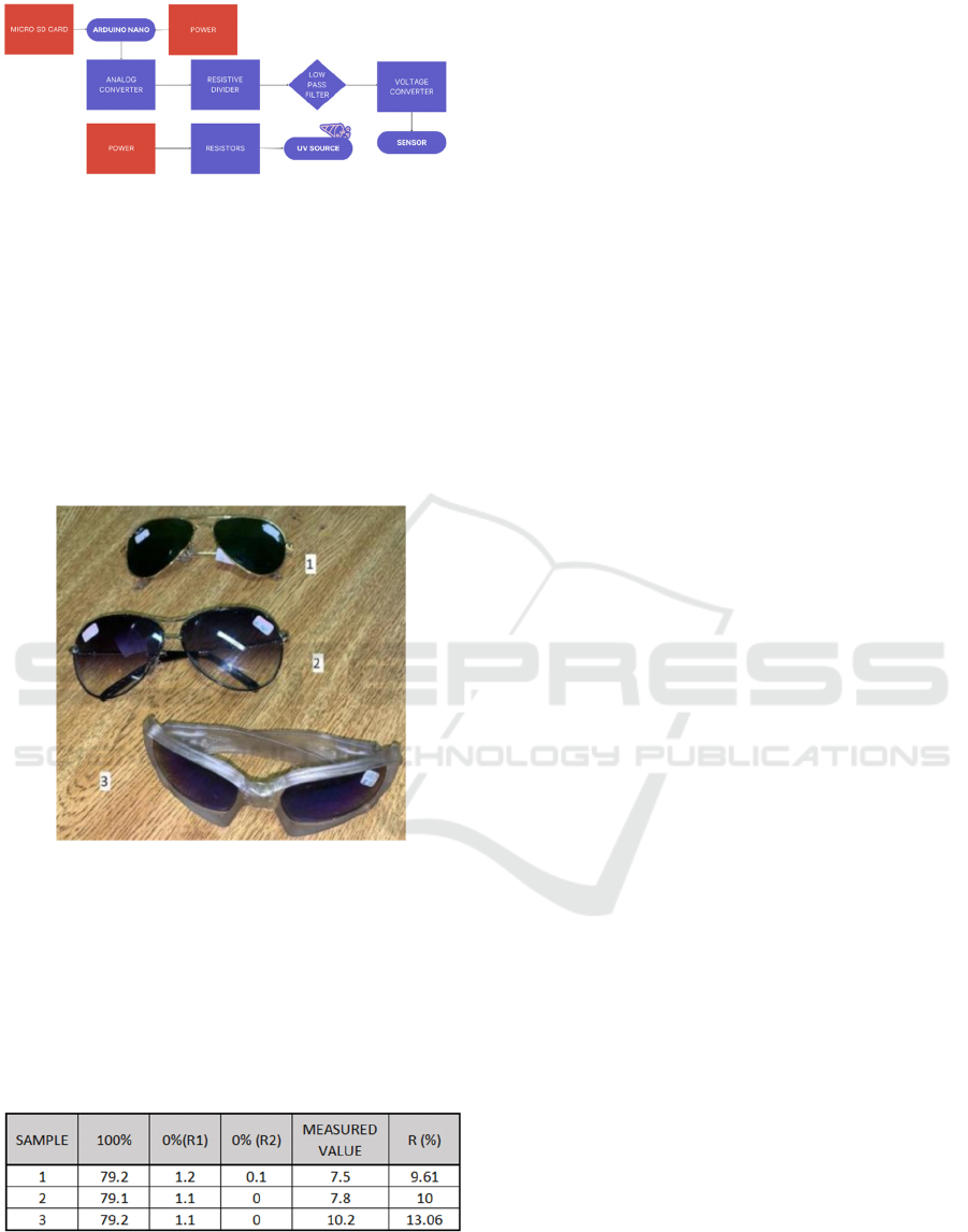
Figure 3: Electronic system diagram.
4 RESULTS
The experiment utilized three different sunglass
samples, depicted in Figure 04. Two of these samples
(Sample 1 and 2) shared similar physical and visual
characteristics, a similarity reflected in the obtained
data respectively. The samples were identified as
follows: 1 – n°9, Lot 23; 2 – n°50, Lot 13; 3 – n°22,
Lot 23.
Figure 4: Samples used for testing.
Implementing the proposed methodology for data
treatment, collecting values at 100% and 0%, yielded
the following results presented in Table 01, based on
the samples from Figure 04, with 10 test runs
conducted. The standard LED power supply
for all tests remained at 10V.
Table 1: Preliminary results of reflection.
Table 01 provides preliminary results using
illumination and detection in the red spectral region.
These findings indicate the feasibility of the
experimental setup, here employing an LED with a
peak wavelength of 640 nm. It's noteworthy that the
final prototype aims to operate in the ultraviolet
region, around 390 nm, and is currently under
development at the Ophthalmic Instrumentation
Laboratory at USP São Carlos.
5 CONCLUSIONS
The study highlights the need for a significantly high-
intensity LED source, presenting challenges in
achieving a saturated 100% signal, particularly
affecting commonly used sensors. The validation
emphasizes the reflection of UV radiation in sunglass
lenses, despite being at low levels, which may
interfere with long-term vision. This work represents
an ongoing refinement process to quantify UV
radiation reaching the eyes, requiring the acquisition
and testing of robust components. There is a
substantial need for this study and adaptations in
standards to address these considerations. Future
work aims to develop a more complex prototype for
measuring the quality of lenses regarding UV
reflection, validating the research's importance by
revealing significant reflection indices.
REFERENCES
Ventura, L.; et al Ocular Bioengineering – Sunglasses and
their standards. Ponta Grossa – PR: Atena, 2022 p135.
Halliday, David; Resnick, Robert; Walker, Jearl. Princípios
de Física. 9ed. Rio de Janeiro: LTC, 2012. V.1.
Diffey, Bl. Sources and measurement of ultravioleta
radiation. Metrods. 2002;28(1);4-13.
Masili, M.; Shciabel, H.; Ventura, L. Contribuition to the
adiation protection for sunglasses standards. Radiation
Protection Dosimetry. V.164, p435, 2015.
ICNIRP, Internal Commision on Non-Ionizing Radiation
Protection. Guidelines on limits of exposure to
ultravioleta radiation of wavelenghts between 180nm
and 400nm (incoherent optical radiation). Health
Physics, ago. 2004.
Masili, M. Duarte, F.O., Ventura, L. Blue-light
transmittance in sunglasses over long-term irradiation
within a solar simulator. Res. Biomed. Eng. 2018.
ABNT NBR ISSO 12312-1: Sunglasses and related
products – Safety requirements and test methods. Rio
de Janeiro: ABNT, 2014.
BIODEVICES 2024 - 17th International Conference on Biomedical Electronics and Devices
194
