
Applications Model: A High-Level Design Model
for Rich Web-Based Applications
Nalaka R. Dissanayake
a
and Alexander Bolotov
b
School of Computer Science and Engineering, University of Westminster, 115 New Cavendish Street, London, U.K.
Keywords: Design Model, High-Level, Platforms, Rich Web-Based Applications, Software Architecture, Tiers.
Abstract: Rich web-based applications are complex systems with multiple application elements running on diverse
platforms distributed over different tiers. There are no UML-based modelling languages or tools catering for
the specificity of the rich web-based applications to model the high-level aspects of application elements,
platforms, and tiers. This paper proposes a model named the Applications model and its modelling elements
to design the high-level application elements of rich web-based applications, the platforms they execute, and
the tiers they belong to. The proposed model and the modelling elements improve the simplicity and
readability of the high-level design of rich web-based applications. Our ongoing research expects to introduce
more UML-based models and modelling elements to assist in designing all the aspects of rich web-based
applications aligning with the Rich Web-based Applications Architectural style and then provide UML
profiles to produce a formal UML extension.
1 INTRODUCTION
This section first provides the background details to
understand the context of this paper and then states
the problem within the context and the motivation for
the writing. After that, the paper’s aim and objectives
are specified; next, the research methodology is
discussed. Finally, the article’s structure is given to
understand the flow of the rest of the document.
1.1 Background
This section briefly discusses the main concepts
related to the research problem, setting the paper’s
context.
1.1.1 Software Modelling
Software modelling involves designing and
documenting different aspects of software systems,
such as requirements, architecture, algorithms, and
databases (The Institute of Electrical and Electronics
Engineers, 2002). The design process comprises two
phases.
a
https://orcid.org/0000-0002-4616-5658
b
https://orcid.org/0000-0001-9966-7558
High-level/ Preliminary Design (architectural
design) is the process of identifying the high-level
elements in the system and their relationships. (The
Institute of Electrical and Electronics Engineers,
2002).
Low-level/ Detailed Design is “the process of
refining and expanding the preliminary design of a
system or component to the extent that the design is
sufficiently complete to be implemented” (The
Institute of Electrical and Electronics Engineers,
2002).
The Unified Modelling Language (UML) (OMG,
2023) is a widely accepted generic tool for designing
software systems (Fuentes & Vallecillo, 2004).
1.1.2 Software Architecture
Software architectural design provides an overall
abstract picture of the elements and their relationships
within a system at its run time, assisting in realising
the system (Fielding, 2000). Architecture is the
foundation of any software system, and the support
gained from a carefully designed and sound
architecture is significant at all phases of software
engineering projects (Solutions, 2014). The increased
Dissanayake, N. and Bolotov, A.
Applications Model: A High-Level Design Model for Rich Web-Based Applications.
DOI: 10.5220/0012605600003687
Paper published under CC license (CC BY-NC-ND 4.0)
In Proceedings of the 19th International Conference on Evaluation of Novel Approaches to Software Engineering (ENASE 2024), pages 319-327
ISBN: 978-989-758-696-5; ISSN: 2184-4895
Proceedings Copyright © 2024 by SCITEPRESS – Science and Technology Publications, Lda.
319

realisation of the system helps reduce complexity
(Hough, 1993) since software complexity encloses
the difficulties in understanding (Zuse, 1992).
Formal architectural description languages
(ADLs) are available to design software architectures
(Ozkaya & Kloukinas, 2013); however, UML-based
semi-formal architectural designing languages/tools
are more usable and admired over formal ADLs
because of their graphical syntax. Our ongoing
research focuses on UML-based modelling aspects
for RiWAs.
1.1.3 Rich Web-Based Applications
We have extended the traditional term Rich Internet
Applications (RIAs) into Rich web-based
applications (RiWAs) (Dissanayake & Dias, 2018)
during the early stage of our research. RiWAs denote
a wide range of systems – which offer a higher user
experience compared to traditional web applications
– combining their advanced rich Graphical User
Interfaces (GUIs) with faster Delta-Communication
(DC) (Dissanayake & Dias, 2017) technologies.
Commonly used apps, such as Facebook, Google
apps, and Microsoft apps, are RiWAs.
RiWAs development tools like libraries,
frameworks, IDEs, dependency management and
build tools have immensely evolved over the last two
decades to cater for the specificity of the RiWAs
(Dissanayake & Dias, 2018) by assisting in
developing the rich GUIs, DC, and related
components. However, other RiWAs engineering
concepts – like architectural styles, design patterns,
design, and testing methods – and tools for them have
not advanced much (Dissanayake & Dias, 2016).
The RiWAs are complex systems with multiple
application elements running on diverse platforms
distributed over different tiers (see Section 3.1). The
client application elements of the RiWAs can be
browser-based apps, mobile apps, or even desktop
apps or Internet of Things (IoT) devices, and the
server application elements can be web services and
processes (see Section 3.1.1). RiWAs engineering
would benefit from modelling concepts/tools like
styles, patterns, and methods to realise the system’s
abstract formalism, design them, and share the
knowledge and experience gained from past projects
(Dissanayake & Dias, 2016).
1.2 Problem and Motivation
Our ongoing research intends to address the absence
of a domain-specific modelling language to cater for
the complexity and specificity of the RiWAs
mentioned in the previous section. While studying the
solutions available to bridge this gap, it was noted that
none of them proposes notations to model the high-
level tiers and application elements that can simplify
the design (see Section 2). Also, modelling details of
RiWAs’ platforms using the UML metamodel’s node
notation makes the architecture diagrams untidy and
less readable (this is further discussed in Section 3).
This paper focuses on the following attributes of
the RiWAs’ high-level design.
Readability: RiWAs are complex systems;
hence, the design diagrams can be large and untidy,
thus complex. It is vital to get assistance from a
design language to maintain the readability of the
designs to reduce errors in understanding and
implementation (Koning, Dormann, & Vliet, 2002).
Simplicity: refers to the separation of concerns,
which appreciates decomposing a system and
identifying and separating the modules for greater
realisation and, thus, management (Laplante, 2007).
Simplicity can also significantly assist in improving
the readability of the design.
The motivation for our ongoing research to look
into modelling tiers, platforms, and application
elements of the RiWAs is as follows.
Tiers: The layered architecture style improves the
simplicity and readability of a system by separating
the system’s elements into layers/tiers based on their
roles (Richards, 2022). Distributed systems like web-
based systems highly benefit from layered styles like
2-tier client-server architecture, 3-tier, and n-tier
architectures since the tiers also help understand the
deployment of the system’s elements based on their
roles and communication technologies.
Applications and Platforms: A RiWA is a
collection of applications running on different
platforms in different tiers that communicate with
each other. RiWAs’ architecture needs the details of
these application elements’ platforms in a readable
way to understand the deployment and development
technologies of the application elements.
1.3 Aim and Objectives
This paper aims to introduce a new high-level design
model named the applications model to denote the
tier and platform details of application elements in a
simple and readable manner. The following
objectives are set to achieve this aim.
(1) sets the requirements for the proposed
applications model and its elements (see Section 3.1).
(2) introduces notations for tier, platform, and
application elements (see Section 3.2). (3) introduces
the RiWAs applications model (see Section 3.3).
ENASE 2024 - 19th International Conference on Evaluation of Novel Approaches to Software Engineering
320

1.4 Methodology
This section discusses only a subset of the methods
used in our ongoing research, which are required for
this paper.
In our research, which is mainly related to quality
attributes like simplicity and readability, gathering
requirements from the users of software models – who
are the RiWAs designers – is impractical since their
knowledge and experience might be limited to a parti-
cular type of RiWAs engineering. The outcomes of our
ongoing research are some design models and their
notations, which cannot be executed like software, to
gather results and analyse. Thus, our discussions will
be based on reasoning over empirical analysis.
We formed the following process with three steps
to introduce the desired model.
Step 1: Set the requirements for model elements.
The requirements are mainly identified by examining
the general characteristics and features of RiWAs
realised through an architectural style named Rich
Web-based Architectural style (RiWAArch style)
(Dissanayake & Dias, 2020), which was produced in
the early stage of our ongoing research series. Section
3.1 sets the requirements for the proposed
applications model.
Step 2: Propose notations required to model the
tier, platform, and application elements of RiWAs.
Section 3.2 proposes these notations.
Step 3: Introduce the applications model for
RiWAs in section 3.3.
1.5 Structure of the Paper
The remainder of the paper is organised as follows.
Section 2 reviews the available solutions for high-
level designing. Section 3 introduces the applications
model, following the steps given in the methodology
in Section 1.4. Section 4 discusses two real-world use
cases, and finally, Section 5 concludes the paper and
states the future work.
2 REVIEW OF THE RELATED
SOLUTIONS
This section reviews, in general, the available
solutions for designing high-level aspects of web-
based systems or RiWAs. However, further details of
these solutions related to the tiers, platforms, and
applications will be discussed under relevant parts in
Section 3.
Arc
42
Arc
42
(Starke, 2023) can be considered as a
methodology for software architectural design, which
discusses the matters related to the system
architecture: “arc
42
provides a template for
documentation and communication of software and
system architectures” (Starke, 2023). Arch
42
tries to
capture the use of AJAX for communication; hence,
it can be seen as viable for RiWAs. Nevertheless,
architectural designing is only one aspect of Arch
42
methodology, and Arch
42
does not provide syntax,
models, or guidelines to design architectures; instead,
it focuses more on documenting the related artefacts.
SAP’s TAM
SAP’s standardised Technical Architecture Modeling
(TAM) (SAP, 2007) (SAP, 2023) provides a diagram
named Component/Block diagram, which is based on
the UML component diagram. As per TAM’s
documentation, it contains many notations – such as
components and connectors – that are useful for
RiWAs’ modelling. Still, TAM does not provide
high-level tiers, platforms, and application elements.
ArchiMate
ArchiMate (The Open Group, 2023) has a large set of
new UML-based notations, including colour codes
specified for them. ArchiMate incorporates a high
learning curve due to the large collection of new
concepts, syntax, and models provided. ArchiMate is
a general language and does not include syntax to
depict DC and related aspects, which makes it
unsuitable for RiWAs.
SysML
SysML (OMG, 2023) is a general-purpose modelling
language for software systems, defined as a UML 2
Profile. The communication-related aspects in
SysML have not improved much compared to the
standard UML; thus, the DC-related concepts cannot
be modelled, and RiWAs architectures are not
adequately supported.
C4 Model
The C4 model (Brown, 2023) supports designing
high-level aspects of web applications using the top-
down approach with four abstract levels: Context,
Containers, Components, and Code and provides
design guidelines. However, it follows the informal
box-and-line approach without using formal syntax
and rules, incorporating issues like omitted semantics
of the elements from the design (Avritzer, Paulish,
Cai, & Sethi, 2010) (in-depth discussions related to
Applications Model: A High-Level Design Model for Rich Web-Based Applications
321

the box-and-line approach are not included in this
paper).
3 RiWAs APPLICATIONS MODEL
This section sets the requirements, introduces the
notations, and then presents and discusses the RiWAs
applications model following the process stated in
Section 1.4. The proposed modelling elements’
notations use a naming convention with a new
labelling format to include more details on the design
and to improve readability, given in Figure 1.
<< Element : Type : Name >>
Figure 1: Element label format.
The element segment of the label indicates the
modelling element’s class, the type segment provides
technical details, and the name segment is provided
to assign a name to the modelling element for
identification purposes. Further discussions on the
naming convention and the labelling format are kept
out of the scope of this paper.
3.1 Setting the Requirements
This section sets and discusses the requirements for
the modelling elements of the applications model for
RiWAs, based on the RiWAs modularisation realised
by the RiWAArch style (Dissanayake & Dias, 2020)
in the direction of improved simplicity and readability
of the design.
3.1.1 Application
An application element defines the scope for a set of
components and connectors which run on a dedicated
platform. A RiWA is a collection of application
elements communicating with each other, and a
modelling language requires notation to denote
application elements. A RiWA comprises at least two
application elements: one on the client and one on the
server. A RiWA can have multiple client-side apps
such as browser-app and mobile-app for diverse
platforms like desktops, mobile devices, or IoT-based
devices. Also, dissimilar types of users may use
different apps; for example, in a taxi booking RiWA,
the travellers and drivers use different apps.
Moreover, large and complex RiWAs may
encompass multiple services and processes, for
example, web services and micro-services, which can
be seen as server-side application elements.
3.1.2 Platform
A platform provides the environment for an
application element to run, and it is a complex
concept that involves the three levels below.
Hardware is a device like a computer, mobile phone,
or a device used in the Internet of Things (IoT). In the
case of IoT, the device can be even a TV, a vehicle,
or any other custom device.
An operating system (OS) is required to manage the
hardware resources and hide the device’s complexity
to provide an execution environment for the
applications. There can be multiple OSes for a given
device; for example, a desktop or laptop computer
may use an OS like Windows or Linux; therefore, it
is vital to depict the selected OS and its relevant
details, such as version.
Application Level Virtualisation –Applications
may require tools – like web servers, DB servers,
runtimes like JRE or .NET, or browsers. These tools
provide the environment needed for the application
elements to execute. Even cloud services offering
deployment mechanisms can be considered
application-level virtualisation platforms.
Architectures of the RiWAs benefit from
depicting all the relevant platform details using
suitable notations while maintaining the design’s
tidiness and readability.
3.1.3 Tiers
The tier concept is the highest level of separation in
RiWAs, which logically separates the architectural
elements by grouping them, mainly based on the
elements’ role/purpose and distribution rather than
technological aspects (Richards, 2022). The tiers help
organise the architectural elements to realise their role
as a group within the tier, their geographical or
platform distribution, and the relationships between
them. The architectural elements of modern RiWAs
are distributed across many tiers for various purposes
like routing, load balancing, caching, and external
service usage. Therefore, we believe the RiWA
designs will benefit from denoting the tiers for
improved simplicity and readability.
3.2 Proposed Notations
This section reviews the modelling elements used in
the available solutions and proposes notations for the
elements needed for the applications model to satisfy
the requirements specified in section 3.1.
ENASE 2024 - 19th International Conference on Evaluation of Novel Approaches to Software Engineering
322
3.2.1 Application Element
UML metamodel uses the artefact model element
(uml-diagrams.org, n.d.) to express a concept similar
to the application where an artefact can be a script or
an executable file. However, the artefact’s purpose is
to represent some physical entity – including text
documents, source files, scripts, binary executable
files, archive files, or database tables – and is
conceptually different from the application element.
Arc42 (Starke, 2023) can denote the application
using a box in its Building Block View, which lacks
standard notation. TAM’s (SAP, 2007)
Component/Block Diagram model element named
Common Feature Area is likely to be exploited to
represent the application. The modelling element
named Product in Archimate’s Business layer
(Visual-Paradigm, 2018) is similar to the concept of
the application element; anyhow, it characterises a
higher-level abstraction. The C4 model’s (Brown,
2023) level 2 Container diagram’s primary purpose
is to show the applications and their associations; still,
since C4 uses boxes and lines, it lacks proper
notations.
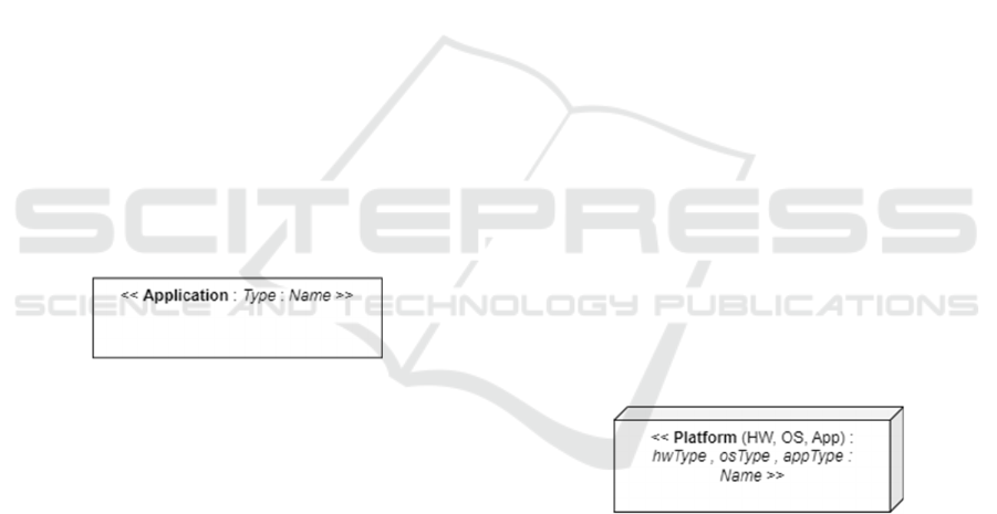
The application element suggested by this paper
can be seen as a wrapper for a group of related
components running on a platform. This paper
proposes using a rectangle with a label to model the
application element, as shown in Figure 2.
Figure 2: Proposed notation for the application element.
Based on the label format given in Figure 1, the
application element’s element segment is set as
application; the type segment should contain a
suitable value to denote the type of the application,
for example, browserApp, mobileApp, or webService.
Finally, the name segment may use a unique name to
identify the application element.
3.2.2 Platform Element
The platform comprises three levels: the hardware,
the operating system, and the application-level
virtualisation (see section 3.1.2). UML metamodel
uses the node model element to express the platform
details on the deployment diagram using two levels:
device and execution environment (uml-
diagrams.org, n.d.). The main issue with UML node
syntax is that multiple nested nodes should be used to
design the platform details, which reduces the
readability by making the design untidy.
The UML-based methods/tools use the UML
metamodel’s node to denote the platform, and they
inherit the same issues regarding the nested nodes, as
stated above. Arc42’s (Starke, 2023) Building Block
View enables depicting the platform; nevertheless, it
uses boxes and lines without proper modelling
elements. Arc42’s Deployment View uses the UML
node without additional dedicated notations.
Archimate’s Technology Layer uses the node as a
“computational or physical resource that hosts,
manipulates, or interacts with other computational or
physical resources” (Visual-Paradigm, 2018).
Archimate further provides more notations – such as
system software, technology function, technology
service, and technology collaboration – to include
platform-related details in a model. The complexity,
hence, the learning curve of Archimate, could be
increased by having many notations for the same
concept. SysML’s (OMG SysML, 2019) Block
Definition Diagram provides some notation like
AbstractDefinition, which can be exploited to include
the platform details into a model. The C4 model
(Brown, 2023) does not explicitly provide notations
for platforms; however, platform details can be
denoted in the level 2 Container diagram using
boxes.
Aligning with the standard UML, this paper
proposes the same node notation for the platform.
However, nested nodes are eliminated by exploiting
the label to provide more details on a single node to
increase the readability. The proposed notation is
named platform and is given in Figure 3.
Figure 3: Proposed notation for the platform element.
The following rules are provided to name the
platform element.
• The element segment of the label should be
“Platform”.
• In addition, in the element segment, within
brackets, the platform levels presented by the
element should be indicated using the shortcodes:
HW for hardware, OS for operating systems, and
App to denote the application-level virtualisation.
The levels should be separated using commas.
• For the type segment of the label, the technical
details of the platform levels mentioned in the
Applications Model: A High-Level Design Model for Rich Web-Based Applications
323
element segment should be specified in the same
order, separated by commas.
• The name segment of the label should contain
names for the platform levels for identification
purposes in the same order, separated by commas.
For example, a user’s browser in an Android
mobile phone can be labelled as depicted in Figure 4.
<< Platform (HW, OS, App) :
Mobile phone, Android, Browser :
User’s browser >>
Figure 4: Example of platform label.
3.2.3 Tier Element
Since the UML metamodel has no particular
diagrams for high-level design, there is no notation to
denote tiers. The UML package element’s notation
can be exploited to represent the layers as in layered
architecture; however, the layer’s concept is abstract
and does not explicitly align with the concept of the
tiers in RiWAs. Arc42’s (Starke, 2023) Building
Block View allows showing tiers on the architecture;
anyhow, it suggests using lines and boxes instead of
providing proper modelling elements for different
types of blocks, reducing the readability. TAM (SAP,
2007) (SAP, 2023) uses a dashed line to indicate the
protocol boundaries and explains that “Protocol
boundaries usually partition a diagram in order to
accentuate certain boundaries in communication.”
This notion of separation differs from the tier concept,
and it will not indicate the role or distribution of the
containing elements. Archimate’s (The Open Group,
2023) physical layer provides some containers:
Equipment, Facility, Distribution Network, and
Material for different levels of separation;
nevertheless, they do not provide a high level of
simplicity similar to tier. SysML provides a more
abstract concept called Block, which is likely to be
used to denote tier (OMG SysML, 2019). The Block
“defines a collection of features to describe a system
or other element of interest” (OMG SysML, 2019),
and it can be exploited to model tiers.
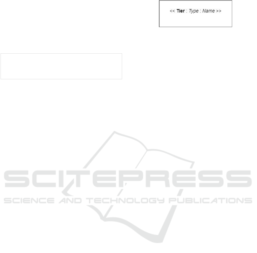
This paper suggests using a rectangular block to
indicate the tier, as given in Figure 5. The adjacent
tiers may share the side borderlines, as shown in
Figure 6. The tier label’s element segment should use
the “Tier” keyword. Since the RiWAArch style is
based on the 3-tier architecture, this paper only
specifies three values for the type segment of the
label: Presentation, Application, and Storage. The
name segment may contain a suitable value to
identify the tier based on the system’s requirements.
Figure 5: Proposed notation for the tier element.
3.3 Proposed Applications Model
The highest level of the RiWA architecture comprises
a set of applications running on different platforms
distributed in different tiers and requires a model to
realise these elements, their configurations, and
related details.
UML does not provide any models for
architectural design. UML metamodel uses the
deployment diagram to design the platform details,
and UML-based methods mainly utilise the
deployment diagram to denote the platform and
related details. The deployment diagram does not
show application elements and/or explain the
grouping of platforms into tiers, and may use multiple
levels of nested nodes to denote the complete
platform details, reducing the design’s readability.
TAM (SAP, 2007) uses the Component/Block
diagram to model the architecture, which shows a
tier-like separation primarily based on the
communication protocol and does not include
platform details and no dedicated notation for
application elements. Arc42’s (Starke, 2023)
Building Block View tries to capture the architectural
elements but lacks proper syntax and definitions. The
C4 model’s Container diagram provides guidelines
to capture the application elements; however, it does
not have formal notations and rules and, hence, lacks
readability.
This paper proposes the Applications model to
satisfy the requirements set in section 3.1. The
application model utilises the proposed elements: tier,
platform, and application. The Applications diagram
shows all the application elements in a RiWA, uses a
single platform element per application, and the
platforms are grouped into tiers. The communication
channels between the applications should also be
denoted on the diagram to specify the configuration
of the elements.
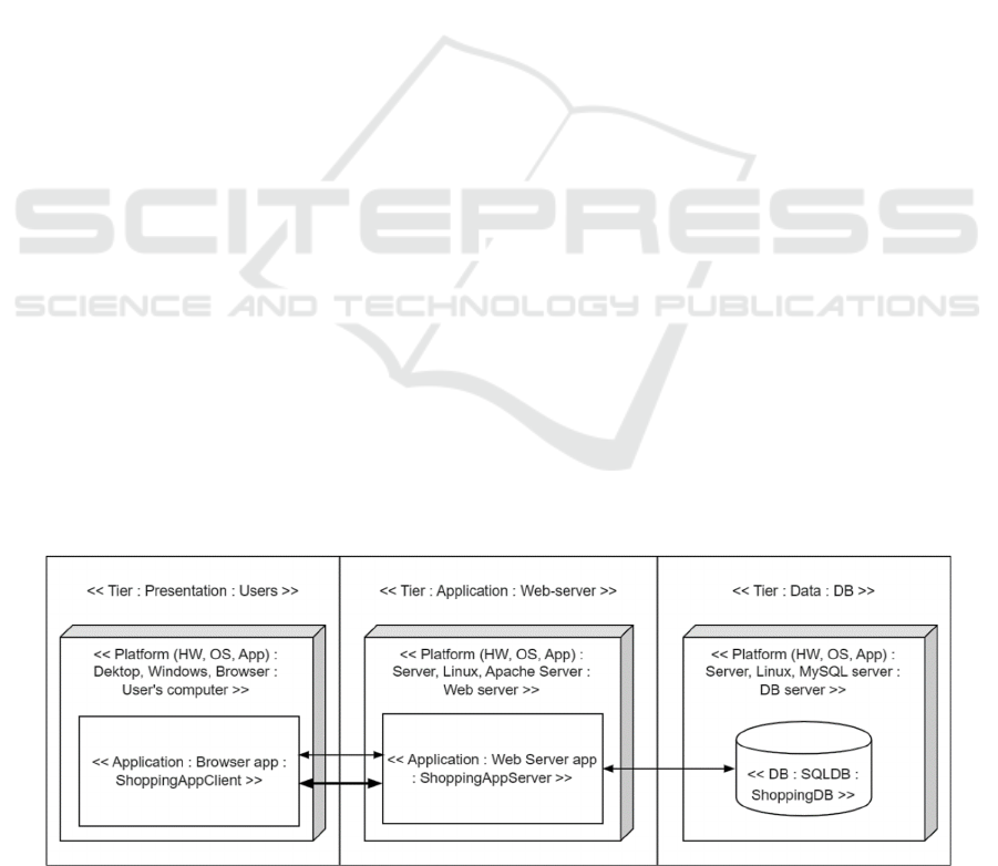
Figure 6 illustrates an example Applications
diagram for an online shopping RiWA. Two types of
arrows are depicted between the ShoppingAppClient
and the ShoppingAppServer: the thin arrow represents
the standard HTTP communication, and the thick
arrow indicates DC (Dissanayake & Dias, 2017). In-
depth discussions on the communication channels are
kept out of this paper.
ENASE 2024 - 19th International Conference on Evaluation of Novel Approaches to Software Engineering
324
4 USE CASES
This paper presents Applications diagrams of two
real-world use cases as proof of concept.
4.1 Use Case 1, LMS
The first use case is a graph-based learning and
knowledge management system (LMS) named
Smartest (Bolotov, 2020), which was initially
developed as a regular web application. In the next
stage, the following improvements were required.
• Convert the system to a RiWA with two types of
client apps: browser app and mobile app.
• Move domain logic to a web service, which is
exposed to both types of clients via RESTful
APIs.
We worked on re-architecting the system for a
smooth transition, and we designed the Applications
diagram for the target version given in Figure 7,
which realises the application elements in the final
system and the communication between them in
HTTP and/or DC form.
This Applications diagram helped make decisions
on deploying the application elements in the
application and the storage tiers. Besides, the
Applications diagram assists in identifying the
internal components and connectors of the
application elements, which helped in the low-level
design and development.
4.2 Use Case 2, MICADO-Edge
MiCADO-Edge (Ullah, et al., 2021) is a model for
cloud-to-edge computing. Our ongoing research has
focused on the basic 3-tier browser-based RiWAs.
Despite this use case being out of the context of basic
RiWAs, it was selected to experiment with to
understand the potential of the applications model.
The original architecture in the published paper
(Ullah, et al., 2021) uses the box and line approach;
thus, it is incomplete and has many unanswered
questions regarding the types of the elements and
their configuration. We are working with the
MiCADO-Edge researchers to produce the design
diagrams using the design language introduced by our
ongoing research, and as the first step, the MiCADO-
Edge architecture is reproduced using the
applications model. The reproduced MiCADO-Edge
architecture is given in Figure 8, which includes more
details about the tiers and platforms and is more
readable than the original diagram.
The Cloud tier represents a cloud platform;
therefore, a platform element is not used to denote the
cloud platform explicitly. Since this is more of an
architectural style, actual HW and OS platform
details for the edge and fog devices are not given. If
standard UML node elements were used for them,
nested nodes in two levels would be required to depict
the HW and OS platforms, which could make the
diagram untidy, reducing the readability.
5 CONCLUSION AND FUTURE
WORK
Achieving the objectives set up in Section 1.3, the
research presented in this paper has the following
main contributions: (1) definition of the requirements
for the proposed applications model and its elements:
tier, platform, and application; (2) the notations for
these elements; and (3) introduction of the
applications model.
The use cases in section 4 evidence that the
proposed platform notation is capable of denoting the
required details of an application’s platform using a
Figure 6: An example Applications diagram.
Applications Model: A High-Level Design Model for Rich Web-Based Applications
325
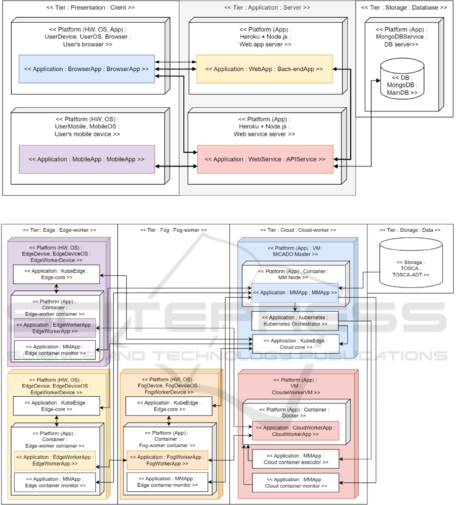
Figure 7: Applications diagram of the Smartest LMS.
Figure 8: Applications diagram of MiCADO-Edge.
single element in a much more readable format
compared to the UML node. The tier element is able
to group and organise the application elements with
corresponding platform elements, improving the
simplicity. These elements help the applications
model contain high-level details of a RiWA while
maintaining the diagram simple, tidy, and readable.
The use case shows that the Applications diagram is
capable of realising systems with IoT and cloud
computing features.
In future, we expect to introduce another high-
level model and its modelling elements to design
RiWAs views, components, and connectors within
application elements. Also, we will continue working
on low-level models and modelling elements to
design the detailed aspects of the views, controllers,
ENASE 2024 - 19th International Conference on Evaluation of Novel Approaches to Software Engineering
326

and models of application elements. With all the new
models and modelling elements, we expect to
introduce a set of UML profiles for a new UML
extension to cater for the specificity of RiWAs.
Further, we plan to widen the scope of the research to
address RiWAs designing, which are integrated with
elements for related concepts like cloud computing,
the Internet of Things, Artificial Intelligence and
Machine Learning.
REFERENCES
Avritzer, A., Paulish, D., Cai, Y., & Sethi, K. (2010).
Coordination implications of software architecture in a
global software development project. The Journal of
Systems and Software, 83(10), 1881-1895.
Bolotov, A. Pierantoni, G., Chan You Fee, D., Wojtunik, D.,
Ivanauskaite, G., Tait, C., Makadicy, W., Wasowski, T.,
Kulczynska, A. and Yerashenia, N. (2020). SMARTEST
- knowledge and learning repository. Retrieved Dec 10,
2023, from Westminster Research: https://westminster
research.westminster.ac.uk/item/v2x13/smartest-knowle
dge-and-learning-repository
Brown, S. (2023). The C4 model for visualising software
architecture. (https://simonbrown.je/) Retrieved Dec
10, 2023, from https://c4model.com/
Dissanayake, N. R., & Dias, G. (2017). Delta
Communication: The Power of the Rich Internet
Applications. International Journal of Future
Computer and Communication, 6(2), 31-36.
Dissanayake, N. R., & Dias, G. K. (2016). Abstract
concepts: A contemporary requirement for Rich
Internet Applications engineering. 9th International
Research Conference of KDU (KDU-IRC 9). Colombo,
Sri Lanka.
Dissanayake, N. R., & Dias, K. (2018). Rich Web-based
Applications: An Umbrella Term with a Definition and
Taxonomies for Development Techniques and
Technologies. International Journal of Future
Computer and Communication, 7(1), 14-20.
Dissanayake, N. R., & Dias, K. (2020). RiWAArch Style:
An Architectural style for Rich Web-based
Applications. Arai K., Kapoor S., Bhatia R. (eds)
Proceedings of the Future Technologies Conference
(FTC) 2020, Volume 3. FTC 2020. Advances in
Intelligent Systems and Computing, vol 1290. Springer
(pp. 292-312). Canada: Springer, Cham.
Fielding, R. T. (2000). Architectural Styles and the Design
of Network-based Software Architectures. Irvine:
University of California.
Fuentes, L., & Vallecillo, A. (2004). An introduction to
UML profiles. UPGRADE The European Journal for
the Informatics Professional, V(2), 6-13.
Hough, D. (1993). Rapid Delivery: An eveolutionary
approach for application development. IBM SYSTEM
JOURNAL, 32(3), 397-419.
Koning, H., Dormann, C., & Vliet, H. v. (2002). Practical
guidelines for the readability of IT-architecture
diagrams. SIGDOC ’02: Proceedings of the 20th
annual international conference on Computer
documentation (pp. 90-99). ACM.
Laplante, P. A. (2007). What Every Engineer Should Know
About Software Engineering. CRC Press.
OMG. (2023, Jun). OMG Systems Modeling Language
Version 2.0 Beta 1. OMG.
OMG. (2023). Unified Modeling Language (UML). (Object
Management Group) Retrieved Dec 10, 2023, from
http://www.uml.org
OMG SysML. (2019). OMG Systems Modeling Language
version 1.6. OMG SysML.
Ozkaya, M., & Kloukinas, C. (2013). Are We There Yet?
Analysing Architecture Description Languages for
Formal Analysis, Usability, and Realizability. 2013
39th Euromicro Conference on Software Engineering
and Advanced Applications.
Santander, Spain.
Richards, M. (2022). Software Architecture Patterns.
O’Reilly Media, Inc.
SAP. (2007). Standardised Technical Architecture
Modeling - Conceptual and Design Level. SAP.
SAP. (2023). Object-Oriented Architecture (16.7.07 –
2023-05-29 ed.). SAP.
Solutions, A. (2014). The Importance of Software
Architecture. Architech Solutions.
Starke, G. (2023). arc42. (arc42) Retrieved Dec 10, 2023,
from https://arc42.org
The Institute of Electrical and Electronics Engineers, I.
(2002). IEEE Standard Glossary of Software
Engineering Terminology.
The Open Group. (2023, 01 03). ArchiMate® 3.2
Specification. (The Open Group) Retrieved Dec 10,
2023, from https://pubs.opengroup.org/architecture/
archimate32-doc/
Ullah, A., Dagdeviren, H., Ariyattu, R. C., DesLauriers, J.,
Kiss, T., & Bowden, J. (2021). MiCADO-Edge:
Towards an Application-level Orchestrator for the
Cloud-to-Edge Computing Continuum. Journal of Grid
Computing, 19(47).
uml-diagrams.org. (n.d.). Deployment Diagrams Overview.
(uml-diagrams.org) Retrieved Dec 10, 2023, from
https://www.uml-diagrams.org/deployment-diagrams-
overview.html
uml-diagrams.org. (n.d.). UML Artifact. (uml-
diagrams.org) Retrieved Dec 10, 2023, from
https://www.uml-diagrams.org/artifact.html
Visual-Paradigm. (2018, Feb 21). ArchiMate Notation:
Part 1 – Business Layer. (Visual-Paradigm) Retrieved
Dec 10, 2023, from https://archimate.visual-paradigm.
com/archimate-notation-part-1-business-layers/
Visual-Paradigm. (2018, Feb 20). ArchiMate Notation:
Part 3 – Technology Layer. (Visual-Paradigm)
Retrieved Dec 10, 2023, from https://archimate.visual-
paradigm.com/archimate-notation-part-3-technology-
layers/
Zuse, H. (1992). Software Complexity Measures and
Models. New York: de Gruyter & Co.
Applications Model: A High-Level Design Model for Rich Web-Based Applications
327
