
Steady-State Energy Consumption Evaluation in BaseBand Units Pool in
Cloud Radio Access Network
Maroua Idi
1 a
, Sana Younes
1 b
and Riadh Robbana
2 c
1
Faculty of Sciences of Tunis, University of Tunis El Manar, Tunis 2092, Tunisia
2
National Institute of Applied Sciences and Technology, University of Carthage, Tunis 1080, Tunisia
Keywords:
C-RAN, Energy Efficiency, Hysteresis, MRM, CTMC, CSRL.
Abstract:
Cloud Radio Access Network (C-RAN) have been proposed as a fifth-generation (5G) cellular network so-
lution for high spectral and energy efficiency. In the C-RAN architecture, which leverages cloud computing
technology, the baseband processing is performed in the cloud. In fact, the BaseBand Units (BBUs) are located
in the cloud and generate Virtual Machines (VMs) to serve User Equipment (UE) calls. This paper performs
a quantitative analysis of the energy consumption computed over two schemes named Virtual Machine Hys-
teresis Allocation Strategy (VMHAS) and Virtual Machine Allocation Strategy (VMAS) for 5G C-RAN. The
first, VMHAS, uses the hysteresis mechanism to minimize energy consumption by adjusting the number of
VMs in BBUs according to the traffic load. It consists of switching the idle VMs to sleep mode to save energy.
The second, VMAS, allocates VMs without considering the sleep mode. We use the Markov Reward Model
(MRM) to evaluate measures related to energy consumption in the proposed schemes. Modeling and per-
formance measures specification are achieved by Continuous-Time Markov chains (CTMCs) and Continuous
Stochastic Reward Logic (CSRL). We quantify the steady-state performance measures by checking CSRL for-
mulas using the PRISM model checker. The obtained results demonstrate that the scheme with the hysteresis
mechanism, VMHAS, achieves an enhanced energy performance compared to VMAS.
1 INTRODUCTION
Cloud Radio Access Network (C-RAN) architecture
(Checko et al., 2014) has been proposed as a one of
the fifth generation (5G) cellular networks for pro-
viding high spectral efficiency and conserving en-
ergy. By leveraging cloud computing technology, C-
RAN implements the functional separation of tradi-
tional Base Station into two parts: the BaseBand Unit
(BBU) and the Remote Radio Head (RRH). C-RAN
moved all the BBUs to a central unit called the BBU
pool. Meanwhile, the RRHs are left off on the cell
sites. The connection between the BBUs and RRHs,
respectively responsible for baseband and radio func-
tionalities, is referred to as the fronthaul links and is
done via an optical transport network.
Several researchers have focused on improving
the energy efficiency of C-RAN using the ON-OFF
switching (also known as sleep mode) technique.
a
https://orcid.org/0000-0002-6467-8887
b
https://orcid.org/0000-0002-4883-3381
c
https://orcid.org/0000-0001-5736-4137
Considering that the RRHs only solely function as
transmitters/receivers with minimal energy consump-
tion, the energy conservation achieved by deactivat-
ing (sleep mode) RRHs would be restricted (Feng
et al., 2017). Therefore, it is highly appealing to in-
vestigate the ON-OFF switching for BBUs. Many
works (Sigwele et al., 2017) (Aldaeabool and Abbod,
2017) (Sahu et al., 2017) have studied the deactivating
mechanism for BBUs in C-RAN. Nonetheless, deacti-
vating a BBU affects all its associated RRHs and User
Equipment (UE) connected to those RRHs. Hence,
the activation and deactivation conditions of BBUs
are interconnected with the mappings between BBU-
RRH and RRH-UE. Since, in the C-RAN architec-
ture, all BBU functions are implemented on standard
hardware and executed on Virtual Machines (VMs)
(Yu et al., 2017) which serve UEs. Therefore, a more
accurate adjustment of the number of VMs in a BBU
that can support would improve the network capacity
and the energy efficiency which is the target for this
paper.
This paper continues the work proposed in (Idi
et al., 2022), in which a new Call Admission Con-
Idi, M., Younes, S. and Robbana, R.
Steady-State Energy Consumption Evaluation in BaseBand Units Pool in Cloud Radio Access Network.
DOI: 10.5220/0012629400003687
Paper published under CC license (CC BY-NC-ND 4.0)
In Proceedings of the 19th International Conference on Evaluation of Novel Approaches to Software Engineering (ENASE 2024), pages 99-109
ISBN: 978-989-758-696-5; ISSN: 2184-4895
Proceedings Copyright © 2024 by SCITEPRESS – Science and Technology Publications, Lda.
99

trol (CAC) scheme was proposed. This scheme,
called Virtual Machine Hysteresis Allocation Strategy
(VMHAS), aims to adjust the number of active VMs
in BBUs by making non-used VMs in sleep mode. To
achieve this, VMHAS utilizes the hysteresis mecha-
nism by dividing the VMs of BBUs into levels. Each
level will be activated when the number of used VMs
attains an activated threshold. Similarly, the level is
deactivated when the number of used VMs is less than
a deactivation threshold. Only the call-blocking prob-
ability was evaluated without considering the main
performance measure related to the energy consump-
tion that the scheme should enhance. It is the main
contribution of this paper in which we focus on evalu-
ating energy consumption. To show the effectiveness
of the VMHAS scheme, we compare the system’s en-
ergy consumption under this allocation strategy with
a new traditional scheme, called Virtual Machine Al-
location Strategy (VMAS), that does not consider the
VM sleep mode.
We use the Markov Reward Model (MRM) to
evaluate energy consumption measures in this work’s
proposed schemes. MRM (Katoen et al., 2005)
is a mathematical model used to describe and ana-
lyze the behavior of a system over time. It com-
bines a continuous-time Markov model and a set
of reward functions. We model CAC schemes by
Continuous-Time Markov Chains (CTMCs) (Kulka-
rni, 2016) and specify performance measures by Con-
tinuous Stochastic Reward Logic (CSRL) (Haverkort
et al., 2002). We quantify the steady-state perfor-
mance measures by checking CSRL formulas using
the PRISM model checker.
The work contains the following contributions:
1. We perform a quantitative analysis of the en-
ergy consumption computed over an MRM of the
hysteresis-based CAC scheme VMHAS.
2. We model a new traditional scheme VMAS with
an MRM and quantify the energy consumption
relative to this scheme.
3. We use the PRISM model checker to perform
modeling, specification, and quantification of the
steady-state reward measures of CAC schemes
(VMHAS and VMAS) by checking CSRL formu-
las.
4. We perform a comparative analysis of the en-
ergy consumption between VMHAS and VMAS
schemes. Results show that the VMHAS scheme
performs better than VMAS in saving energy un-
der low and medium traffic.
The remainder of this paper is organized as fol-
lows. Section 2 is devoted to the related work. In sec-
tion 3, we introduce the MRM and CSRL logic. Sec-
tion 4 provides a formal modeling of CAC schemes.
Section 5 presents a formal specification of steady-
state reward requirements. Section 6 gives numerical
results. Finally, section 7 concludes the paper.
2 RELATED WORK
Several works are related to the energy efficiency in
C-RAN. In (Sigwele et al., 2015), authors proposed a
green intelligent Traffic and Resource Elastic Energy
CAC scheme called iTREE. In iTREE, the number
of used BBUs is reduced to equal the correct amount
of the traffic load (Idle BBUs can then turn to sleep
mode). To minimize the energy consumption in C-
RAN, the authors proposed an approximation heuris-
tic bin-packing algorithm. The work in (Sigwele
et al., 2017) is an extension of (Sigwele et al., 2015),
in which authors proposed an energy reduction model
for C-RAN architecture that considers workload con-
solidation of BBUs located in the cloud. The idea of
the model is to act with a fixed amount of BBUs and,
according to the demand, deactivate the idle BBUs
and reactivate them only in case of overloading. The
proposed model reduces the total consumption of en-
ergy and saves resources. In (Aldaeabool and Ab-
bod, 2017), authors proposed a strategy for switching
a BBU between On/Off modes according to the traf-
fic load in the associated RRH. In fact, they proposed
a host server in the BBU pool that hosts a Modified
Best Fit Decreasing (MBFD) algorithm. They formu-
lated an optimization problem of reducing the num-
ber of BBUs with low loads by transferring them to
neighboring BBUs with the available capacity. Simu-
lation results demonstrated that the MBFD algorithm
performs better than traditional ones by minimizing
the number of active BBUs and the power consump-
tion for normalized traffic load. The authors studied
in (Zhang et al., 2016) the BBU pool energy con-
sumption problem under a tidal traffic scenario. By
developing heuristic algorithms, the number of active
BBUs is minimized. In (Sahu et al., 2017), a scheme
based on the graph method to reduce the energy con-
sumption in the BBU pool is proposed. Simulation
results show that the proposed algorithm reduces en-
ergy consumption by about 20%. In (Alhumaima
et al., 2018), authors introduced the problem of allo-
cating an optimal number of VMs to the cloud server.
They used Monte Carlo-based evolutionary algorithm
to reach the suboptimal number of VMs that opti-
mizes C-RAN energy efficiency. In (Mai et al., 2023),
the authors proposed an optimization model for sys-
tem energy efficiency that jointly allocates multiple
resources for C-RAN downlink transmission.
ENASE 2024 - 19th International Conference on Evaluation of Novel Approaches to Software Engineering
100

3 MARKOV REWARD MODEL
MRM (Katoen et al., 2005) is a mathematical model
used to describe and analyze the behavior of a sys-
tem over time. It combines the principles of Markov
chains and rewards to quantify the expected rewards
associated with different states in the system. In this
work, we consider a continuous-time Markov reward
model, which is a combination of a CTMC with a re-
ward function associated with states of the chain. For-
mally, a CTMC M is a tuple (S, R) where S is a set of
states and R : S × S → R
+
is the rate matrix (Kulka-
rni, 2016).
For a CTMC, there are two types of state proba-
bilities: transient probabilities, where the system is
considered at time t, and steady-state probabilities,
when the system reaches an equilibrium if it exists.
Let Π
M
s
(s
′
) be the steady-state probability to be in
state s
′
starting from the initial state s. If M is er-
godic, Π
M
s
(s
′
) exists, and it is independent of the ini-
tial distribution that we will denote by Π
M
(s
′
). Let
Π
M
be the steady-state probability vector. For S
′
⊆ S,
we denote Π
M
(S
′
) the steady-state probability to be
in states of S
′
, Π
M
(S
′
) =
∑
s
′
∈S
′
Π
M
(s
′
).
In order to specify and check performance re-
quirements over a RMM, we use CSRL (Haverkort
et al., 2002), which is an extension of Continu-
ous Stochastic Logic (CSL) (Aziz et al., 2000) by
adding constraints over rewards. CSL is a tempo-
ral logic that provides ample means to specify state
and path-based performance measures for CTMC but
does not support reward formulas. Therefore, we use
the CSRL, which contains reward operators that re-
fer to the stationary and transient behavior of the sys-
tem under consideration. This paper concentrates on
model-checking procedures for steady-state perfor-
mance measures. Indeed, we will use the steady-state
reward formula E
J
(φ), which asserts that the long run
reward rate in S
φ
(States that satisfy the formula φ)
lies in J (J is an interval of real numbers).
Let ρ : S → R
+
be a reward structure that assigns
to each state s ∈ S a reward value ρ(s). The verifica-
tion of this reward formula E
J
(φ) requires the compu-
tation of the steady-state distribution Π
M
s
of the con-
sidered M .
s |= E
J
(φ) iff
∑
s
′
∈S
φ
Π
M
(s
′
) · ρ(s
′
) ∈ J
(1)
4 FORMAL MODELING OF THE
CONSIDERED CAC SCHEMES
This paper considers a C-RAN system with a cell con-
taining a certain number of RRHs and a centralized
BBU pool of K BBUs. Each BBU comprises a set of
VMs; it could serve each UE by generating a VM. We
suppose that each UE has its corresponding VM i.e. a
VM can only serve one UE. We also assume that all
BBUs are identical: They have the same performance
and they support the same number of VMs.
In the following, we will formally describe and
model the two CAC schemes (VMHAS and VMAS).
4.1 Formal Model of VMHAS Scheme
In this subsection, we recall from (Idi et al., 2022) the
basic concept of VMHAS and give its corresponding
Markov chain rate matrix.
4.1.1 VMHAS Description
The VMHAS scheme uses the hysteresis mechanism
to save energy in the C-RAN system. In fact, since
the energy consumption of an idle VM (activated VM
waiting for a call) is 60 to 80 percent of that of a
busy VM (VM occupied by a call) (Duan et al., 2015).
Therefore we use the hysteresis mechanism to divide
each BBU into three levels of VMs. A VM can be in
three modes: sleep, idle, or busy, as shown in Fig.1. A
VM in sleep mode is a deactivated VM and consumes
the lowest energy compared to its consumption in the
other modes.
Active
Idle BusySleep
Figure 1: VM modes.
Initially, for all BBUs, we suppose that VMs in
the first level are activated and are in idle mode, while
the remaining VMs belonging to the other levels are
in sleep mode. When a call arrives, it will be assigned
to the available VM in the least-load BBU; there-
fore, it passes from idle to busy mode. By default,
when the current traffic load is the same in all BBUs,
the first BBU will serve the incoming call. When
the number of VMs in busy mode reaches the first
hysteresis-activated threshold (V m
1
), the second level
will be activated (VMs of the second level pass from
sleep mode to idle mode). Similarly, the third level in
all BBUs will be activated when the number of busy
VMs reaches the second hysteresis-activated thresh-
old (V m
2
). The hysteresis mechanism supposes that
the deactivation thresholds differ from the activation
thresholds to avoid redundant activation/deactivation
of levels containing only VMs in idle mode. These
Steady-State Energy Consumption Evaluation in BaseBand Units Pool in Cloud Radio Access Network
101

thresholds: T
1
for the deactivation of the second level
and T
2
for the deactivation of the third level, are
respectively less than their corresponding activation
levels (V m
1
and V m
2
).
Let us recall that V
max
is the maximum number of
VMs in a BBU, and K is the total number of BBUs.
We assume that the call arrival process follows the
Poisson distribution with the following mean rates:
λ. We suppose that the holding time of VM is expo-
nentially distributed with mean 1/µ and independent
from the arrival process.
Based on these assumptions, the VMHAS scheme
(Idi et al., 2022) is modeled by a multidimen-
sional homogeneous CTMC. In the case of K-BBUs,
a state of the CTMC is represented by the tuple
(i
1
,i
2
.··· , i
k
,··· , i
K
,l), where i
k
represents the num-
ber of VMs in the busy mode in the k
th
BBU, where
1 ≤ k ≤ K. l represents the activated level of VMs
which can be equal to 1, 2, or 3.
4.1.2 Markov Chain for Two BBUs
To represent the VMHAS model, we use a labeled
Markov model in the case of two BBUs (K = 2), as
VMHAS is modeled by CTMC consisting of a large
number of components, where each dimension rep-
resents the number of active VMs in the BBU. We
recall from (Idi et al., 2022) the Markov state space
of VMHAS. We then present their rate matrix in the
particular case of two BBUs.
Markov Chain State Space. In the case of two
BBUs, the VMHAS scheme is modeled by a three-
dimensional CTMC. The obtained CTMC is com-
posed of three blocks relative to the number of lev-
els in the hysteresis mechanism. Therefore, the state
space S
′
is composed of three subsets: S
′
1
, S
′
2
and S
′
3
.
The subset S
′
1
(resp. S
′
2
) (see Eq.2 and Eq.3) contains
states relatives to the activation of the first (resp. the
second) level of VMs. S
′
3
(see Eq.4) contains states
relatives to the activated VMs of the third block.
Therefore, the whole state space is given by:
S
′
= S
′
1
∪ S
′
2
∪ S
′
3
In state (i, j,l), i (resp. j) represents the number
of busy VMs in BBU
1
(resp. BBU
2
), and l represents
the activate level of VMs (1, 2 or 3):
S
′
1
= {(i, j,1);1 ≤ i ≤ V m
1
and 0 ≤ j ≤ i − 1}
∪ {(i, j,1);0 ≤ j ≤ V m
1
− 1 and 0 ≤ i ≤ j}
(2)
S
′
2
= {(i, j,2);T
1
≤ i ≤ V m
2
and 0 ≤ j ≤ i − 1}
∪ {(i, j,2);T
1
≤ j ≤ V m
2
− 1 and 0 ≤ i ≤ j}
(3)
S
′
3
= {(i, j,3);T
2
≤ i ≤ V
max
and 0 ≤ j ≤ i − 1}
∪ {(i, j,3);T
2
≤ j ≤ V
max
and 0 ≤ i ≤ j}
(4)
Markov Chain Rate Matrix. Transition rates
R
′
(s;(
¯
i,
¯
j,
¯
l)) from the state s = (i, j, l) to the state
(
¯
i,
¯
j,
¯
l) are defined as:
• Markov Rates due only to the arrival of calls.
– Rates when the first level is activated.
*
A call arrives and assigned to a VM in the first
BBU.
R
′
(s = (i, j,1);(i + 1, j, 1)) = λ if
{
0 ≤ i ≤ j ≤ V m
1
− 1
}
*
A call arrives and assigned to a VM in the sec-
ond BBU.
R
′
(s = (i, j,1);(i, j + 1, 1)) = λ if
{
1 ≤ i ≤ V m
1
− 1; 0 ≤ j ≤ i − 1
}
or
{
i = V m
1
;0 ≤ j ≤ V m
1
− 2
}
*
A call arrives and assigned to a VM in the sec-
ond BBU and the second level of VMs is acti-
vated.
R
′
(s = (i, j,1);(i, j + 1, 2)) = λ if
{
i = V m
1
; j = V m
1
− 1
}
– Rates when the first and the second level are
activated.
*
A call arrives and assigned to a VM in the first
BBU.
R
′
(s = (i, j,2);(i + 1, j, 2)) = λ if
{
0 ≤ i ≤ j; T
1
≤ j ≤ V m
2
− 1
}
*
A call arrives and assigned to a VM in the sec-
ond BBU.
R
′
(s = (i, j,2);(i, j + 1, 2)) = λ if
{
T
1
≤ i ≤ V m
2
− 1; 0 ≤ j ≤ i − 1
}
or
{
i = V m
2
;0 ≤ j < V m
2
− 2
}
*
A call arrives and assigned to a VM in the sec-
ond BBU and the third level of VMs is acti-
vated.
R
′
(s = (i, j,2);(i, j + 1, 3)) = λ if
{
i = V m
2
; j = V m
2
− 1
}
– Rates when all levels are activated.
*
A call arrives and assigned to a VM in the first
BBU.
R
′
(s = (i, j,3);(i + 1, j, 3)) = λ if
{
0 ≤ i ≤ j; T
2
≤ j ≤ V
max
}
ENASE 2024 - 19th International Conference on Evaluation of Novel Approaches to Software Engineering
102

*
A call arrives and assigned to a VM in the sec-
ond BBU.
R
′
(s = (i, j,3);(i, j + 1, 3)) = λ if
{
T
2
≤ i ≤ V
max
;0 ≤ j ≤ i − 1
}
or
{
i = V
max
;0 ≤ j < V
max
− 1
}
• Markov Rate due only to the departure of calls.
– Rates when the first level is activated.
*
A VM is released from the first BBU.
R
′
(s = (i, j,1);(i − 1, j, 1)) = iµ if
{
0 < i ≤ V m
1
;0 ≤ j ≤ V m
1
− 1
}
*
A VM is released from the second BBU.
R
′
(s = (i, j,1);(i, j − 1, 1)) = jµ if
{
0 < i ≤ V m
1
;0 ≤ j ≤ V m
1
− 1
}
– Rates when the second level is activated.
*
A VM is released from the first BBU.
R
′
(s = (i, j,2);(i − 1, j, 2)) = iµ if
{
0 < i ≤ j; T
1
≤ j ≤ V m
2
− 1)
}
or
{
T
1
< i ≤ V m
2
;0 ≤ j ≤ i − 1
}
*
A VM is released from the second BBU.
R
′
(s = (i, j,2);(i, j − 1, 2)) = jµ if
{
T
1
≤ i ≤ V m
2
;0 < j ≤ i − 1
}
or
{
0 ≤ i ≤ j; T
1
< j ≤ V m
2
− 1
}
or
{
i = T
1
; j = T
1
}
*
Following the departure of a call, the second
level of VMs is deactivated.
R
′
(s = (i, j,2);(i, j − 1, 1)) = jµ if
{
0 ≤ i < T
1
; j = T
1
}
R
′
(s = (i, j,2);(i − 1, j, 1)) = iµ if
{
i = T
1
;0 ≤ j < T
1
}
– Rates when all levels are activated.
*
A VM is released from the first BBU.
R
′
(s = (i, j,3);(i − 1, j, 3)) = iµ if
{
0 < i ≤ j; T
2
≤ j ≤ V
max
}
or
{
T
2
< i ≤ V
max
;0 ≤ j ≤ i − 1
}
*
A VM is released from the second BBU.
R
′
(s = (i, j,3);(i, j − 1, 3)) = jµ if
{
i = T
2
; j = T
2
}
or
{
T
2
≤ i ≤ V
max
;0 < j ≤ i − 1
}
or
{
0 ≤ i ≤ j; T
2
< j ≤ V
max
}
*
Following the departure of a call, the third
level of VMs is deactivated.
R
′
(s = (i, j,3);(i, j − 1, 2)) = jµ if
{
0 ≤ i < T
2
; j = T
2
}
R
′
(s = (i, j,3);(i − 1, j, 2)) = iµ if
{
i = T
2
;0 ≤ j < T
2
}
4.2 Formal Model of VMAS Scheme
In order to assess the effectiveness of the VMHAS
scheme, we have chosen to compare it with the
VMAS model, which does not consider VM sleep
mode. Indeed, in the VMAS scheme, all the VMs in
all BBUs are always activated. Therefore, when a call
arrives, it will be assigned to the available VM in the
least-load BBU. By default, when the current traffic
load is the same in all BBUs, the first BBU will serve
the incoming call.
4.2.1 Algorithmic Description
The algorithmic description of the VMAS scheme in
the case general of K-BBUs is presented in Algorithm
1. Notes that the arrival of different calls and the de-
parture of ongoing calls cannot trigger simultaneously
due to the Markovian hypothesis.
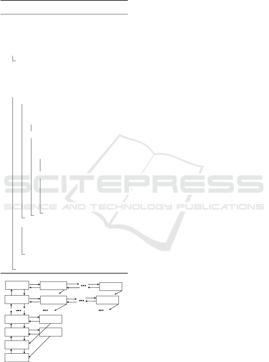
4.2.2 Markov Chain of VMAS
In the case of K-BBUs, a state of the CTMC is rep-
resented by (i
1
,i
2
.··· , i
k
,··· , i
K
), where i
k
represents
the number of VMs in the busy mode in the k
th
BBU,
1 ≤ k ≤ K. Let us remark that a state in VMAS does
not contain the l component (as for VHMAS) because
a BBU is considered with one level of VMs that are
always activated.
Similarly to the VMHAS scheme, we formally
present the Markov chain of the VMAS in the case of
two BBUs. It is presented in Fig.2 and defined with
the following state space:
S
′
= {(i, j); 1 ≤ i ≤ V
max
and 0 ≤ j ≤ i − 1}
∪ {(i, j); 0 ≤ j ≤ V
max
and 0 ≤ i ≤ j}
(5)
For VMAS, the transition rates R
′
(s;(
¯
i,
¯
j)) from
the state s = (i, j) to the state (
¯
i,
¯
j) are defined as:
• A call arrives and assigned to a VM in the first
BBU.
R
′
((i, j); (i + 1, j)) = λ if
{
0 ≤ i ≤ j < V
max
}
• A call arrives and assigned to a VM in the second
BBU.
R
′
((i, j); (i, j + 1)) = λ if
{
1 ≤ i ≤ V
max
;0 ≤ j ≤ i − 1
}
• A VM is released from the first BBU.
R
′
((i, j); (i − 1, j)) = iµ if
{
0 < i ≤ V
max
;0 ≤ j ≤ V
max
}
• A VM is released from the second BBU.
R
′
((i, j); (i, j − 1)) = jµ if
{
0 ≤ i ≤ V
max
;0 < j ≤ V
max
}
Steady-State Energy Consumption Evaluation in BaseBand Units Pool in Cloud Radio Access Network
103
Algorithm 1: Proposed algorithm of VMAS scheme in
the case of K-BBUs.
K: Total number of BBUs;
V
max
: Max number of VMs in a BBU;
V
k
: Number of VMs in busy mode in the k
th
BBU where ( 1 ≤ k ≤ K);
/* All BBUs are empty. */
for (1 ≤ k ≤ K) do
V
k
= 0
/* Two call verification methods:
arrival and departure. */
CallA = CallArrived();
CallD = CallDeparture();
while (CallA or CallD) do
if CallA then
/* Put the call in the first
BBU. */
if (∀ 1 ≤ k ≤ K,V
1
= V
2
... = V
K
) then
V
1
= V
1
+ 1;
else
/* Put the call in the
least loaded BBU. */
if (∀ 1 ≤ k ≤ K,V
k
< V
max
) then
V
l
= min V
k
;
V
l
= V
l
+ 1;
else
/* Call rejected: all VMs
in all BBUs occupied
(∀ 1 ≤ k ≤ K,V
k
= V
max
).
*/
Reject call ;
if CallD then
/* Function returning a BBU from
which a call departed. */
k = departedcall();
V
k
= V
k
− 1;
CallA = CallArrived();
CallD = CallDeparture();
0,0
λ
µ
1,0
λ
µ
1,1 0,1
µ
λ
λ
2µ
2,1 2,0
λ
µ
µ
2µ
λ
2µ
λ
Vmax,Vmax-1
Vmax,Vmax-2 Vmax,0
λ
λ
(Vmax-2)µ
Vmax-1,Vmax
0,Vmax
µ
λ
Vmaxµ
Vmaxµ
(Vmax-1)µ
λ
λ
λ
(Vmax-1)µ
Vmaxµ
Vmaxµ
Vmax,Vmax
Vmaxµ
µ
λ
Vmaxµ
Vmaxµ
Figure 2: CTMC of the proposed VMAS.
5 FORMAL SPECIFICATION OF
STEADY-STATE REWARD
REQUIREMENTS
We use E
=?
(true) formula, which belongs to CSRL
logic (Haverkort et al., 2002), to express QoS require-
ments. Hence, we enrich CTMC models that we de-
veloped on PRISM with reward functions. The verifi-
cation of the reward formula E
J
(φ) requires the com-
putation of the steady-state distribution Π
M
of the
considered CTMC (see Eq.1).
5.1 Specification for VMHAS Scheme
In order to check steady-state reward formulas to
quantify the steady-state energy consumption (for
BBU
1
, BBU
2
, and the whole system), the mean num-
ber of idle VMs, and the mean number of sleep VMs:
we enrich PRISM with the following reward func-
tions. These reward functions are written for K-BBUs
and 2-BBUs.
5.1.1 Energy Consumption
We note by E
s
the energy consumption of a sleepy
VM, E
i
the energy consumption of an idle VM, E
b
the energy consumption of a busy VM, and E
a
the
additional energy consumption of a VM caused by its
activation.
In the case of K-BBUs, the energy consump-
tion function E for the proposed VMHAS is defined
by: E : S → R
≥0
,∀s = (i
1
,i
2
.··· , i
k
,··· , i
K
,l) → E(s),
where E(s) associated to s is equal to:
E(s) =
E
b
∑
K
k=1
i
k
+ E
i
(KV m
1
−
∑
K
k=1
i
k
)
+ E
s
K(V
max
−V m
1
) if l = 1
E
b
∑
K
k=1
i
k
+ E
i
(KV m
2
−
∑
K
k=1
i
k
)
+ E
s
K(V
max
−V m
2
) if l = 2
E
b
∑
K
k=1
i
k
+ E
i
(KV
max
−
∑
K
k=1
i
k
) if l = 3
In order to evaluate the effect of activating VMs
in each level, we associate the activation transitions
of level 2 and level 3 with the cost in terms of energy.
For the activation transition of level 2, we associate
KE
a
(V m
2
−V m
1
), and for the activation transition of
level 3, we associate KE
a
(V
max
−V m
2
). These addi-
tional costs are counted when evaluating the energy
consumption.
In the case of 2-BBUs, the energy consumption
E
′
of the proposed VMHAS is given as follows: E
′
:
S
′
→ R
≥0
,∀s = (i, j, l) → E
′
(s) where E
′
(s) is associ-
ENASE 2024 - 19th International Conference on Evaluation of Novel Approaches to Software Engineering
104

ated to the state s defined by:
E
′
(s) =
E
b
(i + j) + E
i
(2V m
1
− (i + j))
+ E
s
2(V
max
−V m
1
) if l = 1
E
b
(i + j) + E
i
(2V m
2
− (i + j))
+ E
s
2(V
max
−V m
2
) if l = 2
E
b
(i + j) + E
i
(2V
max
− (i + j)) if l = 3
(6)
We associate the cost 2E
a
(V m
2
− V m
1
) (resp.
2E
a
(V
max
−Vm
2
)) for the activation transition of level
2 (resp. level 3).
Additionally, we are interested in evaluating the
energy consumption in each BBU. Therefore we de-
fine two functions E
′
1
and E
′
2
. E
′
1
: S
′
→ R
≥0
,∀s =
(i, j, l) → E
′
1
(s) which associates to each state s the
energy consumption of BBU
1
in this state. Similarly,
E
′
2
: S
′
→ R
≥0
,∀s = (i, j,l) → E
′
2
(s) which associates
to each state s the consumption energy of BBU
2
in s.
These values E
′
1
(s) and E
′
2
(s) are defined as follow-
ing:
E
′
1
(s) =
E
b
i + E
i
(V m
1
− i) + E
s
(V
max
−V m
1
)
if l = 1
E
b
i + E
i
(V m
2
− i) + E
s
(V
max
−V m
2
)
if l = 2
E
b
i + E
i
(V
max
− i)
if l = 3
(7)
E
′
2
(s) =
E
b
j + E
i
(V m
1
− j) + E
s
(V
max
−V m
1
)
if l = 1
E
b
j + E
i
(V m
2
− j) + E
s
(V
max
−V m
2
)
if l = 2
E
b
j + E
i
(V
max
− j)
if l = 3
(8)
5.1.2 Number of Idle VMs
In order to evaluate the number of idle VMs, we de-
fine the reward function related to this measure. We
first give this function in the case of K-BBUs, I. Then
we write the function in the case of 2-BBU, I
′
.
For K-BBU, I : S → R
≥0
, ∀s =
(i
1
,i
2
.··· ,i
k
,··· ,i
K
,l) → I(s). I(s) is defined as
following:
I(s) =
KV m
1
−
∑
K
k=1
i
k
if l = 1
KV m
2
−
∑
K
k=1
i
k
if l = 2
KV
max
−
∑
K
k=1
i
k
if l = 3
For 2-BBUs, I
′
: S
′
→ R
≥0
,∀s = (i, j, l) → I
′
(s).
I
′
(s) is defined as following:
I
′
(s) =
2V m
1
− (i + j) if l = 1
2V m
2
− (i + j) if l = 2
2V
max
− (i + j) if l = 3
(9)
5.1.3 Number of Sleep VMs
To evaluate the mean number of sleep VMs, we define
the reward function related to this measure. We give
the formal definition of this function in the case of
K-BBUs (L) and in the case of 2-BBUs (L
′
).
In the case of K-BBUs, L is defined by: L :
S → R
≥0
, ∀s → L(s) that associates to each state
s = (i
1
,i
2
.··· ,i
k
,··· ,i
K
,l), the number of sleep VMs
in s:
L(s) =
K(V
max
−V m
1
) if l = 1
K(V
max
−V m
2
) if l = 2
0 if l = 3
For 2-BBUs and by replacing K by 2, L
′
: S
′
→
R
≥0
,∀s = (i, j, l) → L
′
(s). L
′
(s) is defined by:
L
′
(s) =
2(V
max
−V m
1
) if l = 1
2(V
max
−V m
2
) if l = 2
0 if l = 3
(10)
5.2 Specification for VMAS Scheme
To check the steady-state reward formulas to evalu-
ate the mean energy consumption and the mean num-
ber of idle VMs for the VMAS scheme, we enrich
the model of VMAS, implemented in PRISM, with
the following reward functions. We define these func-
tions for K-BBUs and 2-BBUs.
5.2.1 Energy Consumption
The function related to the energy consumption for
VMAS scheme in the case of K-BBUs is defined by:
E : S → R
≥0
, ∀s → E(s) where E(s) is associated
to s = (i
1
,i
2
,··· ,i
K
) as following:
E(s) = E
b
K
∑
k=1
i
k
+ E
i
(KV
max
−
K
∑
k=1
i
k
)
In the case of 2-BBUs the reward function is:
E
′
: S
′
→ R
≥0
, ∀s → E
′
(s) where E
′
(s) is associ-
ated to s = (i, j):
E
′
(s) = E
b
(i + j) + E
i
(2V
max
− (i + j)) (11)
Steady-State Energy Consumption Evaluation in BaseBand Units Pool in Cloud Radio Access Network
105
5.2.2 Number of Idle VMs
The reward function associated to the evaluation of
the mean number of idle VMs is defined for K-BBUs
and 2-BBUs as following.
We define, for K-BBUs, the reward function I :
S → R
≥0
, ∀s → I(s) that associates to each state s =
(i
1
,i
2
,··· ,i
K
) the number of idle VMs:
I(s) = KV
max
−
K
∑
k=1
i
k
For 2-BBUs, the reward function is I
′
: S
′
→ R
≥0
,
∀s → I
′
(s) that associates to each state s = (i, j) the
number of idle VMs:
I
′
(s) = 2V
max
− (i + j) (12)
6 NUMERICAL RESULTS
In this section, we present numerical results to show
the effectiveness of VMHAS scheme. These results
are obtained by verifying CSRL formulas under the
VMHAS model and compared with VMAS (a model
which does not consider the sleep mode). In order to
construct and solve the studied models, we use the
probabilistic model checker PRISM (Kwiatkowska
et al., 2011). This tool is a high-level modeling lan-
guage, and formulas are checked automatically. The
numerical results in this section are obtained with the
parameters presented in Table 1.
6.1 VMHAS Performance
This subsection is devoted to evaluating the perfor-
mance of VMHAS scheme in terms of the steady-
state number of sleep VMs and the steady-state en-
ergy consumption of each BBU.
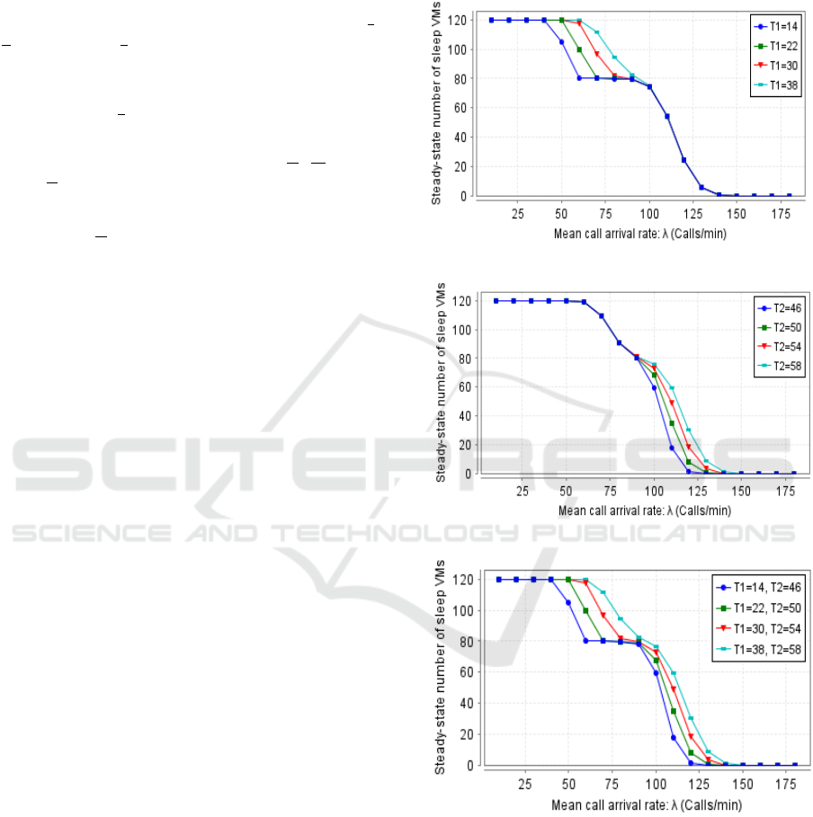
Fig.3 shows the steady-state number of sleep VMs
depending on the hysteresis deactivating thresholds
(T
1
and T
2
) and the traffic load λ. The correspond-
ing reward function to this measure is L
′
, presented in
Eq.10.
We can first remark that all curves are decreasing
because when the arrival of calls increases, VMs pass
from sleep mode to an activated mode to serve calls,
and therefore the number of sleep VMs decreases. In
Fig.3(a), we can observe that the highest curve cor-
responds to the highest value of T
1
. This result is
explained by the fact that when we increase T
1
(be-
comes near to V m
1
), the second level will close fre-
quently, and therefore VMs of the second level fre-
quently pass to the sleep mode. The same results can
be seen through Fig.3(b) when varying T
2
. In Fig.3(c),
we illustrate the mean number of sleep VMs when we
vary T
1
and T
2
. We can observe that the highest curve
is related to the highest values of T
1
and T
2
, which
confirms the results of Fig.3(a) and Fig.3(b).
(a) Varying T
1
.
(b) Varying T
2
.
(c) Varying T
1
and T
2
.
Figure 3: Steady-state number of sleep VMs.
In order to evaluate the steady-state energy con-
sumption in BBU
1
and in BBU
2
by considering dif-
ferent traffic loads, we vary the arrival rate λ of calls
from 10 to 180 calls/min. The corresponding reward
function to these measures are E
′
1
for BBU
1
(see Eq.7)
and E
′
2
for BBU
2
(see Eq.8).
ENASE 2024 - 19th International Conference on Evaluation of Novel Approaches to Software Engineering
106
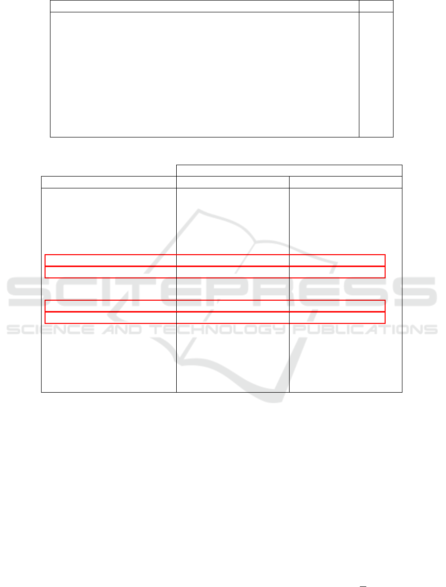
Table 1: Experimental Parameters.
Parameters Value
K: Total number of BBUs. 2
V max: Max number of VMs in a BBU. 100
V m
2
: Hysteresis Level 3 activating threshold. 60
V m
1
: Hysteresis Level 2 activating threshold. 40
T
2
: Hysteresis Level 3 deactivating threshold. 56
T
1
: Hysteresis Level 2 deactivating threshold. 36
1/µ: Mean VM holding time (per minute). 1
E
s
: Energy consumption of a sleeping VM(per mJ). 0.2
E
i
: Energy consumption of an idle VM (per mJ). 0.4
E
b
: Energy consumption of a busy VM (per mJ). 0.5
E
a
: Additional energy consumption of a VM caused by activation (per mJ). 2
Table 2: Steady-state energy consumption in each BBU.
Steady-state energy consumption (mJ)
Call arrival rate: λ (calls/min) BBU
1
BBU
2
10.0 28.521550765802747 28.478449234200447
20.0 29.022981186839626 28.977018814554246
30.0 29.52356702449307 29.476432992294825
40.0 30.023902006144166 29.976125945301177
50.0 30.550625554609844 30.502443296489755
60.0 32.77501023996112 32.72654758056934
70.0 42.53185589385637 42.48318793333326
80.0 45.26724652233278 45.21842171268469
90.0 40.17329401118137 40.12434544337346
100.0 47.250198654799775 47.20114993720736
110.0 67.23262000827796 67.18348857666923
120.0 71.25853230740609 71.20933140571053
130.0 57.790673358614654 57.74141328345368
140.0 49.39830475913209 49.34899371437636
150.0 47.79158282943648 47.74222902769638
160.0 48.04006386928369 47.99069960088592
170.0 48.5055002528775 48.45631940730138
180.0 48.931289400383555 48.882897731887205
It can be observable through Table 2 that when
λ does not exceed 60 calls, the energy consumption
increases slightly in each BBU. This is expected be-
cause only the first level of VMs in two BBUs is acti-
vated to accept calls. However, the remaining two lev-
els are deactivated because they are not needed. When
λ = 70, the energy consumption shows a remarkable
increase; this is explained by the energy consumption
due to the opening of the second level of VMs (see
the first two boxes: λ = 70 and λ = 80). In addition,
each BBU consumes the maximum energy when the
VMs of the third level are activated (see the second
two boxes: λ = 110 and λ = 120).
As observed, the energy consumption of BBU
2
is
slightly lower than the energy consumption of BBU
1
.
This slight difference is explained by the fact that
when the call arrives, it will be assigned to the avail-
able VM in the least-load BBU. By default, when the
current traffic load is the same in the two BBUs, the
first BBU will serve the incoming call. All that shows
that VMHAS schemes ensures the load balancing be-
tween BBUs.
6.2 Performance Comparison Between
VMHAS and VMAS
In this subsection, we perform a comparative analysis
of the steady-state number of idle VMs and the energy
consumption between VMHAS and VMAS schemes.
Fig.4 illustrates the steady-state number of idle
VMs (activated VMs waiting for calls) in VMHAS
and VMAS schemes under different traffic loads.
Their corresponding reward functions are defined re-
spectively by I
′
(see Eq.9) and I
′
(see Eq.12). It can
be seen that the curve of VMAS is always higher
Steady-State Energy Consumption Evaluation in BaseBand Units Pool in Cloud Radio Access Network
107
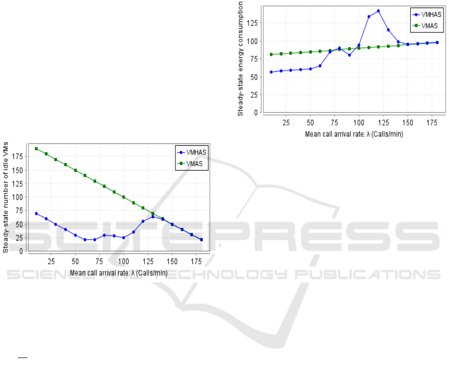
than that of VMHAS and is decreasing because it is a
model that does not consider sleep mode. VMAS is
a scheme in which VMs can be only in two modes:
busy (VMs occupied by calls) or idle; therefore, this
explains the negative slope of its corresponding linear
curve.
For VMHAS, we can see that when the traffic load
in the system does not exceed 60 calls/min, we ob-
tain a decreasing curve because one level of VMs in
two BBUs can support all UEs. The increase of idle
VMs twice (see the two peaks) is caused by the ac-
tivation of VMs of the second (resp. the third level).
Once level three is activated, the two CAC schemes
will have the same number of idle VMs because there
are no VMs in sleep mode in VMHAS. Clearly, the
VMHAS scheme outperforms VMAS because it ad-
justs the number of VMs needed to support the traffic
load in the system.
Figure 4: Steady-state number of idle VMs.
We compare the steady-state energy consumption
between VMHAS and VMAS schemes by consider-
ing different traffic loads. Their corresponding reward
functions are respectively defined by E
′
(see Eq.6)
and E
′
(see Eq.11). It can be observable through Fig.
5 that when the traffic load increases, the mean energy
consumption for both VMHAS and VMAS schemes
increases. This is trivial because when the number
of calls increases, the number of busy VMs increases
too. The VMHAS scheme consumes less energy than
the VMAS scheme due to the utilization of fewer
number of VMs during the low-traffic periods (λ of
calls from 10 to 65 calls per minute). On the other
hand, the VMAS scheme consumes more energy than
expected because all VMs in the two BBUs are always
active. It is also remarkable that in the curve of the
VMHAS scheme, the first peak of energy consump-
tion is shown when the second level of VMs activated;
its energy consumption stays better than the VMAS
scheme. Nevertheless, as the offered traffic increases
(arrival rate λ of calls is from 110 to 120), the second
peak of energy consumption is shown. As a result,
the curve of VMHAS becomes above that of VMAS;
this is justifiable by the additional energy caused by
the activation of 80 VMs. Then, from λ = 150, both
schemes have the same energy consumption because
all VMs are activated.
Figure 5: Steady-state energy consumption.
7 CONCLUSION
In this paper, we have performed a quantitative anal-
ysis of the energy consumption computed over two
schemes named Virtual Machine Hysteresis Alloca-
tion Strategy (VMHAS) and Virtual Machine Allo-
cation Strategy (VMAS) for C-RAN. The VMHAS
scheme consists of switching the idle VMs to sleep
mode to save energy, but the VMAS scheme allocates
VMs without considering the sleep mode. We mod-
eled schemes with MRMs to evaluate measures re-
lated to energy consumption. We used the PRISM
model checker to perform modeling, specification,
and quantification of the steady-state reward measures
of VMHAS and VMAS schemes by checking CSRL
formulas. Results show that the VMHAS scheme per-
forms better than the VMAS scheme in saving en-
ergy under low and medium traffic. Furthermore, it
allowed load balancing between the BBUs. In the fu-
ture, we will extend this work by using Discrete-Time
Markov Decision Processes (MDPs) to enhance the
performance and energy efficiency in the resource al-
location scheme using the hysteresis and the migra-
tion mechanisms.
REFERENCES
Aldaeabool, S. R. and Abbod, M. F. (2017). Reducing
power consumption by dynamic BBUS-RRHS alloca-
tion in C-RAN. In 25th Telecommunication Forum
(TELFOR), pages 1–4. IEEE.
ENASE 2024 - 19th International Conference on Evaluation of Novel Approaches to Software Engineering
108

Alhumaima, R. S., Ahmed, R. K., and Al-Raweshidy, H. S.
(2018). Maximizing the energy efficiency of virtual-
ized C-RAN via optimizing the number of virtual ma-
chines. IEEE Transactions on Green Communications
and Networking, 2(4):992–1001.
Aziz, A., Sanwal, K., Singhal, V., and Brayton, R.
(2000). Model-checking continuous-time markov
chains. ACM Transactions on Computational Logic
(TOCL), 1(1):162–170.
Checko, A., Christiansen, H. L., Yan, Y., Scolari, L., Kar-
daras, G., Berger, M. S., and Dittmann, L. (2014).
Cloud RAN for mobile networks—A technology
overview. IEEE Communications surveys & tutorials,
17(1):405–426.
Duan, L., Zhan, D., and Hohnerlein, J. (2015). Optimiz-
ing cloud data center energy efficiency via dynamic
prediction of CPU idle intervals. In IEEE 8th Interna-
tional Conference on Cloud Computing, pages 985–
988. IEEE.
Feng, M., Mao, S., and Jiang, T. (2017). Base station
ON-OFF switching in 5G wireless networks: Ap-
proaches and challenges. IEEE Wireless Communi-
cations, 24(4):46–54.
Haverkort, B., Cloth, L., Hermanns, H., Katoen, J.-P., and
Baier, C. (2002). Model checking performability
properties. In Proceedings International Conference
on Dependable Systems and Networks, pages 103–
112. IEEE.
Idi, M., Youn
`
es, S., and Robbana, R. (2022). Performance
evaluation of call admission control strategy in cloud
radio access network using formal methods. In Inter-
national Conference on Software and Data Technolo-
gies.
Katoen, J.-P., Khattri, M., and Zapreevt, I. (2005). A
markov reward model checker. In Second Interna-
tional Conference on the Quantitative Evaluation of
Systems (QEST’05), pages 243–244. IEEE.
Kulkarni, V. G. (2016). Modeling and analysis of stochastic
systems. Chapman and Hall/CRC.
Kwiatkowska, M., Norman, G., and Parker, D. (2011).
PRISM 4.0: Verification of probabilistic real-time sys-
tems. In International conference on computer aided
verification, pages 585–591. Springer.
Mai, Z., Chen, Y., Xie, Y., and Chen, G. (2023). An en-
ergy efficiency optimization jointing resource alloca-
tion for delay-aware traffic in fronthaul constrained C-
RAN. Wireless Networks, 29(1):353–368.
Sahu, B. J., Dash, S., Saxena, N., and Roy, A. (2017).
Energy-efficient BBU allocation for green C-RAN.
IEEE Communications Letters, 21(7):1637–1640.
Sigwele, T., Alam, A. S., Pillai, P., and Hu, Y. F. (2017).
Energy-efficient cloud radio access networks by cloud
based workload consolidation for 5G. Journal of Net-
work and Computer Applications, 78:1–8.
Sigwele, T., Pillai, P., and Hu, Y. F. (2015). iTREE: In-
telligent traffic and resource elastic energy scheme for
Cloud-RAN. In 2015 3rd International Conference on
Future Internet of Things and Cloud, pages 282–288.
IEEE.
Yu, N., Song, Z., Du, H., Huang, H., and Jia, X. (2017).
Multi-resource allocation in cloud radio access net-
works. In IEEE International Conference on Com-
munications (ICC), pages 1–6. IEEE.
Zhang, J., Ji, Y., Xu, X., Li, H., Zhao, Y., and Zhang, J.
(2016). Energy efficient baseband unit aggregation in
cloud radio and optical access networks. Journal of
Optical Communications and Networking, 8(11):893–
901.
Steady-State Energy Consumption Evaluation in BaseBand Units Pool in Cloud Radio Access Network
109
