
Ontology to Define Sizing Screw Joints for Mechanical Engineering
Applications
Henrique Priebe
1 a
, Gustavo Roberto Ramos
2 b
and Vinícius Maran
1 c
1
Laboratory of Ubiquitous, Mobile and Applied Computing (LUMAC), Polytechnic School,
Federal University of Santa Maria, Av. Roraima, 1000, Santa Maria, Brazil
2
Group on Mechanics of Materials and Structures (GMEC), Federal University of Santa Maria, Rodovia Taufik Germano,
3013, Cachoeira do Sul, Brazil
Keywords:
Machine Elements, Ontology, Bolts, Bolted Joints.
Abstract:
The sizing of bolted joints is crucial for mechanical projects that will experience working loads. This requires
careful analysis during the design specification phase, where materials, manufacturing processes, components,
and layout are determined. This analysis is time-consuming since most of it is done manually using analytical
calculations, as there are limited computational tools available. Developing such tools requires a formal repre-
sentation of knowledge that algorithms can process. The purpose of this work is to create a conceptual model,
using ontologies, to represent the information found in specialized literature about bolts and bolted joints.
By doing so, it becomes possible to automate calculations for bolt stiffness and stiffness of joint elements.
The ontology was built following the UPON methodology, which involves extracting domain terms to guide
knowledge modeling. The resulting ontology provides a formal and explicit representation of statically loaded
bolted joints in an axial direction. It also has the capability to answer predetermined competence questions,
indicating that it can be used by software applications to process information efficiently.
1 INTRODUCTION
Since the Industrial Revolution, the time needed to
develop new technologies and products has been
shorter and shorter. From the mechanization of previ-
ously artisanal processes, new methods and philoso-
phies were developed to increase the production
speed, improve the quality of the products and reduce
the costs involved (Silveira, 1998).
The common point of the different recent de-
sign methodologies are the stages that compose them.
These can be generalized as follows: an initial phase
of identifying needs, a phase of collecting informa-
tion and defining the problem, a phase of specifying
the project and sizing components, a phase of build-
ing the prototype and, finally, product validation to
start production (Silveira, 1998). During the speci-
fication of a mechanical project, screws and fasten-
ers are recurrent and of great importance components,
available in a numerous variety for the most diverse
applications. Likewise, there are abundant types of
a
https://orcid.org/0000-0001-9678-9613
b
https://orcid.org/0000-0002-3914-1826
c
https://orcid.org/0000-0003-1916-8893
bolted joints available, due to the constant evolution
of this area (Budynas and Nisbett, 2007). The cor-
rect sizing and selection of bolts in a bolted joint is of
paramount importance to avoid failures in a project,
especially when it is subject to significant loads and
stresses (Norton, 2010). There are few tools for anal-
ysis or aid in the design of bolted joints that use an-
alytical methods. For the development of computa-
tional tools in this context, it is of great importance
the adequate modeling of the information, as well as
the modular expansion of the database (Kogalovsky
and Kalinichenko, 2009). This modeling may aim
at building ontologies, formal and explicit represen-
tations of knowledge in a given domain, so that it is
understood and processed by software (Antoniou and
Harmelen, 2009). Thus, the present work aimed to
conceptually model, through a representation using
ontologies, the information found in specialized lit-
erature (Budynas and Nisbett, 2007) (Collins et al.,
2009), referring to screws and bolted joints statically
loaded under tension, so that it is possible to automate
the calculation processes for their analysis.
The paper is structured as follows: Section 2
presents a bibliographical review referring to bolts
Priebe, H., Ramos, G. and Maran, V.
Ontology to Define Sizing Screw Joints for Mechanical Engineering Applications.
DOI: 10.5220/0012675600003690
Paper published under CC license (CC BY-NC-ND 4.0)
In Proceedings of the 26th International Conference on Enterprise Information Systems (ICEIS 2024) - Volume 2, pages 53-64
ISBN: 978-989-758-692-7; ISSN: 2184-4992
Proceedings Copyright © 2024 by SCITEPRESS – Science and Technology Publications, Lda.
53
and bolted joints, as well as conceptual modeling
and information systems, and some work related to
machine elements and ontologies. In Section 3, the
methodology used for the development of the work is
presented, as well as partial results obtained through
its application. In Section 4, the results regarding on-
tology tests are described and discussed. Finally, Sec-
tion 5 presents conclusions and possibilities for ex-
pansion of this work.
2 DOMAIN BACKGROUND
The product design methodology is defined, accord-
ing to (Albuquerque et al., 2020), as the study of
methods applicable to designs. It is a set of sys-
tematic and methodological procedures, adaptable to
problems in general, which aim to obtain a suitable
product to meet certain needs. These procedures
are grouped into phases, which vary among the var-
ious authors who address the topic, but in general
maintain the meaning (Silveira, 1998). According to
(Nicholas and Steyn, 2020) the phases of a project
consist of: requirements, problem statement, solu-
tion generation, evaluation and testing. Similarly,
(Omelyanenko et al., 2021) presents the phases of the
project life cycle such as conception, planning, execu-
tion, monitoring and control, closing. (Collins et al.,
2009) subdivides the design activity into four stages:
preliminary design, intermediate design, detail design
and development, and field service. It is important for
designers to have technical knowledge regarding the
machine elements necessary for a correct sizing and
selection of these (Norton, 2010). Thus, the analysis
of the components of a mechanical project must be
carried out individually and, as these are usually con-
nected, it is also necessary to evaluate the influence
of each component on the system as a whole (Budy-
nas and Nisbett, 2007). Likewise, the connections be-
tween components must be studied in order to choose
an appropriate joining method, so that problems of
geometric discontinuities and points of stress concen-
tration are avoided or reduced (Collins et al., 2009).
Consequently, there are several analytical and com-
putational methods available for the analysis of joints,
among them, screw joints (Bruzzone et al., 2019).
2.1 Screws and Screwed Joints in
Mechanical Engineering
Screws can be divided into two types according to
their application: power screws and fixing screws.
Those of the first group, also called linear actuators,
are used to convert angular movement into linear,
while those of the second group are mainly used in
non-permanent joints (Collins et al., 2009). However,
due to the defined objectives, the approach of this
work is directed to fastener-type screws. According to
(Norton, 2010), there are different ways of classifying
fasteners: according to the intended use (bolts, ma-
chine screws or studs); by the type of thread (screws,
cutters, self-drilling); according to the type of head
(hexagonal, slotted, Phillips) and according to resis-
tance (due to materials and manufacturing processes).
The distinction between bolts and machine screws is
semantic only, as the same fastener can be used in
conjunction with a nut or threaded into a hole. Stud,
on the other hand, are characterized by the absence of
a head, having threads at both ends (Norton, 2010).
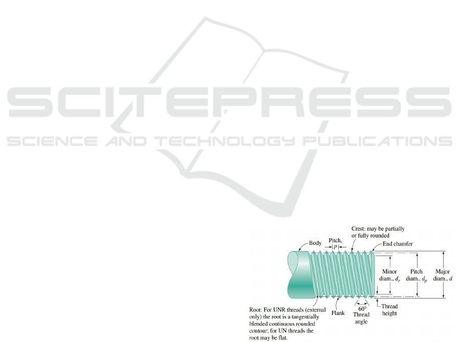
Threaded fasteners have certain terminologies and
definitions in common, used to characterize them and
help in the calculation of their properties. The first
of these is the pitch (p), defined as the axial distance
between corresponding points on adjacent threads,
or the number of threads per inch, in English units
(Collins et al., 2009). Then we have major diameter
(d) as the largest diameter of the thread, minor diam-
eter (d
r
) as the smallest diameter (root) and primitive
diameter (d
p
) being a theoretical diameter between
the largest and smallest (Budynas and Nisbett, 2007).
Another definition is the lead (l), corresponding to
the axial displacement of a nut after one revolution.
This is equal to one pitch for single threads, equiv-
alent to twice the pitch for double threads, or three
times the pitch for triple threads (multi-entry threads)
(Norton, 2010). By default, threads are made clock-
wise (unless otherwise specified), so the bolt advances
through the nut when turned in this direction and re-
tracts when turned in the opposite direction (Budynas
and Nisbett, 2007). Figure 1 illustrates some of these
definitions for a single-thread screw.
Figure 1: Screw thread terminology. Adapted from (Collins
et al., 2009).
After the Second World War, there was a need to
standardize the shapes of the threads, and the series
UNS (Unified National Standard) emerged through
the countries England, Canada and the United States
ICEIS 2024 - 26th International Conference on Enterprise Information Systems
54

of America, as well as the European standard through
ISO (International Organization for Standardization)
(Norton, 2010). UNS series threads have inch dimen-
sions and are designated by “UN”, while ISO stan-
dard threads use the metric system and are designated
by “M”. These designations receive, respectively, the
letters “R” and “S” at the end, when you want to
specify a rounded root (Collins et al., 2009).
2.2 Shigley’s Method for Analysis of
Bolted Joints
The main function of a screw is to keep two or more
elements together, for this purpose it is pulled through
the application of torque to the nut, producing a reten-
tion force called preload, which guarantees the union
of the elements as long as the external force does not
cause their separation (Budynas and Nisbett, 2007).
According to (Norton, 2010), in static assemblies a
preload of 90% of the proof load can be imposed on
the bolt, while in joints subject to dynamic loads the
preload can exceed 75%. According to (Budynas and
Nisbett, 2007), in permanent connections a preload of
90% is recommended and, in non-permanent joints in
which the fasteners will be reused, a preload of 75%.
The importance of preload is related to the elastic be-
havior of the bolted joint, whose components can be
modeled as linear springs (Collins et al., 2009). For
springs in series, the total spring constant can be cal-
culated by:
1
k
=
1
k
1
+
1
k
2
+
1
k
3
+ ...+
1
k
n
, (1)
where n is the number of springs. Thus, according
to (Norton, 2010), for a screw of diameter d with a
length of the threaded portion of the grip l
t
, used in
a joint with a clamped zone of length l, the elastic
constant is given by:
k
b
=
A
t
A
b
A
b
l
t
+ A
t
l
s
E
b
, (2)
where l
s
= l − l
t
is the length of the unthreaded part
of the bolt, A
t
is the tensile stress area of the fas-
tener, A
b
is the total cross-sectional area, and E
b
is the
Young’s modulus of the bolt. To obtain the stiffness
of the elements (which are being compressed) there
are different analytical methods that are distinguished
mainly by the format attributed to the stress distribu-
tion along the elements. According to (Budynas and
Nisbett, 2007), one of the best known and widely used
is the method proposed by Shigley, which considers
the stress distributed in the form of a truncated cone
with angle α = 30º, as shown in Figure 2. When sub-
jected to a compressive force P, a certain element of
thickness dx of the cone (Figure 2(b)) suffers a con-
traction given by:
dδ =
Pdx
EA
, (3)
where E is the material’s Young’s modulus and A is
the area of the element, given by:
A = π
x tan α +
D+d
2
x tan α +
D−d
2
. (4)
Figure 2: Representation of the stress distribution by a trun-
cated hollow cone. Adapted from (Budynas and Nisbett,
2007).
Thus, the total contraction of the element is ob-
tained by substituting the result of the area in the
Equation 3 and integrating, which results in:
δ =
P
πEd tan α
ln
(2t tan α + D − d)(D + d)
(2t tan α + D + d)(D − d)
. (5)
Therefore, as the stiffness of the cone is given by
k = P/δ, substituting α = 30° this will be:
k =
0.5774πEd
ln
(1.155t + D − d)(D + d)
(1.155t + D + d)(D − d)
. (6)
The total elastic constant of the elements re-
quested in the union (k
m
) is obtained by solving Equa-
tion 6 separately for each frustum of cone and sub-
stituting the results in Equation 1, to which the in-
dex m is added in this case. If the joint has back-to-
back symmetrical frusta and elements with the same
value for E, the total elastic constant will be given by
k
m
= k/2 (Budynas and Nisbett, 2007). Considering
an external tensile load P (Figure 3), a portion P
b
of
this will act on the screw and the remaining P
m
on
the elements being compressed. As shown in Figure
3, each side of the junction receives half the load P,
resulting in P/2.
It can be shown that the portion P
b
of the external
load applied to the joint is given by:
P
b
=
k
b
P
k
b
+ k
m
= CP, (7)
where C =
kb
kb+km
is defined as the joint stiffness con-
stant. Therefore, the portion P
m
is:
P
m
= (1 − C)P. (8)
Ontology to Define Sizing Screw Joints for Mechanical Engineering Applications
55

Figure 3: Bolted joint under external tensile load. Adapted
from (Norton, 2010).
Thus, the resulting load on the bolt is obtained
through:
F
b
= P
b
+ F
i
, (9)
where F
i
is the preload. Analogously, the resulting
load on the elements is obtained from
F
m
= P
m
− F
i
, F
m
< 0. (10)
With this, (Budynas and Nisbett, 2007) establish a
load factor n, which guarantees that the stress on the
bolt is less than its proof strength as long as n > 1.
This factor is given by
n =
S
p
A
t
− F
i
CP
, (11)
where S
p
is the bolt proof strength. Analogously, the
authors established a safety factor against screw yield-
ing (n
p
), obtained through
n
p
=
S
p
A
t
CP + F
i
. (12)
According to (Norton, 2010), it is also possible to
find a safety factor against failure by separation N
sep
.
This is given by
N
sep
=
F
i
P(1 − C)
. (13)
From the presented equations, the point of in-
terest is centered on the determination of the stiff-
ness of the elements requested in the union (k
m
),
using the Shigley method. According to (Brown
et al., 2008), despite the particularities, Shigley’s ap-
proach considering a truncated cone for stress distri-
bution along compressed elements has been success-
fully used since 1960 for the design and analysis of
bolted joints with axisymmetric geometry.
2.3 Ontology Methodologies
For the construction of ontologies, several method-
ologies were developed. Among the first publications
in this context are those by (Guarino, 1997) and (Noy
and McGuinness, 2001), in which sequential and sys-
tematic actions were proposed to obtain ontologies
with good representativeness of modeled knowledge.
Afterwards, other methods were also developed, in-
cluding UPON (Unified Process for ONtology) by
(De Nicola et al., 2009) and SABiO (Systematic Ap-
proach for Building Ontologies) by (Falbo, 2014),
seeking solutions for problems of previous methods
or aiming to meet more specific needs. According
to (Maran et al., 2018), there is not a single suitable
methodology for all situations, as all of them present
formalisms to be followed, with the choice depend-
ing on the objectives and the domain to be repre-
sented. Thus, the UPON developed by (De Nicola
et al., 2009) was chosen, due to the clarity of the steps
elucidated with examples, the possibility of evaluat-
ing the partial results during the construction and rel-
evance of the work. This methodology was based on
the Unified Software Development Process, or Uni-
fied Process (UP), a consolidated standard due to its
wide use in software engineering (De Nicola et al.,
2009). Thus, it consists of five general workflows: (a)
Requirements workflow, (b) Analysis workflow, (c)
Design workflow, (d) Implementation workflow and
(e) Test workflow.
2.4 Related Work
As already mentioned, there are few works report-
ing the development of tools for analysis of bolted
joints that use analytical calculation techniques. The
closest found was from (Godden, 2015), in which a
computer program called FORTRESS (Fastener Op-
timization Research Technologies Rapid Efficient Se-
lection Software) was developed to identify and se-
lect the most efficient threaded fasteners for the joint
selected by the user, based on the information pro-
vided by the user. (Sanli, 2017) developed analy-
sis methods through the creation of Artificial Neural
Networks. In these cases, as the field of application
of the tools was Aeronautics, several analyzes were
needed in a short period of time, aiming at the max-
imum reduction of mass of the joints. In both, the
conceptual modeling of the information resulted in
a large database, which mainly kept results of previ-
ous analyzes, which were used for training the devel-
oped Artificial Neural Networks. However, despite an
extensive literature search, no papers were found re-
porting the use of ontologies to represent knowledge
related to bolts and bolted joints. However, ontolo-
gies are already used in related areas, as, for exam-
ple, in the work of (Chang et al., 2017), in which
an ontology was proposed to assist in the planning
of a cold forging process of flanged nuts. More gen-
erally, (Gupta and Gurumoorthy, 2021) developed an
ontology that allows the continuous exchange of in-
formation at the semantic level, during all stages of
ICEIS 2024 - 26th International Conference on Enterprise Information Systems
56

the life cycle of an industrial product. In the area of
systems design, (Liang and Paredis, 2004) developed
an ontology to formally represent concepts of interac-
tion ports between a component and the surrounding
environment. These ports are component interfaces
through which iterations such as signal, energy, or
material exchanges must take place. Thus, expanding
the ontology to include LEGO components, the au-
thors demonstrated that it is possible, among others,
to refine the design and verify compatibility.
Also in the area of designs, but aiming at col-
laborative development, (Tran and Lobov, 2020) de-
veloped an ontology to represent geometric shapes
and functionalities of CAD (Computer Aided Design)
software, aiming at the automated generation of 3D
geometries. Thus, from instructions in Python to gen-
erate a shape, the knowledge base (ontology) is con-
sulted, with the information returned about the shape
and the resources to create it transmitted to the soft-
ware Siemens NX and Knowledge Fusion, responsi-
ble for generating it. Thus, a manual water pump was
created to demonstrate the potential of the developed
system.
3 THE DEVELOPMENT
PROCESS
3.1 The Requirements Workflow
The domain of interest was defined as "Bolts and
bolted joints", with the scope restricted to joints with
axisymmetric geometry, statically loaded under ten-
sion. Furthermore, for reasons of simplification, all
elements of the bolted joint were considered to be
composed of the same material, including any wash-
ers used. As a business objective or motivating sce-
nario, the main reasons for creating the ontology
should be listed. At the time of this work these were:
(i) Formally represent the knowledge of the domain
of interest, enabling queries and inferences; (ii) En-
able the automation of bolted joints analysis calcula-
tions by applications that may use the ontology. The
writing of one or more storyboards aims to describe
a sequence of actions or activities that may occur in
a particular scenario, involving the constructed ontol-
ogy (De Nicola et al., 2009). Thus, considering that
the ontology was hypothetically integrated into an ap-
plication, two situations were described:
• “The user, through an application, makes a re-
quest for analysis of a junction to the server. The
server processes the request by querying the on-
tology, and returns the types of bolted joints avail-
able for analysis.”;
• “The user selects a type of joint, assigns values
to the variables (external load, element thickness,
number of bolts, bolt length, diameter, among oth-
ers) necessary for the calculations and requests
the server for the analysis. The server, through
pre-defined algorithms and queries to the ontol-
ogy, performs the calculations and returns the re-
sults of the analysis to the user”.
The Application Lexicon (AL) consists of a set of
terms extracted from specific application documents,
using the storyboards as a reference to prioritize the
terms to be extracted. The elaborated AL was con-
cluded with a total of 80 terms, mainly extracted from
the specialized literature referenced in Section 2.1.
The competency questions must be answered by the
ontology during the Test Workflow, to assess its cov-
erage in relation to the domain and its depth in rela-
tion to the (De Nicola et al., 2009) concepts. Thus, the
following questions were listed, which refer mainly
to the relationships that the components of a bolted
joint have with each other: CQ.1 What are the main
components of a bolted joint? CQ2. What types of
threads can a screw have? CQ3. What type of screw
should be used when one of the joint elements has a
threaded hole? At the end of this workflow, the LA
and the competence questions are validated, verify-
ing whether the collected terms represent the domain
and whether the competence questions are appropri-
ate. Therefore, for the present work, some iterations
were necessary, aiming to reassess the domain of in-
terest and scope, as well as to include new terms in
the LA and adapt the competence issues to the capa-
bilities of the intended ontology.
3.2 Analysis Workflow
According to (De Nicola et al., 2009), the first stage
of this workflow is the creation of a Domain Lexi-
con (DL), through the collection of terms in docu-
mented resources related to the considered scope (ar-
ticles, technical reports, manuals or other ontologies).
As this task can be aided by text mining tools, a script
in Python was developed again to collect and manage
these terms. In order to collect terms directly from
documents, the library PDFMiner
1
was used in the
script to extract only the text from files in PDF, and
the library Yake
2
to collect keywords from extracted
text. At the end of the extraction, 27 versions of the
.txt file were created by the script in Python, with the
last version containing a total of 288 terms, extracted
1
Available at: https://pypi.org/project/pdfminer/
2
Available at: https://github.com/LIAAD/yake
Ontology to Define Sizing Screw Joints for Mechanical Engineering Applications
57

mainly from scientific articles and books related to the
considered domain. The Table 1 shows part of these
terms that make up the Domain Lexicon.
Table 1: Part of the terms that make up the Domain Lexi-
con.
Axial external force Factor of safety Member stiffness Stress
Bolt Fasteners Nut Tapped thread joint
Bolt tension Fine pitch thread Plain washer Thread
Bolted joint Geometry Regular nut Threaded connection
Clamped member Hexagonal nut Results Tool
Coarse pitch thread ISO thread SAE specifications UNC thread
Connection system Joint Screw UNF thread
Design Loads Simplified method UNS thread
Disassembly Material Size Variables
Element Mechanical properties Software Washers
The next step in this workflow consists of creating
the Reference Lexicon (LR), through the intersection
between the LA and the LD (terms common to both
lexicons). In addition, unique terms can be added to
each of the lexicons, which are considered important
by the Domain Expert (De Nicola et al., 2009). To
help with the task of identifying terms common to LA
and LD, another script was created in Python, with
the options to compare the two lexicons, as well as to
allow manual entry of terms. With the intersection of
the LA and LD terms, as well as adding some terms
manually, the LR was completed after creating seven
versions in .txt format and with a total of 58 terms.
The creation and intersection of lexicons aims to
identify the most important concepts of the consid-
ered domain, which will serve as a basis for building
the ontology, mainly in the form of classes and prop-
erties. Therefore, it is important that these terms are
formally defined, associating definitions from several
sources for each (De Nicola et al., 2009) term. Thus,
the next stage of this workflow dealt with the elabora-
tion of a Reference Glossary (GR), where a definition
was associated with each term. Table 2 shows a frac-
tion set of the GR. This workflow ends with the vali-
dation of the GR by verifying the scope of the defined
terms. Thus, there was a need to perform some iter-
ations, returning to LA and LD to find and add new
terms, as well as manually adding important terms to
LR, present in only one of the predecessor lexicons.
3.3 The Project Workflow
According to (De Nicola et al., 2009), this workflow
starts with the modeling of concepts, in which they
are organized into three primary categories and some
complementary categories. The primary categories
are: business actor (business actor), business object
(business object) and business process (business pro-
cess). In the business actor category, elements capa-
ble of activating, executing or monitoring a process
are identified. Entities in which a process operates are
allocated in a business object. As a business process,
activities or operations that aim to achieve a defined
objective (De Nicola et al., 2009) are classified. For
this work, the concepts present in the Table 3 were
listed for the primary categories, mainly coming from
the GR. As a business actor, a user of a possible appli-
cation that uses the knowledge modeled in the ontol-
ogy was identified. In a business object, entities were
listed that an application would use to request infor-
mation from the ontology or perform calculations. Fi-
nally, in the business process category, activities car-
ried out by the possible application were separated. In
addition to the primary categories, there are comple-
mentary categories, necessary for a rich ontological
representation of the considered domain.
The next step in this workflow deals with mod-
eling concept hierarchies, where formal relationships
begin to be adopted and a hierarchical approach must
be chosen. According to (De Nicola et al., 2009),
there are three usual approaches: from top to bottom,
starting from more general terms towards more spe-
cific ones; from bottom to top, starting with specifics
towards general; and center out, an approach that
combines the previous ones. The last (combined) ap-
proach is considered to be the most efficient because
it starts with the most relevant and informative con-
cepts located in the central area of the domain, creat-
ing generalizations and specifications from these (De
Nicola et al., 2009). With that, a semantic network of
concepts begins to be built, represented by a class dia-
gram to which object properties are also added, which
relate individuals belonging to a class to individuals
of another class (Antoniou and Harmelen, 2009).
Using the combined approach, the hierarchy of
concepts for the present work was initiated by a class
Joint and the respective subclasses TappedThread-
Joint and BoltedJoint, representing the categories of
joints with threaded hole and bolted joints. In ad-
dition, a joint must be composed of elements and
bolts, as well as nuts and washers, making it neces-
sary to use the object properties hasElement, hasS-
crewFastener and hasWasher, relating the class Joint
to the respective classes of these components. Sub-
classes of a superclass can also have object proper-
ties, so TappedThreadJoint has the properties has-
THE_TTJ
3
and hasSHE_TTJ
4
, whereas BoltedJoint
has hasSHE_BJ
5
, so that it is possible to distinguish
which elements each type of joint can contain (with
simple or threaded hole). A property like hasWasher
does not appear in subclasses of Joint as both can have
the same washers. On the other hand, hasNut is a
3
hasThreadedHoleElement_TappedThreadJoint.
4
hasSimpleHoleElement_TappedThreadJoint.
5
hasSimpleHoleElement_BoltedJoint.
ICEIS 2024 - 26th International Conference on Enterprise Information Systems
58

Table 2: Part of the Reference Glossary terms and their definitions.
Term Description
Bolt Is a type of fastener made from metal, that comprises a head at one end, a chamfer at the other, and a shank characterized by an external helical ridge known as a thread.
Bolted joint Demountable joint, made up of screws, nuts and compressed elements, capable of withstanding external loads.
Clamped member Element fixed by bolts in a bolted connection.
Coarse pitch thread Coarse pitch series metric thread.
Elastic modulus It is the quantity that measures the resistance of an object to elastic deformation when a stress is applied.
Element Component of a mechanical system subject to loads and stresses.
Fine pitch thread Fine pitch series metric thread.
Hexagonal nut Nut that has a hexagonal cross-sectional area.
ISO thread Thread with diameters and areas according to the International Organization for Standardization.
Joint Union of two or more elements, held by bolts.
Mechanical properties Properties that influence the material’s reaction to applied loads.
Nut Fastening device consisting of a square or hexagonal block of metal, with a hole in the center, and internal threads that fit the external threads of a screw.
SAE specifications Bolt specifications for SAE grades.
Screw fastener Screws used in non-permanent joints.
Tapped thread joint Demountable joint, made up of screws and compressed elements, in which one of the elements has threaded holes.
Thread A continuous helical ridge formed on the inside or outside of a cylinder.
UNC thread UNS thread of coarse series.
UNF thread UNS thread of fine series.
Washer Small metal, rubber or plastic ring used under a nut or bolt head to distribute pressure when tightened or between two mating surfaces as a spacer or seal.
Young’s modulus Property of the material that inform how easily it can stretch and deform, defined as the ratio of tensile stress to tensile strain.
Table 3: Concepts listed for primary modeling categories.
Business Actors Business Object documents Business Processes
User Available joints Calculation of joint stiffness
Available bolts Calculation of safety factor against bolt yielding
Bolted joint analysis Calculation of safety factor against separation
Joint data Calculation of the bolt stiffness
Safety factor against bolt yielding Calculation of the joint stiffness constant
Safety factor against separation Calculation of the load on the bolt
Screw data Calculation of the load on the elements
Process joint data
Process screw data
Request available bolts
Request available joints
Request bolted joint analysis
Return available bolts
Return available joints
Send joint data
Send screw data
unique property of BoltedJoint because only this type
of joint should contain nut.
To represent the components of a joint, we started
by creating a class Element and subclasses Simple-
HoleElement and ThreadedHoleElement. The Ele-
ment class has the object property hasMechanical-
Property and is related to the Joint class through
the hasElement property. Furthermore, the sub-
class ThreadedHoleElement still has the property
hasThread_Element. Then, the fastening screws were
represented through the ScrewFastener class and its
subclasses Bolt, MachineScrew and Stud, following
the classification according to the intended use (bolt,
machine screw or stud), as discussed by (Norton,
2010). With the exception of the Stud subclass,
the class hierarchy continues after the ScrewFastener
subclasses, aiming to classify the screws also accord-
ing to the head shape. As object properties, the class
ScrewFastener has hasThread_Screw linking it with
the class that represents the threads, and hasSpecifi-
cation which connects it with the class where tech-
nical specifications of screws are hierarchical. Fur-
thermore, ScrewFastener and its subclasses are linked
to Joint and its hierarchy through the properties has-
ScrewFastener, hasMachineScrew, hasBolt and has-
Stud.
A bolted joint can also contain washers with dif-
ferent functionalities, however, for this work only flat
washers were represented, as they have a more ho-
mogeneous geometry and can be considered part of
the joint elements for analytical purposes, when made
of the same material of these (Norton, 2010). The
representation of these washers occurred through the
Washer class, its subclass PlainWasher and the rest
of the hierarchy. The Washer class is linked to the
Joint class via the hasWasher object property. An-
other component that may be included in a bolted
joint is the nut, with the function of ensuring the union
together with the bolt when none of the elements has
a threaded hole. This component was represented us-
ing the Nut class, its subclass HexagonalNut and the
rest of the hierarchy. The Nut class has the prop-
erty hasThread_Nut linking it to the class that rep-
resents the threads, and is connected to the Bolted-
Joint class through the hasNut property. Although
there are several types of nuts, we chose to represent
only the hexagonal ones. In addition to the classes
already mentioned, concepts responsible for specifi-
cations, properties and particularities of the bolted
joint elements were also represented, with emphasis
on the Thread class and its subclasses UNSThread and
ISOThread, which characterize the two thread form
standards adopted since the end of World War II (Nor-
ton, 2010). Thus, the complete hierarchy of all classes
and their respective object properties are presented in
the diagram of Figure 4, where the generic class Thing
appears in the center, uniting all classes to the same
primary root. The validation of the semantic network
required at the end of this workflow was carried out
by analyzing the first versions of the diagram in Fig-
ure 4 regarding the scope of the considered domain.
In these analyses, it was noticed the need to include
classes to represent individuals from tabulated infor-
mation in the literature, mainly from (Budynas and
Nisbett, 2007) and (Norton, 2010). Thus, some itera-
tions were necessary, going back from writing story-
boards, passing through LA and LD, resulting in new
Ontology to Define Sizing Screw Joints for Mechanical Engineering Applications
59

terms in GR, which would become new classes in the
diagram. Examples are UNCThread, SAESpecifica-
tions, MetricWasher, among others.
3.4 The Implementation Workflow
This workflow consists of coding the ontology in a
formal language, with good expressiveness and ac-
ceptance by the community, also considering the as-
sociated computational complexity (De Nicola et al.,
2009). Thus, for this work, the OWL-DL language
was chosen, capable of supporting adequate expres-
siveness and even evolving to OWL Full depending
on the complexity of the representations used (Hit-
zler, 2021). To create the ontology, the Protégé (Noy
et al., 2003) tool was used, a free software with an
open architecture, which allows the development of
new functionalities by the users themselves. In this,
the ontology is encoded and converted into an output
file with the extension .owl, which can be consulted
and manipulated by algorithms and libraries of differ-
ent languages.
3.5 The Test Workflow
According to (De Nicola et al., 2009), in this work-
flow the ontology is evaluated in terms of four dif-
ferent aspects: syntactic, semantic, pragmatic and so-
cial quality. The first three can be measured during
and soon after the construction of the ontology, while
the last one can only be estimated after a certain time
from its publication. Thus, the consequences of this
workflow are shown in the Evaluation Section of this
work.
4 EVALUATION
The UPON methodology implementation workflow,
applied to this work, ended up resulting in an ontol-
ogy with the following metrics: 40 classes, 19 object
properties, 44 data type properties and 379 individu-
als. In addition to the metrics, an ontology needs to be
evaluated for the aspects already highlighted earlier
(Section 3.5). Therefore, the syntactic quality mea-
sures the formality and the way the ontology is cre-
ated, which according to (De Nicola et al., 2009), is
already verified in the implementation workflow. In
the case of the present work, as the creation was car-
ried out using specific software (Protégé), the syntac-
tic quality can be considered sufficient to validate this
aspect. The semantic quality is assessed by check-
ing the consistency of the ontology, verifying the cor-
rect modeling of the concepts, so that there are no (De
Nicola et al., 2009) contradictions. This activity can
be aided by an inference engine (IE), or Reasoner,
which in addition to checking consistency, can also
reclassify the ontology, changing the hierarchy of el-
ements if necessary (Horridge et al., 2004).
Protégé, in its version 5.5.0 brings the IE HermiT
in version 1.4.3.456. Thus, during the construction of
the present ontology, the first executions of the IE re-
sulted in the detection of some errors, mainly arising
from the non-disjunction between the classes. How-
ever, after correcting these, no other problems were
identified. The pragmatic quality is related to the
evaluation of three characteristics of the ontology: fi-
delity, relevance and completeness. The first can be
validated by checking the references used to create the
lexicons and define the terms in the reference glos-
sary. Relevance and completeness can be evaluated
together, verifying the correct application of the on-
tology and meeting the objectives listed in the first
workflow (De Nicola et al., 2009). As for fidelity,
both the terms in LA, LD and LR, and the definitions
shown in the GR, were extracted from scientific arti-
cles cited in the Bibliographic Review of this work, as
well as from the textbooks (Collins et al., 2009), (Bu-
dynas and Nisbett, 2007) and (Norton, 2010), mainly.
In addition, efforts were made during development
to prioritize terms and definitions identified as com-
mon to more than one reference, ensuring greater fi-
delity in the representation of the considered domain.
The relevance and completeness characteristics can
be evaluated by checking coverage and by answering
the competence questions, using the ontology con-
tent (De Nicola et al., 2009). As for the coverage (or
range) of this ontology, analyzing the diagram in Fig-
ure 4, it is possible to see that most of the concepts
related to bolts and bolted joints were represented.
In addition, the classes TypeOfBoltHead and TypeOf-
ScrewHead, for example, which specify together with
their subclasses types of head of bolts and machine
screws, cover concepts that are rarely used in analysis
of bolted joints. However, they were included in the
ontology to extend the scope, bringing tabulated data
related to these particularities.
4.1 Analysis Related to Competence
Questions
The competence questions listed in the requirements
workflow must be answered by consulting the on-
tology, using, for example, the language SPARQL
6
,
adopted for this work. These queries can be exe-
cuted in the SPARQL Query tab of Protégé together
6
Available at: https://www.w3.org/TR/rdf -sparql-
query/
ICEIS 2024 - 26th International Conference on Enterprise Information Systems
60
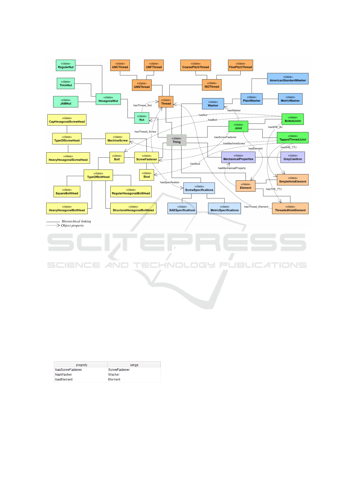
Figure 4: Hierarchy of all ontology object classes and properties.
with standard prefixes, receiving the name of a refer-
ence class and possibly some parameter to filter the
results. Thus, for the first competence question that
says: “What are the main components of a bolted
joint”, the query shown in Figure 1 was elaborated.
This can be read as: “Select distinctly property and
scope when property is of type object property and
has as domain the element Joint, also returning the re-
spective classes of the scope of each property.”. This
results in the table shown in Figure 5.
1 SELECT DISTINCT ? p r o p e r t y ? r an g e
2 WHERE {
3 { ? p r o p e r t y r d f : t y p e owl : O b j e c t P r o p e r t y }
4 ? p r o p e r t y r d f s : domain b d j t : J o i n t .
5 ? p r o p e r t y r d f s : r a n g e ? r a n g e .
6 }
Listing 1: Consultation for the first question of competence.
Figure 5: Query results for the first competency question.
The results of Figure 5 show the object proper-
ties of the class Joint and the respective classes in
the scope of each property, which answers the first
competence question saying that screws, washers and
elements are the main components of a bolted joint.
Although on certain occasions it is possible to con-
sider the washers as part of the element for analysis
purposes, they can be present in any type of joint, in-
dicating their importance. For the second competency
question: "What types of threads can a screw have?",
the Figure query 2 was developed, which reads as:
“Select distinctly property, scope, subclass and “sub-
subclasse” when the property is of the object property
type and has the ScrewFastener element as domain,
also returning the respective classes of the scope of
each property, filtering the properties that have the
term “thread”. Also return the subclasses of each
class in the domain and the subclasses of each sub-
class.”. Thus, this results in the table in Figure 6.
1 SELECT DISTINCT ? p r o p e r t y ? r an g e
2 ? s u b c l a s s ? s u b s u b c l a s s
3 WHERE {
4 { ? p r o p e r t y r d f : t y p e owl : O b j e c t P r o p e r t y }
5 ? p r o p e r t y r d f s : domain b d j t : S c r e w F a s t e n e r .
6 ? p r o p e r t y r d f s : r a n g e ? r a n g e .
7 FILTER REGEX( s t r ( ? p r o p e r t y ) , " t h r e a d " , " i " )
8 {
9 ? s u b c l a s s r d f s : s u b Cl a s s O f ? ra n g e
10 FILTER ( ? s u b c l a s s != ? ra n ge )
11 }
12 {
13 ? s u b s u b c l a s s r d f s : s u b C l a ss O f ? s u b c l a s s
14 FILTER ( ? s u b s u b c l a s s ! = ? s u b c l a s s )
15 }
Listing 2: Consultation for the second question of
competence.
Ontology to Define Sizing Screw Joints for Mechanical Engineering Applications
61

Figure 6: Query results for the second competency ques-
tion.
The table in Figure 6 displays the object prop-
erty (hasThread_Screw) of the class ScrewFastener,
as well as the class (Thread) in the scope of this prop-
erty and their hierarchy in the “subclass” and “sub-
subclass” columns. Thus, it shows that the types of
thread that a screw can have, according to the ontol-
ogy, are: coarse-pitch and fine-pitch ISO, as well as
coarse-pitch UNS (UNC) and fine-pitch (UNF), an-
swering the second question of competence. Finally,
the third competency question asks: “What type of
screw should be used when one of the joint elements
has a threaded hole?”. For this, the query in Figure
3 was elaborated, read as: “Select distinctly property
and scope when property is of type object property
and has as domain the element TappedThreadJoint,
returning also the respective classes of the scope of
each property, requesting the superclasses of each
class of the scope, filtering the classes whose super-
classes have the term “screw”. The result of this is
shown in Figure 7.
1 SELECT DISTINCT ? p r o p e r t y ? r a n g e
2 WHERE {
3 { ? p r o p e r t y r d f : t y p e owl : O b j e c t P r o p e r t y
}
4 ? p r o p e r t y r d f s : domain b d j t :
T a p p e d T h r e a d J o i n t .
5 ? p r o p e r t y r d f s : r a n g e ? r a n g e .
6 ? r a n g e r d f s : s u b C l a s s O f ? s u b c l a s s o f .
7 FILTER REGEX( s t r ( ? s u b c l a s s o f ) , " s c r e w " ,
" i " )
8 }
Listing 3: Consultation for the third question of
competence.
Figure 7: Query results for the third competency question.
The results of Figure 7 present the object proper-
ties of the class TappedThreadJoint and the respective
classes in the scope of each property that belong to the
superclass ScrewFastener, as the interest is centered
only on the screws. Thus, the third competency ques-
tion is answered showing that machine screws and
studs should be used when the joint has a threaded
hole element.
4.2 Evaluation in a Sample Application
To assist in the evaluation of relevance and complete-
ness, as well as to verify the possibility of automating
the calculations for the analysis of bolted joints, an
application was developed in Python capable of al-
lowing some tests to be carried out. This is composed
of three files: app.py responsible for carrying out
the interaction with the user (reading and presenting
data), bolted_joint.py which contains functions to per-
form bolted joint analysis calculations (lengths, stiff-
ness, preload, among others), and query_executor.py
where the interaction with the ontology takes place
through requests in the SPARQL language. The user’s
interaction with the application takes place via the ter-
minal, with the available calculation options shown at
the beginning of the program’s execution. For interac-
tion with the ontology, the file query_executor.py uses
the library RDFLib
7
and contains functions in that a
generic query in SPARQL is concatenated with vari-
ables and property names of data type, according to
the data required for each calculation.
4.3 Study Case and Discussion
To validate the developed application and, conse-
quently, part of the knowledge modeled in the on-
tology, the resolution of Example 8-4 from (Budynas
and Nisbett, 2007) is shown below. Table 4 shows the
comparison of the application results with the exam-
ple results.
Given the above, it can be seen that some re-
sults differ only in terms of the number of decimal
places used, showing that the automation of bolted
joints analysis calculations became possible with the
adopted methodology. Furthermore, the accuracy
achieved by the application indicates that the litera-
ture data were properly modeled and inserted into the
ontology, as well as retrieved correctly. However, as
it was developed with a view to carrying out simple
tests, the application can be greatly expanded, includ-
ing calculation algorithms for more complex configu-
rations of bolted joints.
5 CONCLUSION
This work presents the construction of an ontology
to represent information related to bolted joints, us-
ing most of the steps of the UPON methodology and
developing a simple application to demonstrate the
possibility of automating some calculation processes.
7
Available at: https://rdflib.readthedocs.io/en/stable/
ICEIS 2024 - 26th International Conference on Enterprise Information Systems
62
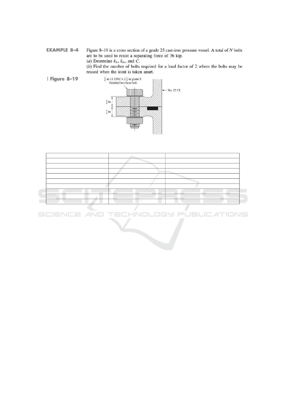
Figure 8: Example used to validate the application in Python (Budynas and Nisbett, 2007).
Table 4: Comparison of results for Example 8-4 of (Budynas and Nisbett, 2007).
Calculation (Budynas and Nisbett, 2007) Python application using the ontology
Screw length (L
T
) 1,50 in 1,50 in
Length of unthreaded portion (l
d
) 0,75 in 0,75 in
Threaded length (l
t
) 0,75 in 0,75 in
Screw stiffness (k
b
) 5,21 Mlbf/in 5,21 Mlbf/in
Stiffness of the elements (k
m
) 8,95 Mlbf/in 8,95 Mlbf/in
Stiffness constant (C) 0,368 0,368
Recommended preload (F
i
) 14,4 kip 14,4 kip
Quantity of screws (N) 6 6
Load factor (n
L
) 2,18 2,18
Thus, analyzing the general objective, it is clear that
this was achieved through the fulfillment of the spe-
cific objectives and their respective consequences.
Methods of analysis of axisymmetric bolted
joints, statically loaded under tension, were identified,
as well as forms of knowledge representation through
ontologies. With that, the information of the men-
tioned joints were hierarchized in classes and con-
verted into an ontology through the UPON method-
ology. This ontology was evaluated in relation to
the aspects foreseen in the methodology and, in ad-
dition, through an application in Python that used
the modeled knowledge to perform some calculations
and present results. The ontology developed, despite
showing to be adequate for the defined objective, con-
tains information about a fraction of the knowledge
referring to bolted joints. However, it can be easily
expanded, including information regarding the analy-
sis of joints loaded under shear and subject to variable
loading, for example. Other types of components may
also be included (socket head bolts, wing nuts, lock
washers, among others.), as well as tabulated data on
various materials used in their manufacture.
This expansion of the ontology could be started by
changing the domain and scope, aiming to cover new
areas of knowledge. As a consequence, the LA would
be added with new terms through the expansion of
the Bibliographic Review of the present work, as well
as the LD with the search for terms in documents of
these new areas. Thus, new terms would be included
in the LR, defined in the GR and incorporated into
the ontology. As with the ontology, the Python ap-
plication developed can be greatly expanded through
the inclusion of new features. For example, queries
to the ontology for knowledge of available compo-
nents and new analysis methods beyond the Shigley
method. Furthermore, it could receive an interface
elaborated through libraries in Python or be integrated
with other technologies, giving rise to countless pos-
sibilities.
ACKNOWLEDGEMENTS
This research is supported by CNPq/MCTI/FNDCT
n. 18/2021 - UNIVERSAL grant n. 405973/2021-
7. The research by Vinícius Maran is supported by
CNPq grant 306356/2020-1 (DT-2).
Ontology to Define Sizing Screw Joints for Mechanical Engineering Applications
63

REFERENCES
Albuquerque, F., Torres, A. S., and Berssaneti, F. T. (2020).
Lean product development and agile project manage-
ment in the construction industry. Revista de Gestão.
Antoniou, G. and Harmelen, F. v. (2009). Web ontology
language: Owl. Handbook on ontologies.
Brown, K. H., Morrow, C. W., Durbin, S., and Baca, A.
(2008). Guideline for bolted joint design and analysis.
Technical report, Sandia National Laboratories.
Bruzzone, F., Delprete, C., and Rosso, C. (2019). A pro-
posal of a unique formula for computing compliance
in bolted joints. Procedia Structural Integrity.
Budynas, R. G. and Nisbett, J. K. (2007). Mechanical En-
gineern Design.
Chang, C. W., Lee, R. S., and Chang, T. W. (2017). De-
velopment of knowledge-expandable ontology-based
expert system for process planning in cold forging of
flange nuts. Procedia engineering, 207:502–507.
Collins, J. A., Busby, H. R., and Staab, G. H. (2009). Me-
chanical design of machine elements and machines: a
failure prevention perspective. John Wiley & Sons.
De Nicola, A., Missikoff, M., and Navigli, R. (2009). A
software engineering approach to ontology building.
Information Systems, 34(2):258–275.
Falbo, R. d. A. (2014). Sabio: Systematic approach for
building ontologies. In ONTO. COM/ODISE@ FOIS.
Godden, N. (2015). Develop an algorithm able to select a
bolted fastener capable to perform at known environ-
mental conditions. Master’s thesis, FDMM.
Guarino, N. (1997). Understanding, building and using on-
tologies. International journal of human-computer
studies, 46(2-3):293–310.
Gupta, R. K. and Gurumoorthy, B. (2021). Feature-based
ontological framework for semantic interoperability in
product development. Adv. Engineering Informatics.
Hitzler, P. (2021). A review of the semantic web field. Com-
munications of the ACM, 64(2):76–83.
Horridge, M., Knublauch, H., Rector, A., Stevens, R., and
Wroe, C. (2004). A practical guide to building owl on-
tologies using the protégé-owl plugin and co-ode tools
edition 1.0. University of Manchester.
Kogalovsky, M. R. and Kalinichenko, L. A. (2009). Con-
ceptual and ontological modeling in information sys-
tems. Programming and Computer Software.
Liang, V.-C. and Paredis, C. J. (2004). A port ontology
for conceptual design of systems. J. Comput. Inf. Sci.
Eng., 4(3):206–217.
Maran, V., Machado, A., Machado, G. M., Augustin, I., and
de Oliveira, J. P. M. (2018). Domain content querying
using ontology-based context-awareness in informa-
tion systems. Data & Knowledge Engineering.
Nicholas, J. M. and Steyn, H. (2020). Project management
for engineering, business and technology. Routledge.
Norton, R. L. (2010). Machine design. Prentice Hall.
Noy, N. F., Crubézy, M., Fergerson, R. W., Knublauch, H.,
Tu, S. W., Vendetti, J., and Musen, M. A. (2003).
Protégé-2000: an open-source ontology-development
and knowledge-acquisition environment. In AMIA.
Annual Symposium proceedings. AMIA Symposium.
Noy, N. F. and McGuinness, D. L. (2001). Ontology devel-
opment 101: A guide to creating your first ontology.
Omelyanenko, V., Braslavska, O., Biloshkurska, N.,
Biloshkurskyi, M., Kliasen, N., and Omelyanenko,
O. (2021). C-engineering based industry 4.0 innova-
tion networks sustainable development. International
Journal of Computer Science and Network Security.
Sanli, T. V. (2017). Development of Artificial Neural Net-
work Based Design Tool for Aircraft Engine Bolted
Flange Connection Subject to Combined Axial and
Moment Load. PhD thesis, MIDDLE E. Tech. Univ.
Silveira, Z. d. C. (1998). Development of a manager sys-
tem for calculation of machine elements for mechani-
cal projects. In Teses.Usp.Br.
Tran, T. A. and Lobov, A. (2020). Ontology-based model
generation to support customizable kbe frameworks.
Procedia Manufacturing, 51:1021–1026.
ICEIS 2024 - 26th International Conference on Enterprise Information Systems
64
