
Comprehensive Traceability Framework for Synchronizing Design UML
Sequence Diagrams with a BPMN Diagram
Aljia Bouzidi
1
, Nahla Haddar
2
and Kais Haddar
3
1
ISIMM, Monastir University, Monastir, Tunisia
2
FSEGS, Sfax University, Sfax, Tunisia
3
FSS, Sfax University, Sfax, Tunisia
Keywords:
Alignment, BPMN, Design Sequence Diagram, Explicit Traceability.
Abstract:
In contemporary software engineering, business process models (BPM) play a crucial role in the development
of information systems (IS). However, a significant discrepancy arises, as only a limited number of systems
align with their intended business processes, resulting in inconsistencies between economic and IS models.
Recognizing this gap, our research introduces an explicit traceability methodology, expanding on a previous
requirements traceability approach. The primary aim is to address the alignment and coevolution of dynamic
viewpoints between software models and BPM. Initially, we establish a unified trace metamodel that encom-
passes elements from Business Process and Model Notation (BPMN) and Unified Modeling Language (UML),
including use cases and design sequence diagrams. This metamodel establishes traceability links among in-
terconnected elements. Following this, we instantiate these metamodels as BPMNTraceISM diagrams. The
feasibility of our traceability method is affirmed through the implementation of a comprehensive graphic ed-
itor designed for the creation and visualization of BPMNTraceISM diagrams. Additionally, we demonstrate
the effectiveness of our approach through testing in a case study.
1 INTRODUCTION
In modern software engineering process methodolo-
gies, the increasing significance of business process
models (BPM) within information systems (IS) de-
velopment cannot be overstated. These models play
a pivotal role in ensuring a seamless alignment be-
tween the information system and the organization’s
business processes. They enhance communication,
streamline requirements analysis, and substantially
contribute to the successful implementation and op-
eration of the information system. Nevertheless, the
prevalent development of these modeling approaches
in isolation often results in a limited synchronization
between them, underscoring the necessity to bridge
this divide for the advancement of the field. Trace-
ability is vital in software development, linking ar-
tifacts to reflect changes across a project. For in-
stance, when requirements change, traceability iden-
tifies affected design artifacts, enhancing project de-
liverable quality. Although constructing such a model
is challenging, it serves as a reference for coherent
traceability links between heterogeneous models, en-
suring integrity. This paper aims to address the dis-
parity between BPM and IS models using a trace-
ability mechanism. The focus remains on pivotal
diagrams representing the Information System, en-
compassing the functional viewpoint through UML
Use Case diagrams and the behavioral aspect de-
picted by Design Sequence diagrams (Specification,
2017) structured according to the Model View Con-
troller (MVC) architectural pattern. Additionally, we
use Business Process and Model Notation (BPMN)
(Bpmn, 2008)for clarity in illustrating intricate busi-
ness workflows.
Indeed, we propose a traceability framework that
visually simplify the tracking of relationships be-
tween BPMN and UML artifacts. This framework
introduces trace links as new modeling elements, em-
phasizing considerations at both the meta-model and
model levels. This approach fosters collaboration be-
tween business and software design teams, streamlin-
ing the mapping of business activities to functional re-
quirements and object behaviors, ensuring traceabil-
ity and synchronization. Furthermore, the framework
facilitates impact analysis by enabling the joint mod-
eling of traceable elements, ensuring adjustments to
related components.
Bouzidi, A., Haddar, N. and Haddar, K.
Comprehensive Traceability Framework for Synchronizing Design UML Sequence Diagrams with a BPMN Diagram.
DOI: 10.5220/0012687200003687
Paper published under CC license (CC BY-NC-ND 4.0)
In Proceedings of the 19th International Conference on Evaluation of Novel Approaches to Software Engineering (ENASE 2024), pages 513-520
ISBN: 978-989-758-696-5; ISSN: 2184-4895
Proceedings Copyright © 2024 by SCITEPRESS – Science and Technology Publications, Lda.
513

We substantiate our contribution by implement-
ing a visual modeling tool that supports the proposed
traceability framework. Furthermore, we apply this
tool to an example for validation.
This paper is organized as follows. Section 2 re-
views relevant work. Section 3 describes our contri-
butions. Section 4 and section 5 prove the practical
and theoretical feasibility of our contributions. Fi-
nally, section 6 concludes the paper and presents our
outlooks.
2 RELATED WORK
The survey of related work categorizes approaches to
establishing traceability between different model el-
ements into two main groups. The first group con-
sists of approaches defining internal or implicit trace-
ability models, where the traceability model is inte-
grated with the source model(s) it traces. These ap-
proaches often utilize transformation models, explor-
ing various types such as vertical/horizontal and en-
dogenous/exogenous. However, implicit traceability
has limitations, including fixed generating processes
and challenges in achieving complete models, as dis-
cussed by (Kleppe et al., 2003).
Within this category, some approaches focus on
generating UML diagrams from user requirements
specified informally (Ghiffari et al., 2023) and (Li-
cardo, 2023), or from BPMN (Khlif et al., 2022),
(Kharmoum et al., 2023). However, these ap-
proaches tend to concentrate solely on software mod-
els. Despite maintaining bidirectional trace links, this
method predominantly focuses on transformed con-
cepts and is limited to business modeling.
In the second category, explicit traceability mod-
els are defined through two methodologies: (i) cre-
ating a separate external traceability model based
on transformation models and (ii) manually defin-
ing external traceability. The first methodology in-
volves storing trace links in an external traceabil-
ity model conforming to traceability meta-models
(Haidrar et al., 2017; Qiao et al., 2023). The second
methodology requires manual creation of traceability
links in the form of a separate trace model (Meier and
Winter, 2018).
Contributions related to manual external trace-
ability model definition include studies defining in-
tegrated meta-models of enterprise architecture (EA)
levels (Moreira and Maciel, 2017), ensuring existing
artifacts conform to meta-models (Meier and Winter,
2018). However, challenges arise in adapting generic
traceability meta-models to specific methods or mod-
eling language contexts.
While existing approaches focus on aligning
BPMN and UML use case models, there is a notable
absence of explicit or external trace models or meta-
models specifically addressing traceability between
BPMN and UML sequence diagrams. This highlights
the need for adaptable guidelines and approaches that
can address challenges within specific modeling lan-
guages and methods.
3 OUR CONTRIBUTIONS
This study tackles the challenges in aligning business
and software domains through the simplification of
software model creation based on business models.
To overcome this challenge, we propose a traceabil-
ity method that operates at both the metamodel and
model levels. This method introduces a unified meta-
model and a traceability model, guiding the establish-
ment of connections between existing artifacts and
effectively linking business models with information
system models.
At the metamodel level, the integration involves
combining BPMN and UML elements, including use
case models and design sequence diagram elements
structured according to the MVC architectural pat-
tern. This integration results in a cohesive metamodel
that enhances traceability.
At the model level, the consolidated model,
termed BPMNTraceISM, incorporates BPMN and
UML elements, as well as traceability links, facili-
tating the visualization and analysis of tracked com-
ponents. Furthermore, it supports the validation of
changes before their propagation to source models.
3.1 Integration of BPMN and UML
Meta-Models
At the outset of our research, we concentrate on in-
tegrating BPMN and UML meta-models. Our main
goal is to match the metaclasses of the BPMN meta-
model with their overlapped metaclasses of the UML
design sequence diagram and use case model. This
alignment serves to strengthen the traceability con-
nections between BPMN and UML concepts. Our
integrated tracking metamodel serves as a cohesive
framework that consolidates all BPMN and UML
concepts into a single, unified metamodel. More-
over,it defines new metaclasses and trace links, which
are intentionally created to fully integrate BPMN and
UML concepts and effectively and transparently rep-
resent traceable connections between them.
The process of creating an integrated metamodel
consists of two basic phases. To construct a coher-
ENASE 2024 - 19th International Conference on Evaluation of Novel Approaches to Software Engineering
514

ent integrated meta-model that contains both BPMN
and UML elements; we begin the process by iden-
tifying the semantic connections between their ele-
ments. In literature, we have identified tow relevant
studies (Bouzidi et al., 2020) and (Bouzidi et al.,
2017), which proposed MDA transformation models
of a BPMN and UML use case diagram and design
sequence diagram structured according to the MVC
pattern basing on semantic mappings between them.
Then, we define a strategy that allows to connect
BPMN and UML concepts without changing their ini-
tial meaning. In the rest of this section, we detail the
process of construction of BPMN-use case diagram,
and BPMN-Sequence diagram traceability.
3.1.1 Traceability of the Use Case Meta-Model
and the BPMN Meta-Model
To achieve traceability in BPMN-use case diagrams,
the initial step involves establishing or identifying
suitable mappings between BPM and use case dia-
grams. Numerous works in the literature have al-
ready delineated pertinent mappings for this purpose.
Table 1 illustrates the mapping of the BPMN and
the UML use case model meta-classes token from
(Bouzidi et al., 2017) and served as the foundation
for establishing traceability between BPMN and use
case diagram artifacts.
Once BPMN-use case diagram mapping is iden-
tified, we define a strategy that allows to connect
BPMN and UML concepts without changing their ini-
tial meaning. Indeed, we propose a mechanism to
maintain the semantics of coupled concepts by intro-
ducing new metaclasses or associations, which rep-
resent trace links. These trace links serve as channels
for building relationships at the metamodel level, with
an inheritance link connecting the new metaclasses to
their elements. This inheritance relationship is fun-
damental to the inheritance of the characteristics of
overlapping concepts, allowing them to be used to-
gether without changing their original meaning.
A portion of the integrated traceability meta-
model, specifically designed to establish traceability
between BPMN metamodels and use case diagrams,
is shown in Figure 1. In this excerpt, BPMN con-
cepts are represented by white metaclasses, the dia-
gram elements of UML use cases are represented by
light gray. Newly introduced metaclasses and con-
cepts are indicated by dark gray metaclasses. Blue
associations indicate new links being followed, while
black associations indicate existing connections.
To express the traceability between BPMN and
use case diagram concepts, we have introduced the
following new meta-classes:
• AUActor and OUPackage: ”Organizational-
Table 1: Mapping of BPMN and use case meta-model con-
cepts.
UML con-
cept
BPMN concept
Package Empty Lane (a lane including
other sub-lanes)
Actor Non empty Lane (that does
not contain other sub-lanes)
Use case Fragment represented by a
sequence of BPMN artefacts
that is performed by the
same role and manipulates
the same item aware element
(business object, input data,
data store, data state)
Extends Exclusive Gateway between
two different fragments
Association Fragment within the lowest
nesting level of sub-lanes
Includes Redundant Fragment (that
appears multiple Times in the
BPMN model)
Extends Inclusive Gateway between
two different fragments
Extension
Point
Condition of sequence Flow
+ the name of the fragment
that represents to the extend-
ing use case
Unit-Actor ” (OUActor) is a new metaclass
that inherits key properties of UML actors and
BPMN lanes and serves as a cohesive element
that aligns lane functions and actors while main-
taining their integrity semantics. Additionally,
”Organizational-Unit-Package” (OUPackage) is
a new metaclass designed specifically for estab-
lishing traceability connections between BPMN
lanes and rowsets and use case packages. This
recognition recognizes their parallel roles within
modeling frameworks.
• Fragment: as sequences executed by performers,
consuming resources, and yielding a product. In
the integrated tracking metamodel, fragments are
instances of the Fragment metaclass. The estab-
lishment of an aggregation relationship (1-*) en-
hances traceability, allowing subprocesses to po-
tentially contain multiple mandatory fragments,
with added associations reinforcing connections
to participants and data objects.
• Use Case Supporting Fragment (UCsF): ”Use
Case Supporting Fragment” (UCsF) specializes
in modeling computer systems. UCsF inherits the
use case and establishes a composition relation-
ship with the Fragment metaclasses. This rela-
tionship ensures that any changes made to UCsF
Comprehensive Traceability Framework for Synchronizing Design UML Sequence Diagrams with a BPMN Diagram
515
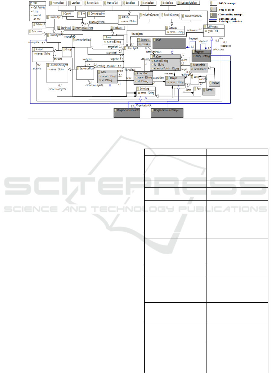
Figure 1: Traceability of BPMN and use case meta-model concepts.
are reflected in the appropriate use case and se-
quence of BPMN elements, promoting transpar-
ent consistency.
3.1.2 Traceability of the Design Sequence
Diagram Meta-Model and the BPMN
Meta-Model
To establish traceability between BPMN and the de-
sign sequence diagrams, the first crucial step involves
defining or identifying appropriate mappings between
BPMN and conceptual sequence diagrams. In exist-
ing literature, (Bouzidi et al., 2020) have developed
a semantic mapping between BPMN and UML ar-
tifacts, accompanied by model transformations from
BPMN to design sequence diagrams structured ac-
cording to the MVC design pattern. These transfor-
mations include mapping BPMN looping activities to
looping combined fragments, representing an empty
lane as an actor, and more. This paper leverages
the semantic mappings established by (Bouzidi et al.,
2020) to establish traceability between BPMN and de-
sign sequence diagrams. This detailed mapping can
be found in Table 2, which provides a clear and con-
cise overview of the relationships between the rele-
vant concepts of BPMN and the design sequence di-
agram structured according to the MVC architectural
pattern.
(Bouzidi et al., 2020) proposed BPMN-to-
sequence diagram transformation rules that operate
on each element of a canonical fragment F. There-
fore, this mapping is devoted to each fragment in
the BPMN model. Moreover, the sequence diagram
meta-model concepts are structured according to the
MVC design pattern because the proposed BPMN-to-
Table 2: Mapping of BPMN and UML sequence diagram
meta-model concepts.
BPMN concept UML concept
Fragment Interaction (frame) ,
Control lifeline , Bound-
ary lifeline , Entity
lifeline
Empty lane/ Empty pool Actor
Data input/ Data output/
Data object/ Data store
Entity lifeline
Automated task(user
task, send task, receive
task, service task, busi-
ness rule task, script
task)
Message
Signal event Message
Error event/ Cancel
event
Control lifeline , Bound-
ary lifeline , Message ,
Combined fragment ,In-
teraction operator Break
Compensate event Control lifeline , Bound-
ary lifeline , Message
Loop task Combined fragment ,In-
teraction operator Itera-
tion (loop)
Exclusive/ Inclusive
gateway
Combined fragment ,In-
teraction operator Alter-
native(Alt)
Parallel gateway Combined fragment , In-
teraction operator Paral-
lel(Par)
Task that appears in
multiple fragments , In-
clusive/ Exclusive gate-
way between two differ-
ent fragments
Interaction use
ENASE 2024 - 19th International Conference on Evaluation of Novel Approaches to Software Engineering
516

sequence diagram transformation rules base on this
pattern. In addition, the majority of the relation-
ships between the overlapping concepts in the BPMN
and UML sequence diagram meta-models are one-to-
many or many-to-many (cf. table 2. This is primarily
caused by the significant degree of heterogeneity be-
tween the BPMN and the sequence diagram artefacts.
In order to simplify our explicit trace meta-model, we
have restricted our mapping to the definition of trace
links in the form of new associations rather than new
traceability meta-classes. The aforementioned trace
meta-classes are used once more to define traceabil-
ity between BPMN and conception sequence diagram
concepts.
Figure 2 shows an excerpt from the meta-model
used to trace the sequence diagram and BPMN meta-
models. It covers the fundamental artifacts of BPMN,
the sequence diagram meta-model, and reused trace-
ability concepts for the sake of readability.
It’s important to mention that all use case concept,
BPMN concepts, traceability links, and existing as-
sociations defined in the integrated trace metamodel
are not presented in this extract of the explicit trace
metamodel remain valid.
In this extract of the explicit trace metamodel,
white meta-classes represent the BPMN concepts, vi-
olet meta-classes represent the MVC design pattern-
compliant conception sequence diagram meta-model
concepts, whereas dark grey meta-classes are used to
represent new concepts. The existing associations are
represented by the black associations, while the new
proposed trace links are represented by the blue asso-
ciations.
Notable aspects of these traceability efforts in-
clude:
• Targeted Trace Links: The mapping establishes
specific trace links between related concepts from
BPMN and sequence diagram meta-models. For
instance, it defines associations connecting Loop
combined fragments with activity meta-classes,
indicating how loops in BPMN correspond to ac-
tivities in sequence diagrams.
• Associations with Multiplicity: The multiplic-
ity of associations reflects the different nature of
the relationships between concepts. For example,
trace links from activation and exclusive gateways
to Alt (connected shards) are set to a multiplicity
of 1.*, meaning that each port in the fragment cor-
responds to at least one linked ”Alt” fragment.
• Composition for End-to-End Integration:
Composition links between Use Case Support
Fragments (UCsF) and sequence diagram ele-
ments demonstrate the end-to-end integration
of these elements. UCsF can contain linked
lifelines, messages and fragments, effectively
representing the fragment components supported
by a use case.
3.2 Instantiating the Integrated
Traceability Metamodel
The second phase of the method focuses on estab-
lishing traceability between BPMN and UML arti-
facts at the model level. It introduces the BPM-
NTraceISM diagram, a derivative of the integrated
tracing metamodel, serving as a unified platform for
designing relationships between BPMN and UML
components. This diagram enables transparent dis-
play and querying of traceability information, en-
hancing analytical efficiency, reducing effort in iden-
tifying changes, and providing a foundation for accu-
rate planning and cost estimation of business model
modifications. The BPMNTraceISM diagram main-
tains original names and notations for clarity, adopt-
ing representations aligned with established BPMN
and UML notations to ensure understanding for both
businesses and software developers. Subsequent sec-
tions delve into graphical notations and representa-
tions for BPMNTraceISM elements.
3.2.1 BPMNTraceISM Artifacts Retain Their
Initial Notations
The semantic mapping we based on to define an in-
tegrated tracking metamodel extend into the domain
of specific BPMN and UML concepts. However, it
should be noted that not all BPMN concepts are di-
rectly compatible with their UML counterparts and
vice versa. For example, the BPMN start event has no
direct equivalent in UML, although there are UML se-
quence diagram elements such as Seq combined frag-
ments and Ignored combined fragments do not cor-
respond to any BPMN concepts. In the context of
the BPMNTraceISM diagram, it becomes possible to
identify UML artifacts that lack direct BPMN equiv-
alents.
In Table 3, we identify key BPMNTraceISM arti-
facts that do not have direct counterparts and explain
their unassigned status.
3.2.2 BPMNTraceISM Traceability Artifacts
Within the framework of the integrated trace meta-
model, we introduce three novel traceability concepts,
namely UCsF, OUActor, and OUPackage. These
concepts serve the purpose of unifying BPMN and
UML elements, requiring unambiguous and univer-
sally comprehensible graphic notations. These nota-
Comprehensive Traceability Framework for Synchronizing Design UML Sequence Diagrams with a BPMN Diagram
517
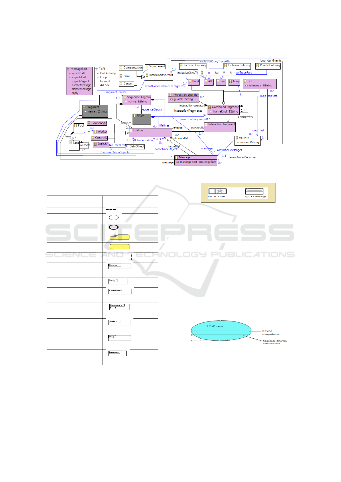
Figure 2: Traceability of the BPMN meta-model and the UML sequence diagram meta-model.
Table 3: Graphic notation of BPMNTraceISM concept
identified from non-overlapped artifacts.
BPMNTraceISM ele-
ment
Graphical notation
Annotation flow
Start event
End event
Manual task
Normal task
Group
Critical combined frag-
ment
Seq combined fragment
Consider combined
fragment
Assert combined frag-
ment
Strict combined frag-
ment
Neg combined frag-
ment
Ignore combined frag-
ment
tions are thoughtfully crafted to be accessible and fa-
miliar to both software and business designers, ensur-
ing a seamless understanding of the BPMNTraceISM
diagram.
The graphic notation of OUActor, which har-
monizes the functionalities of a BPMN lane and a
UML actor, amalgamates elements drawn from the
Figure 3: Graphical notation of OUActor and OUPackage.
graphic notations of both BPMN and UML. Similarly,
OUPackages are represented using a fusion of lane
and UML package graphic notations (cf. Figure 3).
For UCsF, an entity that extends a UML use case
and inherits its attributes, a more intricate symbol is
warranted. The notation for UCsF builds upon the
foundation of the UML use case notation but ex-
tends it by incorporating two distinct compartments.
These compartments are dedicated to encapsulating
BPMN elements and design sequence diagram ele-
ments that are associated with the UCsF (cf. Figure
4). This compartmentalized approach empowers de-
signers with the flexibility to selectively reveal or con-
ceal these elements, thereby effectively managing the
inherent complexity.
Figure 4: UCsF notation.
4 IMPLEMENTATION
To prove the feasibility of proposal in the practice, we
have developed a fully graphical modelling tool bap-
tized BPTraceISM (Business Process model Traced
with Information System Models).
To implement the BPTraceISM tool, we used
ENASE 2024 - 19th International Conference on Evaluation of Novel Approaches to Software Engineering
518
Eclipse EMF to implement the external trace meta-
model and Eclipse GMF to specify the concrete no-
tation for the BPMNTraceISM diagram artifacts. In-
deed, this modelling tool is a fully functional graph-
ical editor. It conforms to our external trace meta-
model and permit to show and manage the trace links
between the BPMN model, and the UML use case and
the UML sequence diagram, concurrently. BPTra-
ceISM can be integrated with other modelling tools
to improve their modelling capabilities. To make our
modelling tool available in any Eclipse environment
without needing to start an Eclipse runtime, we im-
plement it as an Eclipse plugin.
The BPTraceISM construction process consists of
two basic phases; (1) the definition of the modelling
tool and (2) the definition of the plug-in that supports
it. The first phase begins with the implementation of
the external meta-model according to the ecore meta-
modelling language. Next, we develop a toolkit to de-
sign instances of the meta-model classes. In the sec-
ond phase, we are developing functionality that sup-
ports the modelling tool. Subsequently, we build an
update site to ensure the portability of our plug-in and
allow its installation via any Eclipse update manager.
5 CASE STUDY
To illustrate the theoretical feasibility of our traceabil-
ity method, we apply it on the loan assessment busi-
ness process model token from (Dumas et al., 2013).
As our traceability method operates on each ele-
ment of a canonical fragment F. Therefore, we limit
the application of our traceability method on a frag-
ment of the business process loan assessment called
assess loan application of (see Figure 5). It is im-
portant to note that this traceability method is de-
voted to each fragment in the BPMN model. More-
over, the conception sequence diagram meta-model
concepts are structured according to the MVC design
pattern because the proposed BPMN-to-sequence di-
agram transformation rules base on this pattern.
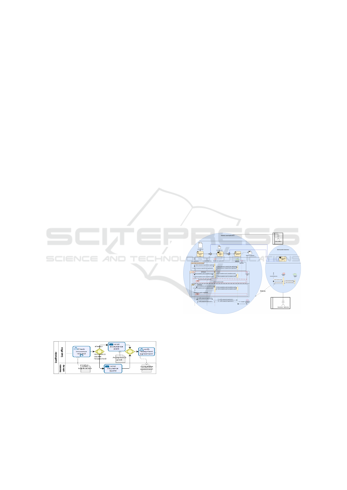
Figure 5: The business process of the fragment loan appli-
cation.
The assess loan application is coupled with insur-
ance provided at discounted prices. When submitting
their insurance request to the loan officer, an appli-
cant expresses its interest in a home insurance plan.
Then, the Laon officer check the insurance request. If
it is accepted, Loan officer send an acceptance pack
to the applicant. The acceptance pack may be joined
with an insurance quote. The sub-process ends with
the verification of the repayment agreement.
In this fragment, we assume that the activity send
insurance quote task appears in other subprocess of
the business model loan assessment.
In this section, we show how we can combine the
different model artifacts (artifacts of source and target
models) within single unified model using our trace-
ability method.
To obtain the corresponding use case model or the
conception sequence diagram of the fragment Asses
loan application some model transformation may be
applied. However, model transformation is enable
to represent explicitly the semantic relationships be-
tween business and IS models. Indeed, use cases
are represented as black boxes and they do not ex-
plain what it supports from business process activ-
ities (or tasks). In addition, the business modeling
and IS modeling teams continue to work separately.
Thus, each modification of the assess loan applica-
tion fragment requires regenerating the corresponding
conception sequence diagram and the use case dia-
gram, which is not a good practice. Using our BPM-
Figure 6: BPMTraceISM diagram of assess loan applica-
tion.
TraceISM diagram makes it possible to model to-
gether within the same diagram the Asses Loan appli-
cation fragment, the corresponding use case diagram
artifacts and the corresponding conception sequence
diagrams. Consequently, it is easy to perceive the
semantic relationships and correspondences between
the use cases, conception sequence diagram and the
BPMN fragment artifacts. Indeed, we can see that the
use case Assess loan application supports the actions
check insurance request, verify repayment agreement
and send acceptance pack. Moreover, each change
fulfilled within the fragment business process leads
automatically to the change of the use case and the
Comprehensive Traceability Framework for Synchronizing Design UML Sequence Diagrams with a BPMN Diagram
519

conception sequence diagrams. For instance, when
a task is added to the UCsF assess loan application,
the corresponding fragment will be automatically up-
dated. Thus, they are kept continuously aligned with
each other. On the other hand, no information of the
BPMN model has been lost. Further, this integrated
specification of different features facilitates the analy-
sis of the links between the different source elements.
So, the impact of changing any of the existing ele-
ments in this diagram is now straightforwardly con-
cluded.
Figure 6 depicts the BPtraceISM diagram speci-
fies together the fragment Asses loan application pre-
sented in Figure 8, the corresponding conception se-
quence diagram presented in Figure 10. as well as the
use cases which represent this fragment.
6 CONCLUSION
The works conducted in this paper fit in the con-
text of model-based development of information sys-
tems and their alignment with business process mod-
els. Indeed, we have defined a traceability method for
BPMN and the UML models that acts at the meta-
model and the model levels. Hence, we firstly defined
an external trace meta-model that incorporates all the
BPMN and the UML elements (use case, design se-
quence diagram,), and traceability links between in-
terrelated elements. Then, we have defined a new di-
agram baptized BPMNTraceISM coforms to the trace
meta-model. This diagram promotes communication
between business and software modelling teams and
allows them working together within a single unified
model. The joint representation of both BPMN and
UML model elements enables to drill down and easily
trace any BPMN element to its corres ponding soft-
ware elements.
To prove the feasibility of our traceability method
in the practice, we developed a modelling tool for
designing and handling BPMNTraceISM diagrams in
accordance with the proposed integrated trace meta-
model. Further, we applied the proposed approaches
to a typical case study.
In future research, we are looking forward to op-
timise our editor to support traceability and synchro-
nization between BPMN models and other UML dia-
grams.
REFERENCES
Bouzidi, A., Haddar, N., Abdallah, M. B., and Haddar, K.
(2017). Deriving use case models from bpmn models.
In 2017 IEEE/ACS 14th International Conference on
Computer Systems and Applications (AICCSA), pages
238–243. IEEE.
Bouzidi, A., Haddar, N. Z., Ben-Abdallah, M., and Haddar,
K. (2020). From bpmn to sequence diagrams: Trans-
formation and traceability. In ENASE, pages 438–445.
Bpmn, O. (2008). Business process model and notation.
http://www.bpmn.org (Accessed 17.04. 2017).
Dumas, M., La Rosa, M., Mendling, J., and A Reijers, H.
(2013). Fundamentals of business process manage-
ment. Springer.
Ghiffari, K. A., Fariqi, H., Rahmatullah, M. D., Zul-
fikarsyah, M. R., Evendi, M., Fathoni, T. A., Giarfina,
N., Zaman, B., and Raharjana, I. K. (2023). Bpmn2
user story: Web application for generate user story
from bpmn. In AIP Conference Proceedings, volume
2554. AIP Publishing.
Haidrar, S., Anwar, A., and Roudies, O. (2017). On the use
of model transformation for requirements trace mod-
els generation. In 2017 International Conference on
Wireless Technologies, Embedded and Intelligent Sys-
tems (WITS), pages 1–6. IEEE.
Kharmoum, N., Retal, S., El Bouchti, K., Rhalem, W., and
Ziti, S. (2023). An automatic alignment of the busi-
ness process and business value models: a novel mda
method. Indonesian Journal of Electrical Engineering
and Computer Science, 30(1):501–509.
Khlif, W., Daoudi, S., and Bouassida, N. (2022). From
bpmn model to design sequence diagrams. In ICEIS
(2), pages 577–588.
Kleppe, A. G., Warmer, J. B., and Bast, W. (2003). MDA ex-
plained: the model driven architecture: practice and
promise. Addison-Wesley Professional.
Licardo, J. T. (2023). A Method for Extracting BPMN
Models from Textual Descriptions Using Natural Lan-
guage Processing. PhD thesis, University of Pula.
Faculty of Informatics in Pula.
Meier, J. and Winter, A. (2018). Traceability enabled
by metamodel integration. Softwaretechnik-Trends,
38(1):21–26.
Moreira, J. R. P. and Maciel, R. S. P. (2017). Towards a
models traceability and synchronization approach of
an enterprise architecture. In SEKE, pages 24–29.
Qiao, Y., Liu, Z., Wang, J., and Li, B. (2023). Crossover
service requirements: Analysis and design. In Conver-
gence in Crossover Service, pages 67–108. Springer.
Specification, O. A. (2017). Omg unified modeling lan-
guage (omg uml), superstructure, v2. Object Manage-
ment Group, 70.
ENASE 2024 - 19th International Conference on Evaluation of Novel Approaches to Software Engineering
520
