
A Rule-Based Log Analysis Approach for State-Machine Governed
Systems
Jeroen Zwysen
2 a
, Felicien Ihirwe
1 b
, Ken Vanherpen
1 c
, Maarten Vergouwe
1 d
,
Umut Caliskan
2 e
and Davy Maes
1 f
1
CodesignS, Flanders Make vzw, Oude Diestersebaan 133, Lommel, Belgium
2
MotionS, Flanders Make vzw, Oude Diestersebaan 133, Lommel, Belgium
fl
Keywords:
Log, Logging, Log Analysis, Log Comprehension, Log Compression, Log Parsing.
Abstract:
Logs are used in programming for various purposes, ranging from failure analysis to software comprehension.
However, the processing of logs is hindered by the lack of structure in the logs, the required domain knowledge
for interpretation, and a lack of tooling. In this paper, a novel approach that includes structured log generation
and rule-based log analysis is presented. Targeting state machine-governed systems, the approach relies on
developers’ knowledge during design time to allow hierarchical grouping of logs and standard visualization
of the logs during the analysis. This allows automated failure diagnosis and localization without full system-
wide domain knowledge as well as providing a historical context of the system during a failure event. To
better evaluate the effectiveness of the approach, two use cases, namely a Virtual Coffee Machine (VCM) and
an Automated Mobile Robot (AMR) are showcased and analyzed.
1 INTRODUCTION
As the complexity of systems evolves, so does the
hustle and effort needed to identify the cause of a fail-
ure. When a run-time failure occurs, the developers
mostly turn to the log files to try to debug and under-
stand where such issues come from. The developer
knows or has an idea of where to look; however, go-
ing through the logs manually can be cumbersome.
Log data in the form of execution logs, is used
for various purposes, such as issue analysis, system
verification and improvement, test development, and
company decision-making (He et al., 2021; Yang
et al., 2023). However, the semi-structured or fully
unstructured nature of the log entries leads to many
challenges during software development and log anal-
ysis. These include the challenge of parsing and inter-
preting log entries, the challenge of locating faults in
full system logs where combined domain knowledge
is required, as well as frequent software updates that
a
https://orcid.org/0000-0002-7370-416X
b
https://orcid.org/0000-0002-4463-6268
c
https://orcid.org/0000-0002-1684-0173
d
https://orcid.org/0000-0001-9791-2679
e
https://orcid.org/0000-0002-4431-4656
f
https://orcid.org/0000-0001-7744-7730
include logging statement changes (He et al., 2021;
Yang et al., 2023).
When it comes to controlled systems, the state ma-
chine is one of the major system’s functional imple-
mentations for describing how the system operates.
Normally, a state-machine-governed system relies on
a finite set of states, transitions between these states,
and a set of rules, conditions, or simply events to tran-
sition from one state to another (Wilson, 2016). As
the system becomes more complex, ensuring the ac-
curacy and consistency of the logs across distributed
components of the system is still an issue (He et al.,
2021).
Multiple studies and software tools try to answer
the questions of what, where, and how to log to tackle
these challenges (He et al., 2021). LogEnhancer
(Yuan et al., 2011) and the tools developed in (He
et al., 2018; Li et al., 2018; Liu et al., 2021) automati-
cally add and suggest relevant log data and properties
for existing log statements, while LogAdvisor (Zhu
et al., 2015), Errlog (Yuan et al., 2012) and Log20
(Zhao et al., 2017) analyze existing source code pat-
terns and code execution to find the optimal locations
for new logging statements. In addition to that, the
approaches in (Cinque et al., 2013) and part of Errlog
(Yuan et al., 2012), analyze source code and identify
coding patterns to which log statements can be added
Zwysen, J., Ihirwe, F., Vanherpen, K., Vergouwe, M., Caliskan, U. and Maes, D.
A Rule-Based Log Analysis Approach for State-Machine Governed Systems.
DOI: 10.5220/0012702300003690
Paper published under CC license (CC BY-NC-ND 4.0)
In Proceedings of the 26th International Conference on Enterprise Information Systems (ICEIS 2024) - Volume 2, pages 77-88
ISBN: 978-989-758-692-7; ISSN: 2184-4992
Proceedings Copyright © 2024 by SCITEPRESS – Science and Technology Publications, Lda.
77

(e.g., exception handling or function call patterns).
Regarding the state-machine-governed log analy-
sis, the approaches such as log differencing by (Tsoni,
2019), testing Real-Time Operating System (RTOS)
(Shi et al., 2011), rule-based penetration detection (Il-
gun et al., 1995), service behavioral analysis (Gold-
stein et al., 2017), and SALSA (Tan et al., 2008) lever-
ages state machine models for describing the system
behavior from logs and then further it with log anal-
ysis. Although this is the case, there was no support
for log formalization whatsoever.
According to (Yang et al., 2023), It is not clear
why these tools are not yet fully utilized in common
practice. While the exact reason is not yet clear, it is
reported in the literature that the success of automated
tools can be highly dependent on the structure of the
logs being analyzed. In addition to that, these tools
still require some extra tooling or pre-processing for
them to reach a high degree of accuracy (Zhu et al.,
2015; Hamooni et al., 2016; Sedki et al., 2023; Zhang
et al., 2023).
In this paper, a structured log generation approach
and a rule-based multi-level log analysis approach are
presented and tested. The approach directly addresses
one of the biggest challenges in the log generation
and analysis domain: log-based system fault localiza-
tion in a complex application with multi-disciplinary
expertise involved. This challenge is significant for
systems consisting of software and hardware (e.g.,
embedded control of physical systems) (Yang et al.,
2023), where the expertise of the different developers
can be very different.
The novel approach relies on a structured logging
schema and automated log statement injection mech-
anisms. The system generates systematically struc-
tured logs that can be analyzed on the fly. In addi-
tion to that, the LogAn analysis tool is presented. The
tool relies on predefined rules to automatically parse
log entries into events, perform complex event pro-
cessing to distinguish expected from unexpected state
machine behavior on component and system level,
provide automated dynamic visualizations, create on-
the-fly queries, and filter the events to achieve high-
desirable outputs.
The result of the log analysis provides a hierarchi-
cal view of the log events, abstracting code execution
away on the higher levels and requiring less detailed
system knowledge when analyzing the log data in a
top-down approach. The presented approach allows a
high degree of automation from the design phase up
to the maintenance phase of state machine-governed
systems. To assess the effectiveness of the proposed
approach, two validation cases namely a Virtual Cof-
fee Machine (VCM) and an Automated Mobile Robot
(AMR) were used and the results are presented.
Consequently, we summarize the contribution of
this paper as follows:
1. A unified logging schema is presented to guide the
logging mechanism for state machine-governed
systems.
2. We present a rule-based logging approach and a
supporting tool able to perform log statement in-
jection.
3. We present LogAn, an automated log analysis tool
targeting state-machine-governed systems.
4. We present the results from two different exper-
imental cases VCM and AMR to showcase effi-
ciency of the approach as well as the capability of
the supporting tool.
The remainder of the paper is structured as fol-
lows: Section 2 presents the proposed approach, cov-
ering the logging schema, log statement generation,
and injection, as well as log analysis. Section 3
presents the experimental results from the two use
cases, VCM 3.1 and AMR 3.2. Section 4 presents the
related work, while Section 5 discusses the advantage
as well as the points of improvements to be addressed
in the future. Finally, Section 6 concludes the paper.
2 PROPOSED APPROACH
Our proposed approach philosophy is threefold and
comprises the following main parts:
• Unified Logging Schema: Logging guidelines
that enforce structured recording of relevant input,
initial states, final states, and output values of the
system’s state machine (Section 2.1).
• Log Statement Generation and Injection: Fol-
lowing the schema, log statements are inserted
into the source code in an automated fashion, re-
lying upon logging libraries to record the systems
logs (Section 2.2).
• Automated Rule-Based Log Analysis: The gen-
erated logs are analyzed in an automated fash-
ion thanks to an advanced rule-based log analysis
tool (LogAn). In which it is possible to perform
on-the-fly filtering, visualization, and debugging
(Section 2.3).
2.1 Unified Logging Schema
The overall behavior of the controlled system can be
described in different ways, namely state machine-
based behavior and client-server-based behaviour.
ICEIS 2024 - 26th International Conference on Enterprise Information Systems
78

These descriptions are not mutually exclusive and
put a different focus on relevant data and opera-
tional goals. In this paper, we are interested in state-
machine-governed systems.
2.1.1 State Machine Theory
A state machine is governed by a set of states, tran-
sitions between these states, and a set of rules, con-
ditions, or simply events to dictates hows a transition
from one state to another occurs (Lee and Yannakakis,
1996). The state machine can be mathematically rep-
resented as follows:
SY S =< T, X, Ω, Q, δ,Y, λ > (1)
In the above equation, the state set Q is defined as
a list containing tuples of state variables (e.g., the wa-
ter temperature and water level). Likewise, we define
the input set X as a list of all possible system inputs
(e.g., a sensor reading or a user input signal). At a cer-
tain time T, a certain input or sequence of inputs will
trigger the state machine. This is called an input seg-
ment Ω. Given the input set and the state, the system
will transition to a new state, formalized by means of
the transition function δ. Concerning the outputs of
the system, we define the output set Y and the output
function λ. The output set Y is a list of all possible
system outputs (e.g., the actuation of a heating ele-
ment). The output function λ defines which output
(of the output set) will be set when the system is in a
certain state Q.
2.1.2 State Machine Logging
Given the theory provided (see Section 2.1.1), the fo-
cus in this schema lies on logging relevant inputs,
states, transitions, and outputs, which are essential to
identifying the current state of the state machine’s be-
havior. Table 1 presents the logging schema of the
state-machine behavior.
Table 1: Proposed logging schema of the state-machine be-
havior.
Statement Explanation
Input ω in Ω The state machine input (SMIN)
State q in Q The current state (SMCS)
Transition q
n
ew = δ(ω, q) The triggered (new) state (SMNS)
Output y in Y The state output (optional) (SMOU)
The Output in Table 1 are indicated as optional
for multiple reasons as they are coupled to the states
of the state machine by the output function λ. An ex-
ample of an implementation of the logging schema is
shown in Listing 1. In this example, it is assumed that
the default variables from Table 2 are already known
and logged by the “log” service.
Listing 1: Logging schema implementation example.
int state1;
int stateMachine(int inp1, float inp2, float* outp1) {
log(SMIN, inp1, inp2);
log(SMIS, state1);
... // includes state machine code, adapting state1
int ret = 32; // assign return value
...
log(SMNS, state1);
log(SMOU, ret, *outp1);
return ret;
};
2.1.3 Controller Software Logging
When logging the state of machine execution, it is
critical to know "what to log" and "why" it is im-
portant to do so. In our logging mechanism, we pro-
pose a combined logging of both controlled software
as well as the actual state machine data. In Table 2,
the proposed logging variables for controller software
are presented:
Table 2: Proposed logging variables for controller software.
What Explanation
Timestamp Timestamp the logging statement was executed
Severity Severity of the logging message (DEBUG, INFO,
WARNING, ERROR, etc.)
Component ID An identifier grouping relevant functions (file or a
class name).
Function ID Name of the function in which the logging state-
ment resides
Object ID (Optional) identifier of the object (instance of a
class)
Thread ID (Optional) ID of the thread from which the logging
statements were executed
2.2 Log Statement Generation and
Injection
The log statement generation and injection approach
involves adding logging statements at the start and
end of a function. The injected log statements follow
the schema discussed in Section 2.1 which includes
relevant inputs, initial states, final states, and output
values. This information is fundamental to the in-
terpretation of state-machine behavior. As explained
later in Section 2.3, this set-up ultimately enables au-
tomated hierarchical grouping of the log data/function
calls and classification into known and unknown sys-
tem behavior.
2.2.1 Log Entries Definition
The log statement generation approach starts with the
formal definition of all of the possible log entries. In
A Rule-Based Log Analysis Approach for State-Machine Governed Systems
79

our case, each log entry is made of the system con-
troller and state machine behavioral data. In doing so,
the basic format is shown below:
timestamp [severity] {source}{threadID} SMData
In the expression above, the {source} part is de-
fined as the combination of the component ID and
function ID (Refer to Table 2). The expression is de-
fined as in the expression below:
componentID.functionID
To satisfy the logging of SMData, four different
log entries should be defined to reflect the four main
variables as defined in the schema 2.1. They in-
clude log entries to report the inputs, initial state, end
state, and output values of the relevant functions. The
recording of SMData entry is made as a "key:value"
fashion with the log message as key and the event type
as the value (See in Table 3). The definitions are then
stored in a header file for further automated process-
ing.
Table 3: SMData entry format.
Log message Event type
"inputs received: %s" FuncInputsRec
"initial state: %s" FuncInitState
"end state: %s" FuncEndState
"returns: %s" FuncReturn
2.2.2 Log Statement Generation and Injection
The log statement generation is done thanks to a cus-
tom text-to-text transformation that translates the log
entries into injectable source code. Currently, C++
source code types are supported. The transformation
takes the custom log entry files and translates each log
entry line into the corresponding log statement code.
In doing so, it takes into account the boilerplate code
related to log statement formatting, adding the times-
tamp, logging level, and so on (e.g., class and func-
tion/member name) to the log entries from Table 3.
When the log statement generation is done, the
generated source file is then passed to a custom
ANTLR/Python to automatically insert the log state-
ments into the source code. The functions that need to
be provisioned with log statements are those that han-
dle the state transitions and the outputs of the state
machine. It depends on the exact implementation of
the state machine—if this is one single function or if
the functionality is split over multiple functions.
An example of the log statements that are added to
the source code is provided in Listing 2. The function
passes on the message ID, e.g., "INPREC" for the "in-
puts received" message, and the relevant data, inputs,
states, or outputs, while the logger class in the ex-
ample adds the additional information of timestamp,
source, and thread ID to complete the log entry in the
format shown in Table 3.
Fully automating the injection of log statements
can be difficult and highly dependent on the structure
of the state machine code itself. It is recommended
to use state-machine automated code generators, for
instance, Simulink StateFlow
1
to generate the state-
machine code. The tool is aware of which inputs,
states, and outputs are key to the state machine and
has pre-defined templates for implementing them.
Listing 2: An example of the generated log statements.
# State machine function
def __SM(self):
logger.LOG_MSG(self.__logger, "INPREC", "i1_start="
+str(self.i1_start)+"; i2_num="+str(self.i2_num))
logger.LOG_MSG(self.__logger, "STATEINIT", "SM_state=
"+str(self.__SM_state))
... # state machine code (updating self.__SM_state)
logger.LOG_MSG(self.__logger, "STATEEND", "SM_state=
"+str(self.__SM_state))
logger.LOG_MSG(self.__logger, "RETURN", "o1_num=
"+str(self.o1_num))
2.3 Log Analysis
The general workflow for log analysis consists of
parsing the log entries into low-level code execution
events and condensing this information in a hierar-
chical, multi-step approach towards high-level events
that can be interpreted at a system-wide level, requir-
ing limited implementation or domain knowledge.
Every step requires limited expertise to implement,
comparable to the expertise that is already required
for implementation.
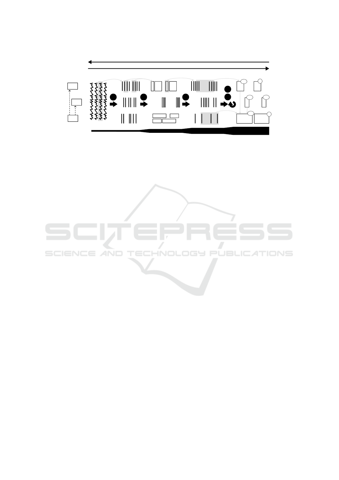
Figure 1 depicts the high-level view of the auto-
mated analysis which is divided into five main steps
namely (1) log entry events from text, (2) function
calls from log events, (3) state changes from function
calls, (4) state machine cycles from state changes, and
(5) identification of known or unknown cycles.
In the first step, the log entries, generated by the
log statements described in section 2.3, are parsed to
extract all of their properties, including their source,
e.g., component and function ID, and state machine-
specific properties: inputs, states, and outputs. The
parsing rules are fixed and only depend on the exact
logging scheme chosen in the implementation of the
log statements, such as the one given in Table 3.
In step two, the events attributed to one function
execution, combining the log entries from the start
1
https://www.mathworks.com/products/stateflow.html
ICEIS 2024 - 26th International Conference on Enterprise Information Systems
80
C3
C2
Log text files
Log entries
Log analysis processing
System behavior analysis
Function calls
State transitions State machine cycles
Timescale
C1
1 2 3
4
5
✔4
✔6
✔6
✔9
✗
✗
System
Components
Figure 1: Log analysis workflow for a system with 3 components C1, C2 and C3, whereby C3 depends on or uses C1 and C2.
and end of the function execution, are grouped into
function call events. This is done by matching the
source of the entry as well as the thread ID. The prop-
erties of these newly generated events contain func-
tion inputs, initial states, end states, and outputs.
In step three, the function call events are then
parsed to extract state transition events. The rules
for identifying a state transition depend on the spe-
cific implementation of the state machine. If external
software is used to automatically generate the code
from design file specifications, the same tool can be
inferred to deduce rules for identifying state transi-
tions from function executions.
In the next step, step four, state machine cycle
events are identified. A state machine cycle is a list of
state transitions that starts at one of the starting states
and ends at one of the ending states. These starting
and end states need to be provided by the state ma-
chine designer. Typical examples of such states are
the idle, error, or reset states. These state machine cy-
cles are identified from the state machine transitions
from analysis step 3, but they are also linked to the
state machine cycles of the components on which the
state machine depends.
So in the example shown in Figure 1, the state ma-
chine cycles of component C3 are also linked to the
state machine cycles of components C1 and C2. This
linkage means that the log processing in step 4 is re-
peated hierarchically, following the same dependen-
cies as the actual code does. Both the starting and
end states, as well as these interdependencies, are re-
quired information that is likely available from project
design files.
In the same step, it is possible to link additional
logged data to a state machine cycle event. An ex-
ample of this could be the maximum temperature of
a hardware component of the system during a certain
state or the state transition. This can be done to add
vital system-dependent context, as assessed by a do-
main expert.
In the final step, step 5, known state machine
cycles are identified. These are cycles that are ex-
pected based on system behavior, but they could also
be cycles that were not known at design time but
identified later on from early testing or bug reports
from clients. Identification of a known cycle can be
done by inspecting the trajectory of states and state
transition times within a state machine cycle event.
However, the additional system-dependent informa-
tion from step 4 can also be used to this end.
For each known cycle, a clear description must
be provided that is understandable using only system
knowledge and not implementation knowledge. Sim-
ilar to step 4, in a system with multiple linked compo-
nents, these known cycles can also be defined for ev-
ery component. During the log analysis phase, these
can then again be hierarchically combined.
The state machine cycles, which are not identified
as known cycles, are thus automatically classified as
unknown cycles and require attention by the devel-
opment team. Either they indicate a fault or the cycle
was not yet correctly identified as a valid cycle. When
the reason for this behavior has been found, it can ei-
ther be fixed or it can be added as a new known cycle
for future log processing. The known and unknown
cycles are shown in Figure 1 with check marks, to-
gether with an ID number linked to its description,
and cross marks.
The different levels of information contained in
the created events are listed in Table 4.
2.3.1 LogAn Tool
For the log analysis, the LogAn tool is proposed
which implements the automated logic explained
above. LogAn automatically converts log entries
from text files to events. Secondly, it provides a visu-
alization of the events as a function of time. Thirdly, it
provides a graphical user interface (GUI) for creating
more complex search patterns. Lastly, it provides a
A Rule-Based Log Analysis Approach for State-Machine Governed Systems
81
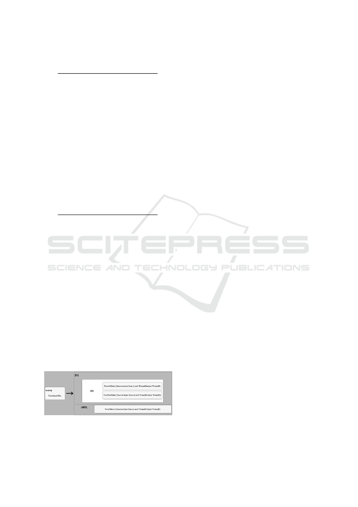
Table 4: Information stored in the different events from Fig-
ure 1.
Log entries
- timestamp
- source, thread ID
- inputs OR outputs OR state
Function calls
- start and end time
- source, thread ID
- inputs, outputs, initial state, and end state
State transitions
- timestamp
- state machine ID
- inputs, outputs, initial state and end state
State machine cycles
- transition times
- state machine ID
- list of states
- references to state machine cycles of sub-components
- (optional) domain-specific data from other log entries
Known cycles
- start and end time
- state machine ID
- known cycle ID and description
- references to known cycles of sub-components
convenient debug environment for the more complex
queries, patterns, and filters.
Inputs for the log analysis tools on the lowest level
are regular expressions that match the structured log
entries defined in Table 3 and extract all properties.
Using this, LogAn generates the log entry events from
the log files. To better represent the events properly,
LogAn uses the EsperTech tool (Inc., 2006) for per-
forming event indexing and querying tasks.
Taking reference from Table 3, the system’s func-
tion calls are automatically extracted based on log
entries with FuncInputsRec and FuncReturn event
types. This generates new grouped events for fur-
ther processing. The log entries FuncInitState and
FuncEndState can be optionally presented in between
these to report state variables and changes to them.
The query that can be used to detect this chain of
events is programmed using the GUI provided by Lo-
gAn, as shown in Figure 2. Note: in the query, the
log entry’s source and thread ID are checked to make
sure they originated from the same function call.
Figure 2: An example of LogAn interface for creating the
query.
Listing 3: Textual representation of the query in Figure 2.
select * from
pattern[(every (Input=FuncInputsRec) ->
((InitState=FuncInitState(Source=Input.Source
and ThreadID=Input.ThreadID) OR EndState =
FuncEndState(...))) until Return=FuncReturn(...)
)]
The visual helps in grouping the statements logi-
cally together and showing their causal connections.
The state transition is dependent on the exact imple-
mentation of the state machine. Taking an example
of a system in which the state transitions are handled
by a single function that changes the state of one vari-
able. A very simple query to detect state transitions
can be written as in Listing 4
Listing 4: State transition query example.
select * from
pattern[(every(EFuncCall(InitStateValues!=
EndStateValues)))]
Where:
EFuncCall: Events generated in step 2
InitStateValues: Initial state values
EndStateValues: End state values
In the above equation, when a match is found, a
new state transition event is generated, which needs to
be linked with a specific state machine. This mapping
of matches on function calls to state machines also
needs to be provided by the developer.
The state machine cycles consist of transitions
from starting to ending states. To achieve this, a pat-
tern must be specified to look for all state transitions
for the given state machine ID that has an initial state
that matches one of the provided starting states, after
which it will look for all other state transitions un-
til one contains an end state as the final state. When
this query matches, it will generate a new state ma-
chine cycle event with a list of transitions, together
with their timings, as properties.
In addition to state transition events, the queries
allow for the collection of other events that occurred
before or during the state machine cycle events. This
allows for the collection of other, potentially more un-
structured, data that provides additional information
on the system. The first use of this ability is to collect
state machine cycles of sub-components.
An example of this would be C3 from Figure 1:
the C3 state machine cycles also collect the state ma-
chine cycle events of C1 and C2. The identifica-
tion of the known state machine cycles, and thus also
the unknown ones, is very application-dependent, but
mainly, it consists of matching the state machine tra-
jectory to trajectories, matching specific system be-
havior. This can be defined in LogAn by matching
every state machine cycle event and checking the list
of states for the correct one.
ICEIS 2024 - 26th International Conference on Enterprise Information Systems
82
3 EXPERIMENTAL RESULTS
The new method can be applied to systems, including
software, largely governed by state machine behavior.
While many, if not all, systems can be described us-
ing state machines, the method from this paper is most
effective for state machines with many possible paths
to traverse, whereby the transitions are heavily influ-
enced by inputs. To better evaluate the effectiveness
of the approach as well as the supporting tool, two
different experimental cases, namely "Virtual Coffee
Machine (VCM)" (Sec 3.1) and "Autonomous Mobile
Robot (AMR)" (Sec 3.2) are showcased and analyzed.
3.1 CASE 1: Virtual Coffee Machine
3.1.1 Setup
A Virtual Coffee Machine (VCM) was implemented
to validate the approach based on our knowledge of
how a hardware plant is controlled by a software con-
troller would operate. The controller logic consists
of multiple nested state machines. This results in
the system software consisting of five main compo-
nents: one is the overall system controller, one sub-
component is responsible for checking for sufficient
supplies of beans, water, cups, and trash space, while
the three other sub-components control the cup han-
dler, the bean grinder, and the combined water heating
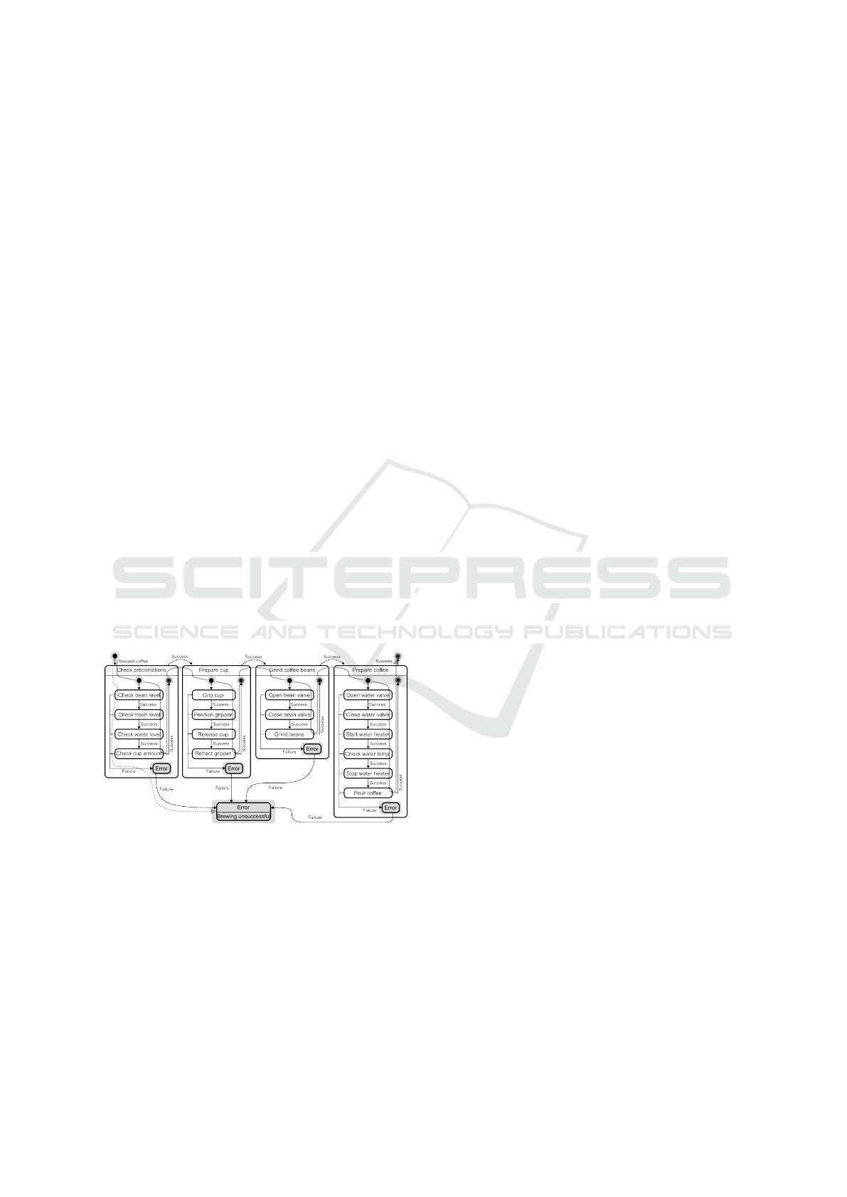
and pouring. The state machine logic is visualized in
Figure 3. In addition, the start and end states are high-
Figure 3: Coffee machine state machine structure with high-
lighting of the start and end states and display of two known
or expected state machine trajectories.
lighted, and the trajectories of two known cycles are
indicated by grey arrows.
For the test setup, only two known cycles are in-
cluded: one cycle occurring when a coffee is success-
fully made and one cycle occurring when the coffee
machine runs out of beans. These cycles are indicated
by the trajectory arrows in Figure 3.
In addition to the virtual coffee machine, a virtual
operator/user is created. This operator tries to get 20
coffees. When the operator is not able to get coffee,
she/he will check the beans, water, cups, and trash to
make sure everything is okay before trying one more
time. This amount of coffee makes sure that all of
the coffee machine supplies will run out at least two
times.
To test the efficacy of the approach for issue local-
ization, 2 artificial bugs are studied:
• BUG 1: The bean sensor logic returns a random
value. The user will sometimes have to try multi-
ple times to get a coffee.
• BUG 2: The sub-component, responsible for
checking for sufficient supplies, skips all of its
steps to check them and instead always returns
successfully. To the user, the coffee machine op-
erates normally when all supplies are full.
3.1.2 Results
In this section, each of the bugs mentioned in section
3.1.1 will be discussed individually.
For the normal run, the log file contains 6000 log
entries, which, in the log analysis steps 2-4, are trans-
lated respectively into 1500 function call events, 350
state transition events, 24 state machine cycles for the
system state machine, and 24 state machine cycles for
the sub-component state machine. The final step 5 of
the log analysis results in the identification of 20 cy-
cles of normal behavior (for both components) and 2
cycles for both components, indicating that the coffee
machine has run out of beans.
These numbers already illustrate the information
compression using this hierarchical way of working.
The system analyzer can now immediately identify
that the coffee machine has operated 20 times suc-
cessfully and failed to deliver coffee two times due to
the machine running out of beans. Two other cycles
are unknown and should be investigated.
The unknown state machine cycles occur not only
at the system but also at the sub-component level. The
state machine cycle event of the sub-component re-
veals that the sub-component goes into an error state
when checking for water and trash space availabil-
ity. Additionally, from a system perspective, these
unknown cycles happen after 10 and 12 successful
coffees.
BUG 1: Random Behavior of the Bean Sensor:
In this case, the intermittent or random behavior of
the bean sensor leads to a suspiciously high amount
of known cycles, indicating that the coffee machine
ran out of beans while still also revealing successful
coffee-making cycles. A screenshot of the informa-
tion displayed in LogAn is shown in Figure 4. In this
screenshot, the second column from the left displays
A Rule-Based Log Analysis Approach for State-Machine Governed Systems
83
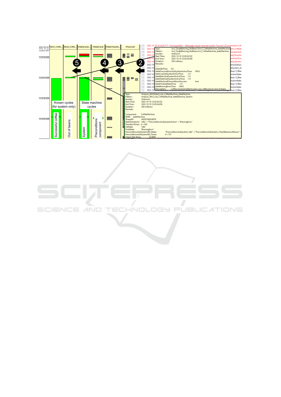
Figure 4: LogAn visualization with an indication of the log analysis steps 2–5 from Figure 1.
the known cycles, indicating that the coffee machine
is failing to brew coffee due to a lack of beans.
It can be seen how this happens twice in a row,
which is not normal (usually the beans are refilled
after a failure). This high-level information should
be revealed to the system expert to consult the sub-
component, the state machine cycle of which reports
a high number of out-of-beans cases. This is again a
difficult case for traditional log analysis methods be-
cause of the intermittent nature of the problem (Jay-
athilake, 2012). The method described in this work
provides an immediate overview of what has hap-
pened visually to the system over a large period of
time.
BUG 2: State Machine is Largely Skipped but
Returns Successfully
The analysis results of the scenario where one of
the sub-component state machines is largely skipped
and always returns successfully indicated that no
known state machine cycles were detected at the sys-
tem level as well as for that specific sub-component
level. Therefore, the fault can be easily located visu-
ally inside the sub-component, where the illegal and
missing state transitions reside. This can be quickly
identified visually in LogAn by the sub-component
domain expert.
This is an interesting outcome, as the coffee ma-
chine itself is operating normally from a user’s point
of view. So the fault is found without an actual report
of failure. As a result, it is particularly difficult to rec-
ognize errors using typical log analysis approaches,
because detecting missing log entries is far more dif-
ficult than identifying erroneous log entries (Tsoni,
2019).
3.2 CASE 2: Autonomous Mobile Robot
3.2.1 Setup
The task of the robot is to create a quality service map
for the private 5G network by launching network tests
in different locations. Different from the Virtual Cof-
fee Machine case, this case was meant to validate our
approach by external developers. In doing so, the de-
veloper was given the logging schema, the log injec-
tion infrastructure and the LogAn tool to go ahead
with log generation and analysis. In the end, with
the help of our approach, the developer was able to
identify different bugs (also discussed below) which
helped in changing/fixing buggy code.
The setup consists of a MIR250 (Robots, 2023),
together with a computer communicating with the
network and running the task planner. To complete
its task, the first software component analyzes a map
of the area and generates optimal waypoints, taking
into account the robot size and network coverage tar-
gets. An example of generated waypoints, which the
robot will try to follow, is shown in Figure 5. When
the list of waypoints is generated, the mission man-
ager instructs the lower software components to fol-
low each of the waypoints in order. Whenever a way-
point is reached, a network coverage test is started. If
the waypoint is not reached, the waypoint is skipped.
This state machine behavior is shown in Figure 6.
Communication between all components, includ-
ing the mission manager, is done using the publish-
subscribe communication protocol. The robot’s ac-
tion state machine, describing the behavior of the
robot as seen by the mission manager, is shown in
Figure 7. We can observe that a larger state machine
ICEIS 2024 - 26th International Conference on Enterprise Information Systems
84
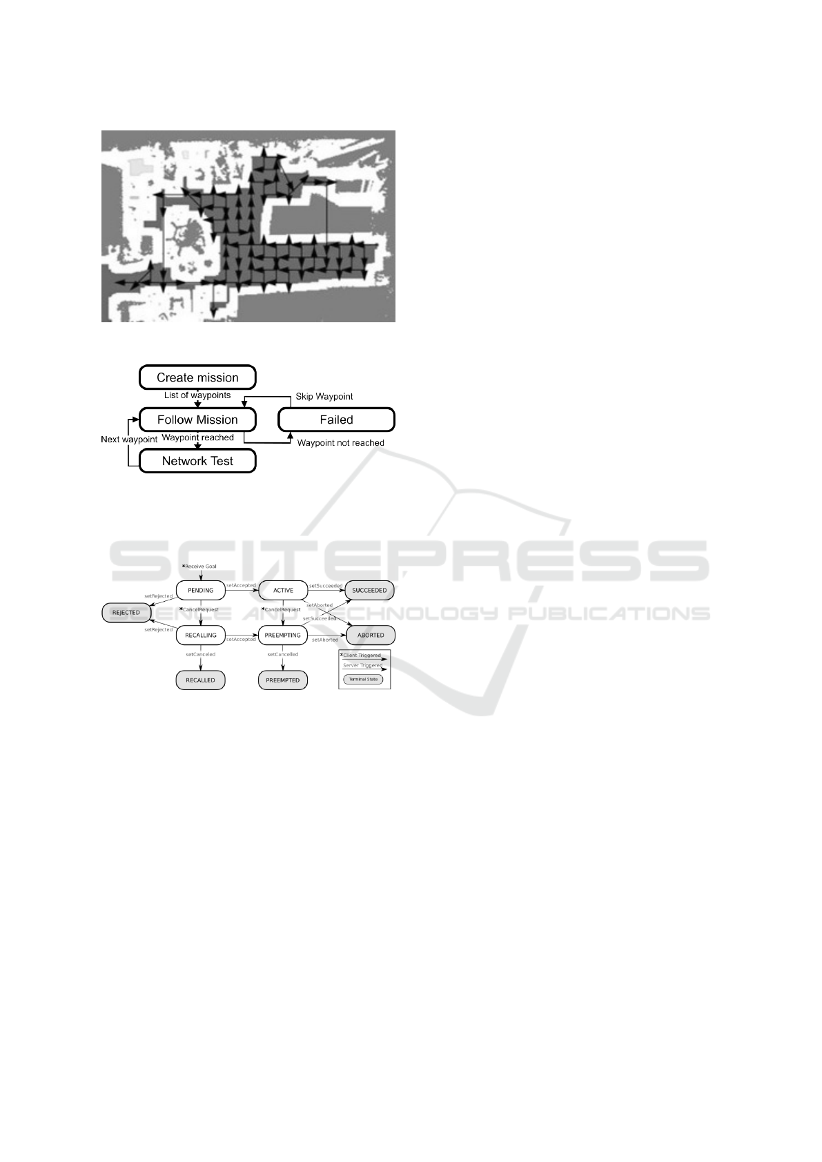
Figure 5: Waypoint generated for complete network test
coverage.
Figure 6: A small state machine of the mission manager
consisting of only 4 states.
of the component interacts with the mission manager
with indicated terminal states (start or end states).
Figure 7: Action server state transitions.
As the main development is done on the mis-
sion manager side, the developer decided to test the
method from this paper on the mission manager code.
No deliberate bugs are inserted in the code, but two
bugs are found thanks to the method in this paper.
In the AMR case, only one known cycle for the
task planner is programmed. This cycle is the AC-
TIVE -> SUCCEEDED -> ACTIVE cycle from Fig-
ure 7 (the PENDING state is skipped).
3.2.2 Results
The first bug that was found was an initialization bug,
where the first state transition was not part of a known
cycle and would go from SUCCEEDED to ACTIVE.
This revealed that the task planner starts up in the
SUCCEEDED state, which was not accounted for in
the code.
A second bug was found in the detection of miss-
ing state transitions. State transition events were
present that were not part of the known cycles and had
end states not matching the next state transition initial
state. This revealed that the code had race condition
issues related to the different execution rates of the
mission manager, running at 2 Hz, and the task plan-
ner, running at 10 Hz. These race conditions affected
the logging code, which was implemented in the mis-
sion manager source code, but could also potentially
impact the general operation of the system.
The general feedback from the developer on the
method was that the analysis and visualization in Lo-
gAn provided good, high-level context on what was
happening and what had happened to the system. This
is perceived as very valuable in conjunction with tra-
ditional log analysis methods for file inspection.
4 RELATED WORK
4.1 Machine Learning-Based Log
Statement Generation
Zhu et al.(Zhu et al., 2015) presented a "learning to
log" approach that offers recommendations on log-
ging during development. They introduced LogAdvi-
sor, a tool that uses machine learning and noise con-
trol to achieve high accuracy in capturing suggestions.
This framework aims to reduce the effort required
to make logging decisions by automatically learning
typical logging practices from existing logging in-
stances while applying them to provide actionable ad-
vice to developers. On the other hand, Liu et al.(Liu
et al., 2021) proposed a learning-based approach to
support developers in determining which variables to
log during software development. They used a neu-
ral network to learn logging "rules" for variables and
recommended which variables should be logged in a
new code snippet.
Furthermore, Zhao et al.(Zhao et al., 2017) intro-
duced Log20, which automates the placement of log
printing statements in software systems without re-
quiring domain knowledge. It uses information the-
ory to determine the near-optimal structure of log
printing statements within a given performance over-
head threshold. ErrorLog, introduced by Yuan et
al. (Yuan et al., 2012), enhances failure diagnosis
by proactively adding appropriate logging statements
into source code. While REVAL, presented by Dai et
al. (Dai et al., 2022), recommends variables be logged
by tagging every token in a code snippet to indicate
whether it should be logged. The approach combines
a pre-trained model and a graph neural network to rec-
A Rule-Based Log Analysis Approach for State-Machine Governed Systems
85

ommend variables to log into software systems. Other
approaches, such as He et al. (He et al., 2018) and
Li et al. (Li et al., 2023) address the lack of guide-
lines and specifications on developer logging behav-
iors, specifically focusing on the usage of natural lan-
guage descriptions in logging statements. Leverag-
ing machine learning could be a great technique, but
the fact that the recommended log statements are also
unstructured would result in incoherent logs, making
automated log analysis problematic.
4.2 Rule-Based Log Generation
Brown Matt (Brown, 1999) introduced an event log-
ging and analysis mechanism that creates an event ob-
ject for an application’s event, logging start time, end
time, and other information. On the other hand, Yuan
et al. (Yuan et al., 2011) presented LogEnhancer,
which enhances existing logging code for post-failure
debugging. While the aforementioned approach relies
on rule-based approaches for logging, it differs from
our approach in two ways: there is no support for
state-machine-governed systems, and log standard-
ization occurs right after logging rather than at design
time.
Cinque et al. (Cinque et al., 2013) introduced a
rule-based logging approach that improves the qual-
ity of collected logs in terms of recall, precision, and
compression rate. Although this approach is closely
related to ours, it does not present any means for
supporting state-machine-governed systems, on-the-
fly log filtering, visualization, and debugging. Finally,
approaches such as Log2 Ding et al. (Ding et al.,
2015), use a two-phase filtering mechanism to de-
cide whether or not to log incoming requests, while
Li et al.(Li et al., 2018) rely on existing log state-
ments containing blocks and the content of the new
logging statement to recommend the appropriate log
level. However, the two approaches do not support
any kind of analysis.
4.3 Log Analysis for State-Machine
Governed Systems
Sofia Tsoni (Tsoni, 2019) presented a log differencing
technique using state machine models inferred from
execution logs. A visualization tool was implemented
to make it intuitive for developers to understand what
went wrong. Yilei et al. (Shi et al., 2011) presented
a state machine-based log analysis method for testing
embedded real-time operating systems (RTOS).
Maayan et al. (Goldstein et al., 2017) presented
an approach for analyzing the state of a system by
comparing service execution behavioral data exhib-
ited from log files during different operation phases.
Jiaqi et al. (Tan et al., 2008) presented SALSA, an
automated system-log analysis approach that exam-
ines logs to trace control flow and data-flow execution
in a distributed system and derive state-machine-like
views of the system’s execution on each node. How-
ever, it does not attempt to verify whether the derived
state machines correctly capture the expected behav-
ior of the system execution.
Stearley et al. (Stearley et al., 2012) presented
a state-machine-based analysis approach for tracing
context in event logs of supercomputers. Ilgun et al.
(Ilgun et al., 1995) presented a rule-based approach
for representing and analyzing state machine flow to
discover computer penetrations in real time. This
discovery relies on a series of system state changes
that lead from an initial secure state to a target-
compromised state. On the other hand, Cook et al.
(Cook et al., 2003) propose a state machine model
that analyzes sensor data from dynamic processes at a
facility to identify actual processes performed during
a specific period of interest.
Based on the above overview, we believe that our
approach is novel and unique in addressing automated
log-based failure diagnosis, with a focus on state-
machine-governed systems, while taking into account
rule-based logging and analysis, which permits differ-
ent stakeholders with varying levels of expertise.
5 DISCUSSION
The work in this paper clearly illustrates the poten-
tial of a new rule-based log analysis method, which is
most effective for software exhibiting typically state-
machine behavior. The following advantages are ex-
plained and demonstrated:
1. Because of the classification into known and un-
known behavior and the hierarchical interpreta-
tion, the log analysis allows for the localization
of the fault without detailed implementation or
domain-specific knowledge.
• An example, during the experiment, LogAn
displays a high degree of suspicious amount of
failures due to bean shortages, immediately in-
dicating where the fault could be located.
• This localization of the issue and identifying
the required domain expertise is also a big need
in the industry (Yang et al., 2023).
2. The log analysis results provide quality data for
even higher-level, domain-specific analysis steps
required to solve the more challenging bugs.
ICEIS 2024 - 26th International Conference on Enterprise Information Systems
86

• Here, domain-specific knowledge is required,
but the high-level information on the transi-
tion times provides crucial input for this further
analysis.
3. The compression of information provides a good
overview of the historical behavior of the system.
For certain problems, this historical context can
be crucial.
• The first bug of the coffee machine test is again
a good example, as the number of failed coffees
compared to good coffees makes it important to
find the fault.
• The second bug that was found in the AMR
test case showed occasional missing state tran-
sitions, supporting the hypothesis of a race con-
dition.
• This context is one of the bigger concerns
flagged by the industry (Yang et al., 2023).
4. Faults in the software can be detected, even if they
do not result in errors or failures.
• The second bug in the coffee machine test,
where none of the resources are being checked
before brewing, is a good example. The user
probably would not even report the occasional
problem, as most of the time the machine works
fine. However, the log analysis method imme-
diately shows and localizes the problem here.
• The second bug in the AMR test case is also a
good example here. The race condition did not
have a significant impact on the system behav-
ior, but the software was not intended to operate
with the race condition. So, a fault was detected
without an error being presented.
5. The method from this work is excellent at detect-
ing missing information.
• In fact, the second bug in the coffee machine
and the second bug in the AMR test cases are
good examples of this.
6. The steps for log statement generation and log
analysis are highly automated, especially when
the generation of the state machine code is auto-
mated (e.g., using Simulink Stateflow).
• This addresses a common concern about log
statements needing to be updated when the
source code is updated (He et al., 2021;
Hamooni et al., 2016)
While the advantages in systems governed by
state-machine behavior are clear, other behaviors,
such as client-server behavior, will benefit less from
this approach, even though their behavior could tech-
nically be described using state-machine theory. In
typical client-server behavior, the server receives in-
puts from the client, after which multiple process-
ing steps occur before returning a result to the client.
Here, the behavior is mainly defined by this initial
input from the client and not by any subsequent, in-
termediate external inputs. This leads to more pre-
dictable information flow as compared to systems tar-
geted in this work.
6 CONCLUSION AND FUTURE
WORK
Logging is important in software engineering as,
when done correctly, it helps developers diagnose the
issue precisely in case of a failure. While the log-
ging procedure would differ from one use case to the
other, systems may benefit from automated log pro-
cessing and analysis if the logging is done in a well-
structured fashion. In this paper, we have presented
a rule-based log generation and analysis approach
targeting state-machine-governed systems. Covering
two different industrial use cases, the LogAn analysis
tool was demonstrated to highlight its capability to
perform automated log processing, analysis, visual-
ization, and debugging graphically. As part of future
work, we would like to investigate the automated gen-
eration of testable state machine code. Additionally,
we plan to look into fast logging techniques, such as
dynamic logging strategies mentioned in (Zhao et al.,
2017) and (Ding et al., 2015), to be demonstrated and
profiled in more performance limited applications. Fi-
nally, the potential synergy between the presented
work and model-checking tools such as Spin and Pro-
B (Howard et al., 2011), should be investigated.
REFERENCES
Brown, M. (1999). Event logging system and method
for logging events in a network system. US Patent
5,857,190.
Cinque, M., Cotroneo, D., and Pecchia, A. (2013). Event
logs for the analysis of software failures: A rule-based
approach. IEEE Transactions on Software Engineer-
ing, 39(6):806–821.
Cook, W. R., Brabson, J. M., and Deland, S. M. (2003).
State machine analysis of sensor data from dynamic
processes. US Patent 6,668,203.
Dai, S., Luan, Z., Huang, S., Fung, C., Wang, H., Yang, H.,
and Qian, D. (2022). Reval: Recommend which vari-
ables to log with pretrained model and graph neural
network. IEEE Transactions on Network and Service
Management, 19(4):4045–4057.
A Rule-Based Log Analysis Approach for State-Machine Governed Systems
87

Ding, R., Zhou, H., Lou, J.-G., Zhang, H., Lin, Q., Fu,
Q., Zhang, D., and Xie, T. (2015). Log2: A Cost-
Aware logging mechanism for performance diagno-
sis. In 2015 USENIX Annual Technical Conference
(USENIX ATC 15), pages 139–150.
Goldstein, M., Raz, D., and Segall, I. (2017). Experience
report: Log-based behavioral differencing. In 2017
IEEE 28th International Symposium on Software Re-
liability Engineering (ISSRE), pages 282–293.
Hamooni, H., Debnath, B., Xu, J., Zhang, H., Jiang, G., and
Mueen, A. (2016). Logmine: Fast pattern recognition
for log analytics. In Proceedings of the 25th ACM In-
ternational on Conference on Information and Knowl-
edge Management, CIKM ’16, page 1573–1582.
He, P., Chen, Z., He, S., and Lyu, M. R. (2018). Char-
acterizing the natural language descriptions in soft-
ware logging statements. In Proceedings of the 33rd
ACM/IEEE International Conference on Automated
Software Engineering, ASE ’18, page 178–189.
He, S., He, P., Chen, Z., Yang, T., Su, Y., and Lyu, M. R.
(2021). A survey on automated log analysis for relia-
bility engineering. ACM Comput. Surv., 54(6).
Howard, Y. M., Gruner, S., Gravell, A. M., Ferreira, C., and
Augusto, J. C. (2011). Model-based trace-checking.
ArXiv, abs/1111.2825.
Ilgun, K., Kemmerer, R., and Porras, P. (1995). State tran-
sition analysis: a rule-based intrusion detection ap-
proach. IEEE Transactions on Software Engineering,
21(3):181–199.
Inc., E. (2006). Espertech - complex event processing
streaming analytics.
Jayathilake, D. (2012). Towards structured log analysis.
In 2012 Ninth International Conference on Computer
Science and Software Engineering (JCSSE), pages
259–264.
Lee, D. and Yannakakis, M. (1996). Principles and methods
of testing finite state machines-a survey. Proceedings
of the IEEE, 84(8):1090–1123.
Li, H., Shang, W., and Hassan, A. E. (2018). Which
log level should developers choose for a new logging
statement? In 2018 IEEE 25th International Confer-
ence on Software Analysis, Evolution and Reengineer-
ing (SANER), pages 468–468.
Li, Z., Luo, C., Chen, T.-H., Shang, W., He, S., Lin, Q., and
Zhang, D. (2023). Did we miss something important?
studying and exploring variable-aware log abstraction.
In 2023 IEEE/ACM 45th International Conference on
Software Engineering (ICSE), pages 830–842.
Liu, Z., Xia, X., Lo, D., Xing, Z., Hassan, A. E., and Li, S.
(2021). Which variables should i log? IEEE Transac-
tions on Software Engineering, 47(9):2012–2031.
Robots, M. I. (2023). Mir robots.
Sedki, I., Hamou-Lhadj, A., Ait-Mohamed, O., and
Ezzati-Jivan, N. (2023). Towards a classification
of log parsing errors. In 2023 IEEE/ACM 31st In-
ternational Conference on Program Comprehension
(ICPC), pages 84–88. IEEE Computer Society.
Shi, Y., Li, R., Li, R., and Xie, Y. (2011). Log analy-
sis for embedded real-time operating system based on
state machine. In 2011 International Conference on
Mechatronic Science, Electric Engineering and Com-
puter (MEC), pages 1306–1309.
Stearley, J., Ballance, R. A., and Bauman, L. E. (2012). A
state-machine approach to disambiguating supercom-
puter event logs.
Tan, J., Pan, X., Kavulya, S., Gandhi, R., and Narasimhan,
P. (2008). SALSA: Analyzing logs as StAte machines.
In First USENIX Workshop on the Analysis of System
Logs (WASL 08). USENIX Association.
Tsoni, S. (2019). Log differencing using state machines for
anomaly detection.
Wilson, P. (2016). Chapter 22 - finite state machines in vhdl
and verilog. In Wilson, P., editor, Design Recipes for
FPGAs (Second Edition), pages 305–309.
Yang, N., Cuijpers, P., Hendriks, D., Schiffelers, R.,
Lukkien, J., and Serebrenik, A. (2023). An interview
study of how developers use execution logs in embed-
ded software engineering. Empirical Software Engi-
neering, 28(43).
Yuan, D., Park, S., Huang, P., Liu, Y., Lee, M. M., Tang, X.,
Zhou, Y., and Savage, S. (2012). Be conservative: En-
hancing failure diagnosis with proactive logging. In
10th USENIX Symposium on Operating Systems De-
sign and Implementation (OSDI 12), pages 293–306.
Yuan, D., Zheng, J., Park, S., Zhou, Y., and Savage,
S. (2011). Improving software diagnosability via
log enhancement. SIGARCH Comput. Archit. News,
39(1):3–14.
Zhang, T., Qiu, H., Castellano, G., Rifai, M., Chen, C., and
Pianese, F. (2023). System log parsing: A survey.
IEEE Transactions on Knowledge & Data Engineer-
ing, 35(08):8596–8614.
Zhao, X., Rodrigues, K., Luo, Y., Stumm, M., Yuan, D.,
and Zhou, Y. (2017). Log20: Fully automated opti-
mal placement of log printing statements under speci-
fied overhead threshold. In Proceedings of the 26th
Symposium on Operating Systems Principles, page
565–581.
Zhu, J., He, P., Fu, Q., Zhang, H., Lyu, M. R., and Zhang,
D. (2015). Learning to log: Helping developers make
informed logging decisions. In 2015 IEEE/ACM 37th
IEEE International Conference on Software Engineer-
ing, volume 1, pages 415–425.
ICEIS 2024 - 26th International Conference on Enterprise Information Systems
88
