
Algorithm of Forming the Appearance of the Flow Path
of Turbomachinery of Two-Shaft Aircraft Engine Core
V. N. Matveev
a
, G. M. Popov
b
, E. S. Goriachkin
c
and O. V. Baturin
d
Department of Aircraft Engine Theory, Samara National Research University, 34 Moskovskoe highway,
Samara, Russian Federation
Keywords: Aircraft Engine, Two-Shaft Core Engine, Flow Path, Compressor, Turbine.
Abstract: Description of formation process of two-dimensional scheme of flow path of a two-shaft core engine
turbomachinery of aviation gas turbine engine is presented. There were three steps in the design. The first
step includes rational distribution of specific work and pressure ratio in the core engine between intermediate
and high-pressure compressors, as well as the pressure ratio between high and intermediate-pressure turbines.
At the second step we select the rotational speed of the high-pressure cascade and determine the main
structural-geometrical cascade parameters in the meridional plane. At the third step the rotation frequency of
the intermediate-pressure cascade and the main structural-geometric parameters of the intermediate pressure
cascade with a transition duct between compressor compartments are determined. The excess of the middle
diameter of the intermediate-pressure compressor over the middle diameter of the high-pressure compressor
and introduction of the transition duct between them into the scheme of the compressor flow path of the core
engine is justified. Applying of a diagonal turbine in an intermediate-pressure cascade is proposed. The axial
length of the flow path channels between compressors and turbines was chosen considering the influence of
the duct opening angle on hydraulic losses and mass-dimensional characteristics of the core engine.
1 INTRODUCTION
Approaches to the flow path (FP) shape selection for
the turbomachinery (TM) of aviation gas turbine
engines (GTE), as well as their main structural unit -
the core engine (CE) have already been proposed in a
number of works (Kholshevnikov, K. (1965),
Bakulev, V. (2003), Bochkaryov, S., Kuzmichev, V.
(2005)). However, as the GTEs develop, their
schemes become more complex and new generations
of engines appear, so there is a need to adjust the
algorithms of core engine flow path formation and
constraints of mode, gas-dynamic and structural-
geometric character. This is related both to new
approaches and information capabilities of GTE
design, and to new materials, production technologies
and design innovations.
This paper examines the issue of designing a twin-
shaft gas generator of a gas turbine engine. This type
a
https://orcid.org/0000-0001-8111-0612
b
https://orcid.org/0000-0003-4491-1845
c
https://orcid.org/0000-0002-3877-9764
d
https://orcid.org/0000-0002-7674-6496
of gas generator is installed on three-shaft engines
such as the RR Trent. They have a cascade of low
(LP), medium (IP) and high (HP) pressure. The gas
generator includes IP and HP cascades. The LP
cascade changes depending on the engine
modification. The use of such gas operators makes it
possible to increase the efficiency of the engine and
the stability of its operation, and reduce weight and
size. However, three-shaft engines are significantly
more complex.
2 ALGORITHM FOR DESIGNING
A TWIN-SHAFT GAS
GENERATOR
The flow path formation of CE turbomachines in the
meridional plane is carried out after determination of
Matveev, V., Popov, G., Goriachkin, E. and Baturin, O.
Algorithm of Forming the Appearance of the Flow Path of Turbomachinery of Two-Shaft Aircraft Engine Core.
DOI: 10.5220/0012717800003758
Paper published under CC license (CC BY-NC-ND 4.0)
In Proceedings of the 14th International Conference on Simulation and Modeling Methodologies, Technologies and Applications (SIMULTECH 2024), pages 223-228
ISBN: 978-989-758-708-5; ISSN: 2184-2841
Proceedings Copyright © 2024 by SCITEPRESS – Science and Technology Publications, Lda.
223
its main parameters (pressure ratio in the CE 𝜋
∗
,
gas temperature Т
∗
at the turbine inlet, pressures
р
∗
and temperatures Т
∗
, as well as flow rates 𝐺
of the
working fluid in characteristic cross-sections of the
FP) at the step of thermodynamic calculation of the
whole engine.
The purpose of formation of the FP appearance of
CE turbomachines is, at least, to ensure the values of
parameters accepted and obtained in the
thermodynamic calculation of GTE, which allow:
- to reach the thrust values at cruise and take-off
modes established by the technical specification (TS);
- to ensure that the specific fuel rate at cruise mode
does not exceed the value specified in the TS;
- to ensure the compressor cascades operation
conditions in the modes without stall;
- not to exceed the specified limit of the total mass of
the turbomachinery;
- to fulfil the CE turbomachines with a minimum
number of stages.
It is reasonable to divide the formation of the TM
flow path of a two-shaft core engine in the meridional
plane into the following steps.
Step 1. Determination of rational distribution of
specific work and pressure ratio in the CE between
the intermediate pressure compressor (IPC) and the
high pressure compressor (HPC).
Step 2. Selection of the high-pressure (HP)
cascade speed and determination of the main
structural and geometrical parameters of the high-
pressure turbine (HPT) and HPC in the meridional
plane.
Step 3. Selection of rotation frequency of the
intermediate pressure (IP) cascade and determination
of the main structural and geometrical parameters of
the intermediate pressure turbine (IPT) with a
transition duct from the HPT to the IPT and the IPC
with a transition duct from the IPC to the HPC in the
meridional plane.
3 RATIONAL DISTRIBUTION OF
ENERGY BETWEEN IPC AND
HPC
The distinctive feature of core engine of perspective
GTE schemes of the fifth and sixth generations is
further increase of gas temperature at the turbine inlet
Т
∗
up to 1900 and 2100 K, total pressure ratio in CE
compressor 𝜋
∗
up to 25-30 and 30-40, reduction of
stage number of compressor cascades and application
of only single-stage cooled HPT and IPT.
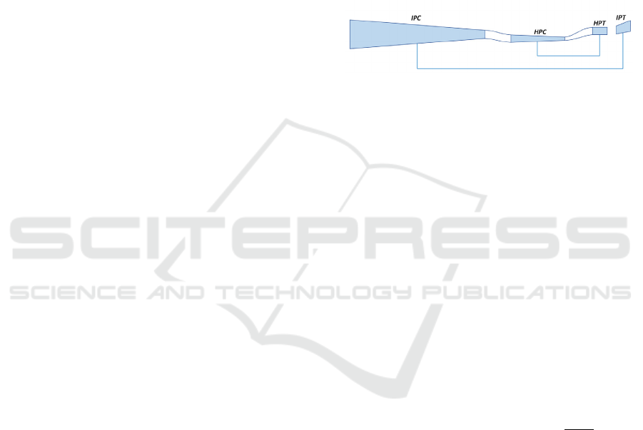
The FP scheme of a two-shaft CE in the
meridional plane with the designation of
characteristic sections is shown in Figure 1.
The distribution of pressure ratio 𝜋
∗
and
specific work 𝐿
of the entire core engine by
compressor cascades is proposed to be carried out
focusing on the rational distribution of specific work
and the degree of pressure decrease in the CE between
the HPT and IPT, Grigor'ev, V. (2009). It should be
taken into account that these turbines at cruise mode
operate at the loading parameter 𝑌
∗
≈𝑌
∗
≈ 0.55
and reactivity degree 𝜌
= 0.40-0.45.
Figure 1: Flow path scheme of a two-shaft core engine.
Under these conditions, it is necessary to achieve
such a loading of the HPT and IPT that no zones with
increased supersonic flow velocities and,
consequently, wave losses would appear in their flow
path at the middle diameter. In this case, it is desirable
that the values of the reduced isoentropic flow
velocities both at the outlet of the stator blade (SB) in
absolute motion 𝜆
, and at the outlet of the rotor
wheel (RW) in relative motion 𝜆
would be
approximately the same in the HPT and IPT.
In contrast to the previously proposed variants
(Grigor'ev, V. (2009)), it is recommended to
determine the rational distribution of specific work
between intermediate and high-pressure cascades in
accordance with the algorithm shown in Figure 2.
As initial data for the first approximation, the
values of parameters from thermodynamic
calculation of the whole engine at cruise mode and
the same values of pressure ratio in IPC 𝜋
∗
and
HPC 𝜋
∗
are taken: 𝜋
∗
=𝜋
∗
=
𝜋
∗
.
According to the standard methods, using the
initial data for both the HPT and IPT, the reduced
isentropic flow velocities at the SB outlet in absolute
motion 𝜆
and at the RW outlet in relative motion
𝜆
of the HPT and IPT at the middle diameter are
determined (Figure 2).
After that, the values of the corresponding
velocities in the HPT and IPT are compared with each
other. If at practically identical values of 𝜌
of HPT and IPT the value of
relative difference
𝜆
−𝜆
𝜆
⁄
or
𝜆
−𝜆
𝜆
⁄
will be more than
3%, then the value of 𝜋
∗
at the next iteration of
SIMULTECH 2024 - 14th International Conference on Simulation and Modeling Methodologies, Technologies and Applications
224
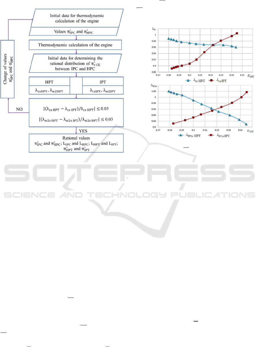
calculation decreases. And if these values are less
than minus 3%, then 𝜋
∗
increases.
Figure 2: Algorithm for determining the rational
distribution of specific work between intermediate and
high-pressure cascades.
At the expense of some adjustment of the values
𝜌
of HPT and IPT in the above ranges, it is
reasonable to ensure approximate equality of the
reduced velocities 𝜆
and 𝜆
, as well as
λ𝜆
and 𝜆
in order to reduce the wave
losses in the turbine flow path.
When the conditions
|
𝜆
−𝜆
𝜆
⁄|
0.03 and
|
𝜆
−𝜆
𝜆
⁄|
0.03 are
reached, the final values of pressure ratios 𝜋
∗
and
𝜋
∗
, specific works 𝐿
, 𝐿
, 𝐿
and 𝐿
, as
well as the pressure decrease ratios in the HPT
𝜋
∗
and IPT 𝜋
∗
are recorded.
The results of determining the reduced isoentropic
flow velocities at the outlet from the SB and RW of
high and intermediate pressure turbines at successive
iterations of the calculation of a promising aviation
GTE at different values of 𝜋
∗
=𝜋
∗
𝜋
К
∗
⁄
are
presented in Figure 3.
As can be seen from the presented dependences,
the 𝜆
≈𝜆
and 𝜆
≈𝜆
equalities occur approximately at 𝜋
∗
= 0.225 and
𝜋
∗
= 0.145. At these values of relative pressure
ratios in IPC and HPC, the values of relative specific
work are 𝐿
=𝐿
𝐿
⁄
= 0.43 and 𝐿
=
𝐿
𝐿
⁄
=0.57. Relative pressure decrease ratios in
HPT are 𝜋
∗
=𝜋
∗
𝜋
∗
⁄
= 0.399 and in IPT
𝜋
∗
=𝜋
∗
𝜋
Т
∗
⁄
=0.363 ( 𝜋
∗
is the total
pressure decrease ratio in CE turbines).
a
b
Figure 3: Dependences of the reduced isentropic
flow velocities on 𝜋
∗
: a - at the SB outlet;
b - at the RW outlet.
4 SELECTION OF THE HP
CASCADE SPEED AND
FLOWPATH GEOMETRY
Assignment of the rotational speed n of the cascade
rotor at the design cruise mode of engine operation
and determination of the main design-geometric
parameters of the TM of the cascade has a
determining influence on the efficiency of its
operation and the FP dimensions. Basically, as cited
in Krupenich, I. (2006), the following system of
equations is used to determine the circumferential
velocities at the TM middle diameter, the rotational
speed of the cascade, as well as its main design and
geometrical parameters (stage number of the cascade
compressor and TM middle diameters) at the design
mode:
𝑈
=𝜋𝐷
𝑛
60
⁄
;
𝑈
=𝜋𝐷
𝑛
60
⁄
;
𝐿
=𝑈
𝜂
∗
2
𝑌
∗
⁄
;
𝐿
=𝑧
𝐻
𝑈
𝑈
- circumferential velocity at the middle
diameter of the compressor cascade;
𝐷
- middle diameter of the compressor cascade;
Algorithm of Forming the Appearance of the Flow Path of Turbomachinery of Two-Shaft Aircraft Engine Core
225
𝑛
- rotor speed of the compressor cascade;
𝑈
- circumferential velocity at the middle
diameter of the turbine cascade;
𝐷
- middle diameter of the turbine cascade;
𝑛
- rotor speed of the turbine cascade;
𝐿
- specific work of the turbine stage;
𝜂
∗
- efficiency of the turbine stage;
𝑌
∗
- turbine stage loading parameter;
𝐿
- specific work of the compressor cascade;
𝑧
- stage number of compressor cascade;
𝐻
- average coefficient of expended head at the
middle diameter.
This system has four equations and eight
unknowns ( 𝑈
, 𝐷
, 𝑈
, 𝐷
, 𝑌
∗
,
𝐻
, 𝑧
and 𝑛
= 𝑛
= 𝑛 ). The values of the
parameters 𝐿
, 𝐿
and 𝜂
∗
are known from the
thermodynamic calculation of the whole engine and
having performed the previous step of the calculation.
Thus, in the above system of equations, the four
parameters of the equations must be either given or
otherwise determined.
According to Bakulev, V. (2003) the value of the
loading parameter 𝑌
∗
is usually set close to the
optimum in the range of 0.50-0.60, the value of
𝐻
is in the range of 0.30-0.40.
The smallest value of the middle diameter of the
turbine stage is limited for RW strength
considerations by the following ratio
𝐷
/ℎ
=𝑈
𝜀
,
𝑈
- circumferential velocity of
turbine RW at the middle diameter at take-off mode;
ℎ
- blades height at the outlet of the turbine RW;
𝜀
- the largest permissible stress
parameter at take-off mode, the value of which is
roughly in the range of (18…20)∙10
3
m
2
/s
2
for HPT,
and for IPT is in the range of (23…25)∙10
3
m
2
/s
2
,
Grigor'ev, V. (2009).
The middle diameter of the compressor cascade is
determined either from the condition of achieving the
highest permissible reduced circumferential velocity
at the periphery of the first stage RW 𝑈
ℎ
(430-450 m/s for IPC and 330-350 m/s for HPC), or
from the condition of limiting the minimum
permissible blades height at the compressor cascade
outlet ℎ
= 15-20 mm, Bakulev, V. (2003).
Taking into account the mentioned restrictions
and FP areas in characteristic sections of
turbomachinery calculated using the equation of
continuity, the algorithm of finding the main
geometrical parameters of turbomachinery FP in the
meridional plane and determination of their rotation
frequencies is compiled.
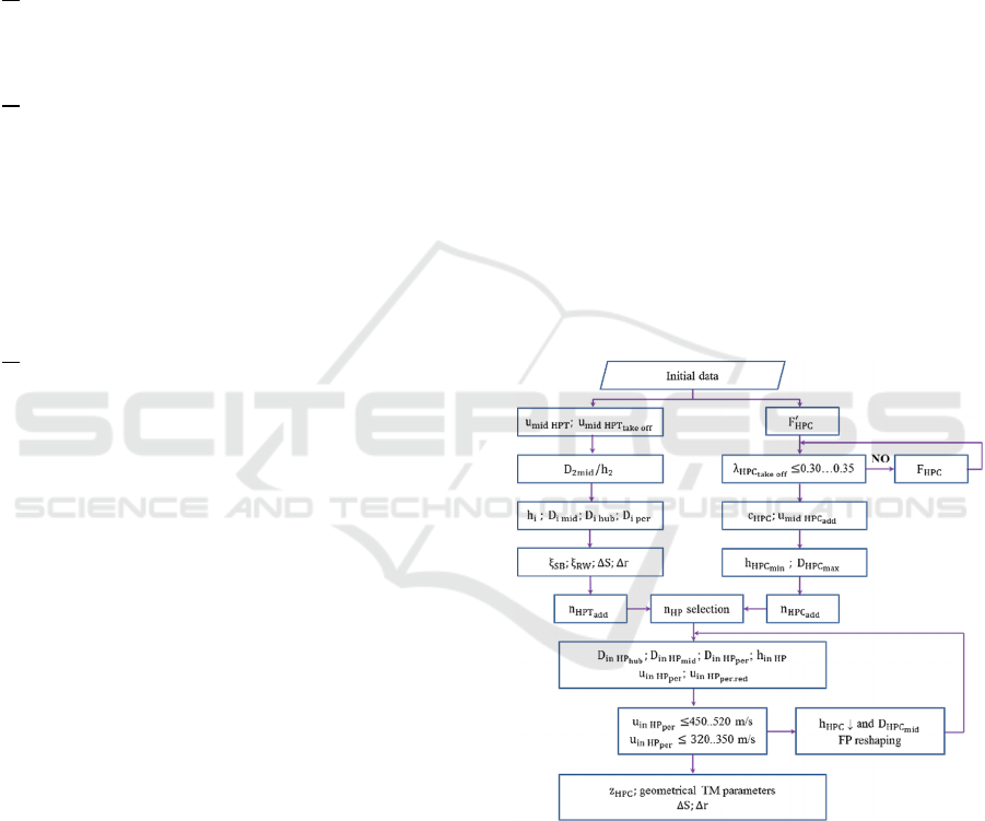
The choice of rotor speed 𝑛
and determination
of the main structural and geometrical parameters of
the HP cascade in the meridional plane is carried out
using the algorithm, which has two parallel branches
(Figure 4):
- a branch defining the highest permissible
rotational speed of the HPT 𝑛
in terms of
strength (left column of the algorithm);
- a branch defining the highest permissible
rotational speed 𝑛
in terms of the efficiency of
the working process of the last HPC stage (right
column of the algorithm).
As initial data, we take the parameters whose
values were found in the thermodynamic calculation
of the engine at cruise and take-off modes, as well as
in determining the rational distribution of specific
work between the cascades of core engine at the first
step of the calculation. The initial data includes also
the equivalent engine operating time at take-off mode
𝜏
, as well as the density of the rotor blade
material 𝜌
and the Larson-Miller diagram
corresponding to this material.
Figure 4: Algorithm for determining 𝑛
and structural and
geometrical parameters of HPC and HPT.
Based on the initial data, when determining the
value of 𝑛
, the circumferential velocities at
the RW middle diameter at cruise and take-off modes
and the ratio of the middle diameter to the height of
the blades at the turbine outlet 𝐷
ℎ
⁄
are initially
determined. Then the blade heights ℎ
and diameters
𝐷
, 𝐷
, 𝐷
of the flow path in characteristic
sections are determined (index i denotes the number
SIMULTECH 2024 - 14th International Conference on Simulation and Modeling Methodologies, Technologies and Applications
226

of the characteristic section), as well as, in accordance
with the known recommendations cited in Belousov,
A. (2006), the values of the width of the blade row of
the stator blade 𝑆
and rotor wheel 𝑆
, axial ΔS and
radial Δr clearance.
As a result, the permissible RW rotational speed
of the HPT at cruise mode is calculated as 𝑛
=
60𝑈
𝜋𝐷
⁄
in terms of the strength of the
rotor blades.
When determining the permissible highest
rotational speed 𝑛
in terms of the working
process efficiency of the last HPC stage, we find in
the first approximation the cross-sectional area at the
HPC outlet 𝐹
′
and the corresponding reduced flow
velocity at take-off mode 𝜆
, which value
should not exceed 0.30-0.35, Bakulev, V. (2003). If
this condition is not fulfilled, the value of the area at
the outlet of the HPC is corrected (Figure 4).
After that, the flow velocity at the outlet of the
HPC С
is found at cruise mode. Then, the largest
permissible circumferential velocity at the middle
diameter of the last RW stage is determined as
𝑈
= С
/С
. Where С
= 0.39-
0.41 is the range of selection of the smallest
permissible value of the flow rate coefficient at the
outlet of the last compressor stage, recommended in
terms of an acceptable degree of flow diffusivity in
the blade passage of the RW and guided vane of the
last stage.
The circumferential velocity 𝑈
is
related to the middle diameter at the outlet of the last
stage of the HPC 𝐷
and the rotor speed of the
HPC 𝑛
by the expression 𝑈
=
𝜋𝐷
𝑛
60
⁄
. By specifying the diameter
𝐷
, from the last expression, the rotational
speed 𝑛
, that provides the highest
circumferential velocity 𝑈
, can be
obtained.
In this case two variants are possible:
- If 𝑛
is larger than 𝑛
, then
𝑛
is taken as the shaft rotational speed of the
HP cascade 𝑛
;
- if 𝑛
is less than 𝑛
, then 𝑛
is taken as the shaft rotational speed of the HP cascade
𝑛
.
As the GTE design experience of the latest engine
generations shows, Bakulev, V. (2003), the second
variant of events turns out to be practically
impossible. The point is that even at the largest
middle diameter at the HPC outlet 𝐷
,
which is calculated by the formula: 𝐷
=
𝐹
𝜋ℎ
⁄
, where the smallest blade height of
the last HPC guided vane ℎ
is taken not less
than 15-20 mm, Bakulev, V. (2003), the value
𝑛
=60𝑈
𝜋𝐷
⁄
appears
to be higher than the rotational speed 𝑛
.
The performed example calculation confirmed
this trend. The value of 𝑛
obtained at
ℎ
= 21 mm and 𝐷
was found to be
greater than 𝑛
.
After that, the shape of the HPC flow path in the
meridional plane is selected and such parameters at
its inlet as the diameters 𝐷
, 𝐷
,
𝐷
and blade height ℎ
, the
circumferential velocity at the RW periphery of first
stage 𝑈
and the corresponding reduced
circumferential velocity 𝑈
are
determined.
At the same time, there is a check of compliance
with the restrictions on the values of these last
velocities. Namely, the velocity 𝑈
, based on
strength conditions, should be less than 450-520 m/s,
and the velocity 𝑈
for gas dynamic
reasons should not exceed 320-350 m/s.
Otherwise, it is necessary to increase ℎ
and
decrease 𝐷
or change the FP shape of the HPC
in the meridional plane and correct the calculation,
starting with determination of geometrical parameters
at the HPC inlet (Figure 4).
After that, according to the standard
methodology, the HPC stage number 𝑧
is
determined and geometrical parameters of each blade
row (diameters, height and width) characterising it in
the meridional plane are calculated, and axial ΔS and
radial Δr clearances are selected.
5 DESIGN OF A INTRMIDEATE
PRESSURE CASCADE
It is reasonable to estimate the main parameters of the
flow path of the intermediate-pressure cascade in the
same sequence as the parameters of the high-pressure
cascade, but taking into account a number of
peculiarities.
Firstly, since the middle diameter at the outlet of
the IPT rotor wheel 𝐷
is significantly larger
than the same diameter at the HPT outlet 𝐷
,
the intermediate pressure turbine should be made
diagonal. This makes it possible to exclude the
transition duct between the HPT and IPT.
Secondly, for design reasons related to the
necessity to place the rotor of the low-pressure
cascade inside the shaft of the intermediate-pressure
cascade, it is required to provide the hub diameter of
the IPC larger than the minimum permissible value.
Algorithm of Forming the Appearance of the Flow Path of Turbomachinery of Two-Shaft Aircraft Engine Core
227

Thirdly, it should be taken into account that the
circumferential velocity at the RW periphery of the
first stage of IPC 𝑈
in terms of strength is
limited by the value of 450-500 m/s, Belousov, A.
(2006), and the reduced circumferential velocity
𝑈
in the same section is limited by the
values of 430-450 m/s for gas-dynamic
considerations.
Fourthly, as well as in the case of high-pressure
cascade, the permissible IPC rotational speed
𝑛
is usually higher than the permissible IPT
rotational speed 𝑛
. Therefore, 𝑛
is
taken as the rotational speed of the IP shaft 𝑛
, and
in order to maintain the accepted value of the
circumferential velocity 𝑈
and, possibly,
not to increase the IPC stage number, it is reasonable
to increase the middle diameter of the IPC by a factor
of 𝑛
𝑛
⁄
.
The increase of the middle diameter
𝐷
leads to the necessity of the transition duct
between IPC and HPC.
For the considered example, the flow path scheme
of the turbomachinery of a two-shaft core engine with
observance of proportions in axial and radial
directions is shown in Figure 1.
6 CONCLUSIONS
The developed algorithm of the flow path design
formation of the turbomachinery of a two-shaft core
engine makes it possible to find rational proportions
of pressure ratios of IPC and HPC, as well as pressure
ratios of HPT and IPT, using the reduced flow
velocities at the outlet of the turbine blade row as
rationality criteria.
It makes it possible to select the rotational speed
of intermediate and high-pressure cascades taking
into account strength and gas dynamic limitations, as
well as to determine the main structural and
geometric parameters of the core engine
turbomachinery in the meridional plane.
To reduce the axial dimensions of the turbine part
of the core engine a diagonal-type IPT can be used.
ACKNOWLEDGMENTS
The study was supported by the Russian Science
Foundation grant No. 23-79-10266,
https://rscf.ru/project/23-79-10266/
REFERENCES
Kholshevnikov, K. (1965). Coordination of Compressor
and Turbine Parameters in Aviation Gas Turbine
Engines (in Russian). Moscow, Mashinostroenie.
Bakulev, V. (2003). Theory, Calculation and Design of
Aviation Engines and Power Plants (in Russian).
Moscow: MAI Publishing House.
Bochkaryov, S., Kuzmichev, V. (2005). Theory,
Calculation and Design of Aviation Engines and Power
Plants (in Russian). Moscow, Mashinostroenie.
3
rd
Book.
Grigor'ev, V. (2009). Parameter Selection and Thermal and
Gas Dynamic Calculations of Aviation Gas Turbine
Engines (in Russian). Samara: Samara State Aerospace
University Press.
Krupenich, I. (2006). Variant Automated Design of the
Flow Path of the Turbocompressor of Aviation GTE (in
Russian). Samara: Vestnik SGAU.
Belousov, A. (2006). Design Thermal and Gas-Dynamic
Calculation of the Basic Parameters of Aviation Blade
Machineries (in Russian). Samara: Samara State
Aerospace University Press.
SIMULTECH 2024 - 14th International Conference on Simulation and Modeling Methodologies, Technologies and Applications
228
