
An Extension of Orbslam for Mobile Robot Using Lidar and Monocular
Camera Data for SLAM Without Odometry
Rodrigo Lucas Santos
a
, Mateus Coelho Silva
b
and Ricardo A. R. Oliveira
c
Departmento de Computac¸
˜
ao - DECOM, Universidade Federal de Ouro Preto - UFOP, Ouro Preto, Brazil
Keywords:
SLAM, Mobile Autonomous Robot, Data Fusion, RPLIDAR, RGB Camera.
Abstract:
Mobile autonomous robots require accurate maps to navigate and make informed decisions in real-time. The
SLAM (Simultaneous Localization and Mapping) technique allows robots to build maps while they move.
However, SLAM can be challenging in complex or dynamic environments. This study presents a mobile
autonomous robot named Scramble, which uses SLAM based on the fusion of data from two sensors: a
RPLIDAR A1m8 LiDAR and an RGB camera. How to improve the accuracy of mapping, trajectory planning,
and obstacle detection of mobile autonomous robots using data fusion? In this paper, we show that the fusion
of visual and depth data significantly improves the accuracy of mapping, trajectory planning, and obstacle
detection of mobile autonomous robots. This study contributes to the advancement of autonomous robot
navigation by introducing a data-fusion-based approach to SLAM. Mobile autonomous robots are used in a
variety of applications, including package delivery, cleaning, and inspection. The development of more robust
and accurate SLAM algorithms is essential for the use of these robots in challenging environments.
1 INTRODUCTION
The era of automation is advancing exponentially,
transforming fundamental sectors such as logistics,
space exploration, and public safety. In this rapidly
evolving scenario, autonomous navigation emerges as
one of the most significant and transformative chal-
lenges in the field of robotics, with great revolution-
ary power especially in environments that challenge
the reliability of traditional navigation systems, such
as GPS and odometry, which often encounter limi-
tations in complex and dynamic scenarios (Grisetti
et al., 2007).
At the heart of this revolution, Simultaneous Lo-
calization and Mapping (SLAM) represents a critical
technological innovation, enabling robots to achieve
unprecedented autonomy. SLAM is not just about
mapping the unknown, but above all, it is the syner-
gistic fusion of sensor data to shape an understanding
of spatial environment in real time, where each mea-
surement and data contributes to the global position
of a mobile robot’s location.
The Visual SLAM strategy stands out for its abil-
a
https://orcid.org/0000-0003-3795-9218
b
https://orcid.org/0000-0003-3717-1906
c
https://orcid.org/0000-0001-5167-1523
ity to work under limited illumination and produce
high-definition maps. However, it faces environmen-
tal adversities such as shadows and reflections, which
can distort the perceived reality (Cadena et al., 2016).
By adding depth to the equation with sensors like 3D
LIDAR, we can obtain precise details about the world
around the robot. Although quite effective, the com-
plexity and cost associated with these sensors often
make them inaccessible for generalized applications
(Weiss and Biber, 2011). A more viable solution, 2D
LiDAR, offers an accessible alternative, providing ac-
curate measurements of angle and distance in a Carte-
sian plane.
Among the technologies highlighted in the liter-
ature, ORB-SLAM emerges with remarkable perfor-
mance, especially when compared to other monocu-
lar SLAM approaches (Zong et al., 2017) (Mur-Artal
and Tard
´
os, 2016). This system not only exemplifies
precise execution of real-time localization and map-
ping but also extends its applicability from indoor to
outdoor environments, overcoming the limitations of
traditional SLAM approaches.
In response to the call for significant advances
in this field, this study presents a new extension for
Monocular ORB-SLAM. It differentiates itself by in-
tegrating an innovative sensor, the rpLIDAR 2D, cre-
ating a hybrid methodology that capitalizes on the fu-
Santos, R., Silva, M. and Oliveira, R.
An Extension of Orbslam for Mobile Robot Using Lidar and Monocular Camera Data for SLAM Without Odometry.
DOI: 10.5220/0012736500003690
Paper published under CC license (CC BY-NC-ND 4.0)
In Proceedings of the 26th International Conference on Enterprise Information Systems (ICEIS 2024) - Volume 1, pages 943-954
ISBN: 978-989-758-692-7; ISSN: 2184-4992
Proceedings Copyright © 2024 by SCITEPRESS – Science and Technology Publications, Lda.
943
sion of data from a LiDAR scanner and an RGB cam-
era. This synergy aims to improve the precision and
robustness of SLAM, tailoring it to face more com-
plex and dynamic environments.
To validate the proposed method, an autonomous
mobile robot was developed, equipped with a
SLAMTEC A1M8 LiDAR sensor and a Logitech
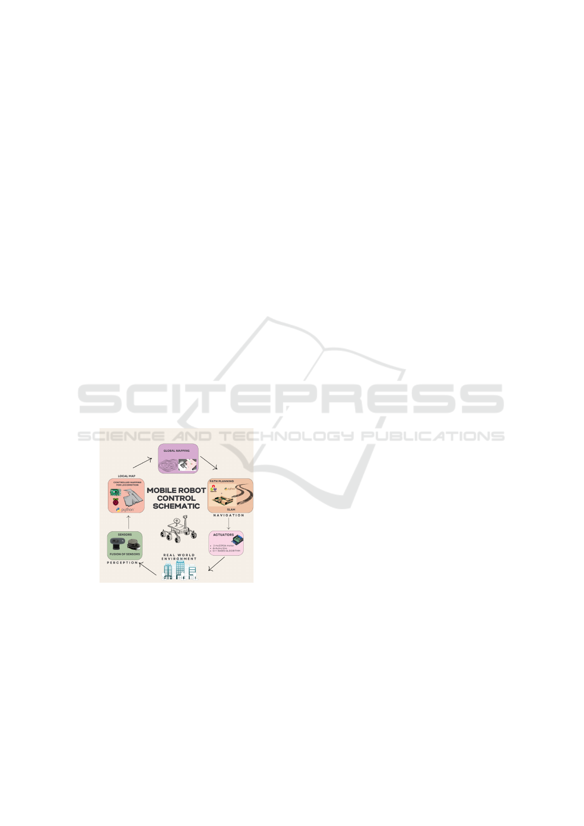
C270 webcam. Figure 1 represents the schematic
control of the developed mobile robot. Data fusion
is carried out by an algorithm capable of merging and
correlating information captured by both the LiDAR
and the camera. This data fusion process plays a cru-
cial role in obtaining a more comprehensive and ac-
curate representation of the robot’s surrounding envi-
ronment.
The authenticity of the proposed method was ver-
ified through the development and testing of an au-
tonomous mobile robot, demonstrating that the data
fusion approach surpasses the limitations of method-
ologies based on singular sensors.
This contribution is a step forward in the develop-
ment of autonomous navigation, highlighting how the
integration of visual and depth data can unlock new
horizons for mapping, trajectory planning, and more
precise and reliable obstacle detection. This study not
only propels the field of autonomous robotics but also
paves the way for an era of applicable innovations in
a diverse and challenging range of operational envi-
ronments.
Figure 1: Mobile Robot Control Schematic.
2 THEORETICAL REFERENCES
2.1 Autonomous Mobile Robots
The essence of mobile robots lies in the concept of
requiring minimal or no human intervention during
their locomotion and navigation operations. These
devices can generate symbols through interaction
with the external and/or internal environment, at-
tributing unique meaning to each element. In indoor
settings, mobile robots often rely on a combination of
sensors, including floor plans, sonar-based localiza-
tion systems, and inertial measurement units (IMUs).
These sensors play a crucial role in enabling the robot
to create an internal representation of its surround-
ings, thereby ensuring its effective and autonomous
operation.
To ensure adequate performance, the construction
of such robots requires the integration of several sen-
sors, the combination of which provides an accurate
internal representation of the environment. Location
plays a crucial role in the operation of an AMR, being
essential for mapping the environment and effectively
controlling its navigation.
However, noisy and/or confined environments
present significant challenges in obtaining location,
especially when using sensors such as GPS to ob-
tain the device’s position and orientation. The strat-
egy of obtaining the position and orientation of the
device, known as odometry, has the main objective of
developing a mathematical model that represents the
robot’s movements over time, resulting in a model of
the device’s current position and orientation. Further-
more, building maps is an essential task for the auton-
omy of mobile robots and is often closely linked to
the robot’s localization difficulties.
2.2 Visual Odometry
Visual odometry is a method for estimating the po-
sition and orientation of vehicles from camera im-
ages(Barducci and Scaramuzza, 2018). This method
is based on detecting visual features, such as land-
marks or objects, in successive images. Based on
the correspondence between these characteristics, it
is possible to estimate the vehicle’s movement. The
main objective of visual odometry is local consistency
and continuous estimation of vehicle trajectory and
poses. This means that the method must be able to ac-
curately estimate vehicle movement over time, even
in environments with changing lighting or obstruc-
tions.
The visual odometry process can be divided into
four main steps:
1. Detection of visual characteristics: in this step,
visual characteristics are identified in successive
images. These features can be landmarks, lines,
or other objects that are easily tracked over time.
2. Feature tracking: In this step, the identified vi-
sual features are tracked across successive images.
ICEIS 2024 - 26th International Conference on Enterprise Information Systems
944

This is done by comparing the features of an im-
age with the features of previous images.
3. Motion estimation: in this step, the vehicle move-
ment is estimated based on the correspondence
between the visual characteristics tracked.
4. Position update: in this step, the vehicle position
is updated based on the information obtained in
the previous step.
Visual odometry is a promising technique for esti-
mating the position and orientation of vehicles(Cheng
et al., 2022). However, this method presents some
challenges, such as the accumulation of errors over
time and the difficulty of adapting to new environ-
ments.
2.3 SLAM - Simultaneous Localization
and Mapping
Localization of an Autonomous Mobile Robot
(AMR) plays a crucial role in its operation, as it is
essential for performing environment mapping and
controlling its navigation. However, dynamic and/or
confined environments pose significant challenges in
obtaining localization, especially when using sensors
such as GPS to obtain the device’s position and orien-
tation. The strategy of obtaining the device’s position
and orientation, known as odometry, has as its main
objective to develop a mathematical model that repre-
sents the robot’s movements over time, resulting in a
model of the device’s current position and orientation
(Dudek and Jenkin, 2010). In addition, map building
is an essential task for the autonomy of mobile robots
and is often closely linked to the robot’s localization
difficulties(da Cruz J
´
unior et al., 2021).
SLAM is a robotic process that addresses two es-
sential questions: ”Where am I?” and ”What is the
environment around me?” Addressing these questions
simultaneously represents a significant challenge due
to the complexity of the environment and the possi-
bility of new questions arising during the execution of
SLAM. SLAM algorithms have been developed to ad-
dress the challenge of mapping and localization, vary-
ing in the sensors and mathematical models used.
In general, sensors such as cameras, LiDAR,
radar, GNSS, and IMU are employed to collect infor-
mation from the environment. This data is processed
through optimization problems to solve the SLAM
problem(Kurt-Yavuz and Yavuz, 2012). The integra-
tion of multiple sensors into a single framework has
shown promise in robotics, especially in the naviga-
tion of autonomous vehicles. Although there are sev-
eral solutions in the literature that improve existing
techniques, only a few of them adopt truly innova-
tive approaches, such as data fusion, which combines
information from multiple sensors to increase the ac-
curacy and reliability of SLAM.
In summary, SLAM plays a crucial role in robotics
by addressing simultaneously localization and map-
ping in challenging environments, with different al-
gorithms and techniques aiming to improve the per-
formance and accuracy of this process.
3 RELATED WORKS
In (Ni et al., 2022) an improved adaptive ORB-SLAM
method with monocular vision in dynamic environ-
ments for robots is proposed. This method is capa-
ble of dynamically adapting to the presence of mov-
ing and dynamic objects, adjusting the robustness of
the visual characteristics used for SLAM. As a re-
sult, there is a significant improvement in the accu-
racy and reliability of the system in dynamic environ-
ments, which makes it attractive in real environments.
Additionally, in (Li et al., 2023) a method capa-
ble of performing a dense reconstruction of substa-
tion rooms using LSD (Large-Scale Direct) is pro-
posed. LSD SLAM is a SLAM method that uses di-
rect information from images to map the environment
and locate the mobile agent. This study aims to re-
construct internal substation environments in detail,
which are complex environments and require high
mapping accuracy to guarantee safety and efficiency
when implementing LSD SLAM. The experimental
results demonstrate the effectiveness of the method in
dense reconstruction of substation rooms, providing
accurate maps that can be useful for various practical
applications such as maintenance planning and safety
inspection. It is worth mentioning that this system
requires high processing power and very high speed
GPUs for everything to occur as promised.
Although reliable and robust, the mentioned Vi-
sual SLAM techniques assume that environments
are static. However, in (Soares et al., 2022), a
new VISUAL SLAM method specially developed
for crowded human environments is introduced, em-
ploying person detection. In the literature, several
works address the implementation of SLAM in mo-
bile robots based on Raspberry Pi. One of these works
is (Serrata et al., 2017), which implements SLAM
technology using a low-cost Pixy camera, a robot
kit with an L298N motor board, and a Raspberry Pi
”V2.0”. The system was able to identify an average of
75% of reference points when detecting corners and
corridors, with an average power consumption of 1.14
W.
Another relevant work is (Miranto et al., 2019),
An Extension of Orbslam for Mobile Robot Using Lidar and Monocular Camera Data for SLAM Without Odometry
945
which implements the Orbslam (Mur-Artal et al.,
2015) method with a monocular camera via a web-
cam. However, the system is integrated and depen-
dent on ROS (Robot Operating System) although it
is based on Raspberry Pi. Using the ORBSLAM
method, it is possible to detect objects of size 31.5x56
cm at a distance of 70 cm, with an error value of
1.21% and an accuracy value of 98.79%. These
works show that SLAM can be effectively deployed
on Raspberry Pi-based mobile robots. However, there
is still room for improvement, such as increasing ob-
ject detection accuracy and reducing power consump-
tion.
Toroslu and Do
˘
gan (2018)(Toroslu and Do
˘
gan,
2018) proposed a sensor fusion method for au-
tonomous vehicles that uses a combination of ultra-
sonic, optical, and IMU sensors. The method was im-
plemented on a mobile robot with two motors, and
the results showed that the method is capable of es-
timating the position and orientation of the robot ac-
curately in environments with changes in lighting and
obstructions. To achieve this, it uses a sensor fusion
algorithm based on a Kalman filter, which is not al-
ways so simple to configure. Additionally, they used
an optical encoder instead of the accelerometer in an
attempt to avoid noise and measurement error issues.
Using the Pygame library, they calculated the coordi-
nates and location of objects detected during naviga-
tion.
4 METHODOLOGY
In this study, we introduce an innovative approach for
performing SLAM (Simultaneous Localization and
Mapping) using two main visual sensors: a Log-
itech Webcam and a 2D RPLIDAR model A1M8
from SLAMTEC. To validate our experiments, we de-
veloped an autonomous mobile robot, the details of
which will be thoroughly presented in the experimen-
tal results section. The methodology adopted is di-
vided into four distinct sections.
In the first section, we will address the robot’s
perception methods and the sensors involved in this
stage. The second section will discuss the robot’s
cognition model, while the third section will focus on
robot navigation, covering the concepts of mapping,
localization, and the SLAM method that we devel-
oped specifically for Robotic Navigation, the central
object of this research. Finally, the fourth section will
explore the proposed scenario for locomotion and ex-
periments, the results of which will be presented in
the subsequent section of this work.
4.1 Perception Methods
In the field of robotics, especially for autonomous
mobile robots, perception plays a crucial role, en-
abling the robot to acquire self-awareness and under-
stand the external context in which it operates (Ran
et al., 2021). The ability of a robot to navigate au-
tonomously depends significantly on the perception’s
capability to accurately gather information and fea-
tures from the environment, allowing the robot to
comprehend its surrounding area. Typically, this per-
ception is achieved through the combination of high-
resolution sensors and efficient algorithms to extract
information from these sensors. In the scope of this
work, to accomplish the robot’s perception stage, we
employed two specific sensors: a Slamtec YDLIDAR
A1M8 and a Logitech C270 webcam, respectively.
The main objective of the camera implemented in
this work is to recognize and extract characteristics of
the environment and perceive fixed locations through
predetermined tags. This perception is fundamental
for decision-making in controlling the robot’s move-
ment. These objectives highlight the importance of
the camera as an essential component for perception
and decision-making in robotic environments, empha-
sizing its fundamental role in the efficiency and safety
of robotic operations.
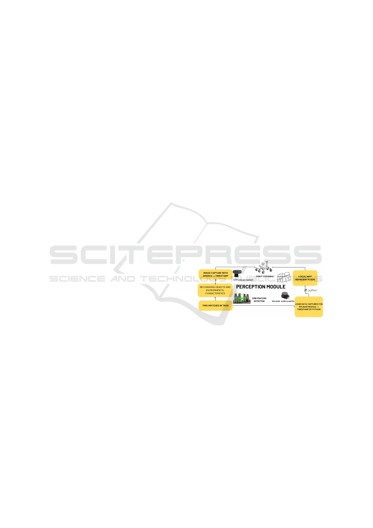
Figure 2: Robot Perception Module.
Additionally, computer vision algorithms written
in Python were implemented in the perception module
so that the camera and lidar recognize real-world data
and represent it in the robot’s world. Figure 2 presents
the basic scheme of the robot perception module pro-
posed in this work.
4.1.1 Camera Data Collection and Processing
To capture and process data from the camera, we used
a webcam from the manufacturer Logitech, model
C270 RGB, connected to the Raspberry Pi model
3B. The images are processed using Python and the
OpenCV library (Open Source Computer Vision Li-
brary), an open-source computer vision tool that of-
fers an extensive variety of features (
ˇ
Culjak et al.,
2012), such as facial recognition, motion detection,
ICEIS 2024 - 26th International Conference on Enterprise Information Systems
946

patterns, calibration of the camera, image segmenta-
tion and feature detection in images.
The algorithm operates as follows: the robot is ini-
tially positioned at an arbitrary point within a maze,
as detailed in section 4.3 of this work. During its tra-
jectory, the robot avoids obstacles and collisions with
the walls of the maze. Eight predefined images were
strategically placed throughout the environment, re-
ferred to in this study as ”tags”. The robot moves
through the maze, constantly seeking the greatest free
distance, validated by the LIDAR sensor. Simul-
taneously, the camera module, which integrates the
robot’s perception, captures videos using the OpenCV
library.
The identification of ”tags” is carried out through
a combination of the ORB (Rublee et al., 2011) and
RANSAC (Cantzler, 1981) algorithms. These algo-
rithms allow the robot to perceive and identify itself
as ”tags” in the environment at a fixed distance of
30 cm, employing descriptor point recognition tech-
niques and correspondences between images.
When the robot finds one of these ”tags”, it locates
its position in the environment. After identifying the
”tag”, the robot makes a soft stop, captures an im-
age of the environment with the camera, and adds a
stamp containing temporal information, such as data
and time. Automatically, the robot starts mapping
around the current position using the LIDAR module
within a 5-second interval. After completing this lo-
cal mapping, the robot continues its navigation in the
maze, avoiding obstacles, until it finds another ”tag”
when it repeats the local mapping process.
4.1.2 Data with Lidar
The Lidar is a sensor that measures distances and an-
gles using laser light (Ashraf et al., 2017). Compris-
ing a laser emitted and reflected by surrounding ob-
jects, a detector measuring the time taken for the light
to return, and a data processing system that, utilizing
the speed of light, calculates the distance to the ob-
ject. This system can generate a 2D representation of
the environment using the collected data of distance
and angle, respectively. The data processing system
combines the distance and angle information to cre-
ate a two-dimensional environment representation.
The device used in this study is the RPLIDAR
model A1M8 from Yahboom. Its measurement fre-
quency ranges from 8000 to 32000 times per second,
and its scanning frequency varies from 7 to 16 Hz,
easily adjustable by the operator. Widely employed
in robotics for mapping intricate environments, the
RPLIDAR is capable of creating high-precision grid
maps (Son et al., 2021). Each measurement per-
formed by the RPLIDAR involves a 360
o
rotation
emitting a laser that traverses the surroundings until
encountering an obstacle, immediately returning dis-
tance and angle information of the detected object.
Data reading is conducted through the Python lan-
guage using the RPLIDAR module, openly avail-
able on GitHub (Skoltech Robotics, 2024). Within
the robot’s perception module, a specific submodule
is dedicated to capturing and interpreting data from
the lidar sensor. In the scope of this work, the li-
dar performs two fundamental functions: it obtains
distance information from obstacles to improve the
robot’s navigation and performs local mapping after
the camera module identifies tags positioned arbitrar-
ily throughout a maze.
The robot navigates through an environment,
avoiding obstacles identified by the lidar, until it lo-
cates one of the tags positioned along the path. Detec-
tion is carried out by the camera, which, upon identi-
fying the tags, immediately activates the robot’s con-
trol module. The cart then begins to map the location
using the lidar, located on the top of the robot. The li-
dar records the points collected in its current position
at 5-second intervals, allowing the robot to accurately
capture information on the distances and angles of ob-
jects in its surroundings, limited to a maximum radius
of 12 meters. After 5 seconds, the robot resumes navi-
gating the environment, avoiding obstacles, and, upon
finding another tag, interrupts to carry out local map-
ping with the lidar module, repeating the process dur-
ing navigation.
The data collected by the lidar in each mapping is
stored in a text file (.txt), where each line represents
a measurement taken by the lidar, including angle in-
formation in degrees and distance in millimeters. On
each measurement (line), a timestamp is added to en-
able accurate fusion of the lidar data with the camera
data. This timestamp is crucial to accurately synchro-
nizing data.
4.2 Cognition Model
As the robot is exposed to the environment, it col-
lects and accumulates data related to its rotation, al-
lowing you to familiarize yourself with the objects
around you progressively. This increasing familiarity
allows the robot to consider previously visited loca-
tions without the need for long processing time.
The robot is essentially composed of two dis-
tinct parts: the mechanical structure and the control
module. The control module covers data perception
through sensors, processing, and cognitive naviga-
tion. This approach allows the robot to use the re-
sources of its mechanical structure to move intelli-
gently, avoiding collisions and accidents. After pro-
An Extension of Orbslam for Mobile Robot Using Lidar and Monocular Camera Data for SLAM Without Odometry
947
cessing and interpreting the data by the perception
module, cognitive education has two main objectives:
avoiding obstacles and optimizing routes, allowing
the robot to move towards a specific goal(Al-Araji
et al., 2019). Furthermore, the cognitive system for
independent mobile robots is composed of planning
algorithms, dynamic mechanisms for strategy change,
and a module for data fusion and protection (
ˇ
St
ˇ
ep
´
an
et al., 1999). The robot designed in this research has
the principle of avoiding obstacles to its front. As it
identifies itself as “tags”, the environment becomes
more familiar, providing a sense of security and trust,
thus allowing the robot to continue navigating the en-
vironment along the determined path.
4.3 Navigation
The operation of a mobile robot involves several fun-
damental actions, such as the ability to avoid obsta-
cles, which in turn can be subdivided into several
tasks, including the ability to bypass specific obsta-
cles (Cao et al., 1999). For a mobile robot, navigation
is understood as obtaining the necessary orientation
to reach a predetermined destination or to move along
a path in environments that have known elements, ref-
erence points, and distinct characteristics (Cao et al.,
1999). Autonomous navigation systems for mobile
robots employ dedicated algorithms to avoid obsta-
cles, identify environmental features through sensors,
and adjust direction autonomously during locomotion
(Khan and Ahmmed, 2016). In essence, navigation
encompasses four main areas of concern: Mapping,
Location, Route Planning, and the ability to avoid ob-
stacles (Alatise and Hancke, 2020).
4.3.1 Path Planning Based on the Strategy of
Avoiding Obstacles
The trajectory planning of the autonomous mobile
robot is based on the obstacle avoidance strategy. Ini-
tially, the robot starts from an unknown environment,
exclusively using the LIDAR sensor to collect points
related to detected objects. Each point captured in the
environment contains information about the angle in
degrees and distance in millimeters, referenced to the
front part of the robot, where the LIDAR sensor is
positioned.
In short, the navigation algorithm divides the
robot’s surrounding area into 12 equally sized seg-
ments. Initially considering only the points in front
of the robot, the algorithm analyzes the six corre-
sponding segments. It then converts these points into
lines extending from the center of the robot to the
point collected by the LIDAR, representing the dis-
tance of the detected object to the robot. Each of the
six front segments of the robot is made up of the sum
of the lines that constitute it. Subsequently, the algo-
rithm groups the lines of each segment into a single
line, maintaining the direction and direction of the
one with the highest value. The coordinates of the
segment lines generated around the robot are made
by the equation:1:
C(d, θ) =
d · cos
θ
180
· π
, d · sin
θ
180
· π
(1)
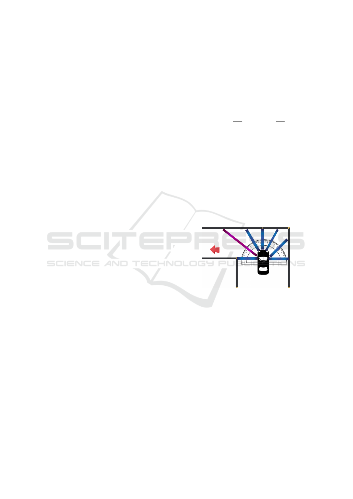
After generating the 12 lines (one for each seg-
ment), the algorithm focuses on the points in front of
the robot. At this time, he analyzes the six segments in
front of him. If the sum of the lines of the segments to
the left of the robot is greater than that to the right and
in front of the robot, it turns to the left. If the sum of
the straight lines of the segments to the right is greater,
it turns to the right. Otherwise, he keeps moving for-
ward. The lines are adjusted to double the size of the
robot to avoid obstacles and ensure smooth maneuver-
ing. Figure 3 illustrates the robot’s decision-making
process, the imaginary segments generated by LIDAR
points, and the autonomous navigation method.
Figure 3: Direction chosen by the robot.
4.3.2 Mapping and Location
Several approaches and methods have been developed
to enable mobile robots to navigate efficiently while
performing specific tasks. Among the various exist-
ing approaches, the one based on maps has proven
to be the most effective. For an Autonomous Mobile
Robot (AMR), mapping involves creating a meaning-
ful representation of the environment that serves as a
model for the robot, providing it with the knowledge
necessary to make decisions and achieve its objectives
(Alatise and Hancke, 2020). The robot’s ability to
make decisions is intrinsically linked to knowledge of
the environment, which introduces the need to solve
the problem of robot localization.
These problems are interdependent, solving one
implies solving the other, and vice versa. In this con-
text, the problem is formally approached using SLAM
ICEIS 2024 - 26th International Conference on Enterprise Information Systems
948
(Simultaneous Localization and Mapping), which in-
volves the simultaneous calculation of the different
positions of the robot and the environment model.
In the scope of this study, predefined labels spaced
throughout a maze are detected by the robot through
the camera module. These tags not only locate the
robot in the environment but also, connotatively, ”in-
form and validate to the robot that it is navigating
in an environment where its characteristics have been
detected.” In other words, the labels indicate that the
robot is currently navigating the maze. Upon detect-
ing a tag, the robot stops its movement, collects data
with the LIDAR sensor over a 5-second interval, and
then continues its trajectory avoiding obstacles. This
process is repeated when another tag is found, trigger-
ing the LIDAR again to map the area. After collect-
ing environmental information by LIDAR, the data is
stored in a text file with time stamp information. Us-
ing Python and the Matplotlib library, this data, orig-
inally represented in polar coordinates, is converted
to coordinates on a Cartesian plane. Subsequently, a
graph is generated that faithfully represents the local
mapping obtained.
4.4 Environment Preparation
In this section, we will detail the preparation of the
environment for the navigation and SLAM mapping
operations of the autonomous mobile robot. We opted
for a maze built with cardboard boxes, aiming to cre-
ate a significant challenge for the robotic system un-
der study. The choice of this maze seeks to simulate
realistic conditions, challenging the robot’s ability to
navigate a dynamic, three-dimensional environment.
The maze consists of four corridors and open ar-
eas, strategically constructed from cardboard boxes.
The arrangement of the boxes was planned to create
a challenging environment, testing the robot’s agility
and efficiency in detecting, navigating, and mapping
obstacles. For aesthetic purposes, the boxes were cov-
ered with sheets of white A4 paper.
The dimensions of the maze include two rectan-
gular walls of different sizes. The external wall mea-
sures 2.80 meters long by 2.10 meters wide, while
the internal wall is 1.50 meters long and 1.20 meters
wide. The height of the walls varies due to the pres-
ence of boxes of different sizes and arrangements, im-
itating a heterogeneous and diverse environment.
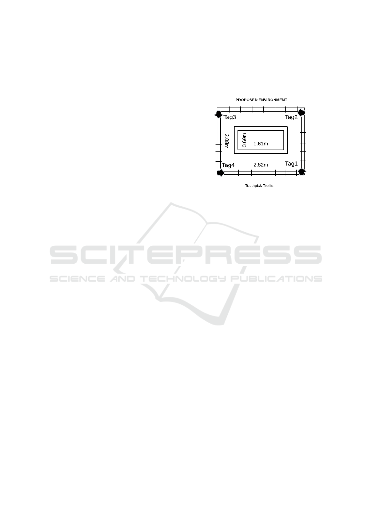
To support the walls, we used trusses made from
recyclable wooden sticks, fixed with hot glue. Fur-
thermore, along the four corridors, eight predefined
”tags” were positioned to locate the robot in the envi-
ronment. Four of them are at the ends of the maze (in
each corner), while the other four are centered on each
inner wall. This arrangement provides crucial refer-
ence points for robot navigation and mapping. Figure
4 illustrates the proposed environment for the experi-
ments in this study.
Figure 4: 2D Floor Plan of the Proposed Environment.
5 EXPERIMENTAL RESULTS
In this section, we present the results obtained during
the experiments conducted to evaluate the effective-
ness and performance of the proposed Simultaneous
Localization and Mapping (SLAM) approach based
on tag recognition using the ORB+RANSAC combi-
nation. The experiments were carried out in a real en-
vironment where the mobile robot was programmed
to operate autonomously, avoiding obstacles while in-
teracting with previously positioned tags.
5.1 Mobile Robot
The robot used in the experiments and its physical at-
tributes will be presented in this section.
5.1.1 Mechanical Characteristics - Physical
Structure
The basic structure of the robot is made of blue
acrylic, with dimensions of 5 mm thick, 18 cm long,
and 13 cm wide. Below it, there is a metal plate struc-
ture measuring 13 cm long, 8 cm wide, and extend-
ing diagonally for approximately 3 cm in two ends to
support the engines. The robot has two heels, each
connected to a motor, positioned at the top right and
bottom left sides, respectively. Additionally, on each
side (right and left), there is a slidewheel connected
to a track that passes through another wheel, con-
trolled by the corresponding motor. A frame is built
4 cm above the basic robot structure using the same
acrylic material, with dimensions 17 cm long and 11
An Extension of Orbslam for Mobile Robot Using Lidar and Monocular Camera Data for SLAM Without Odometry
949
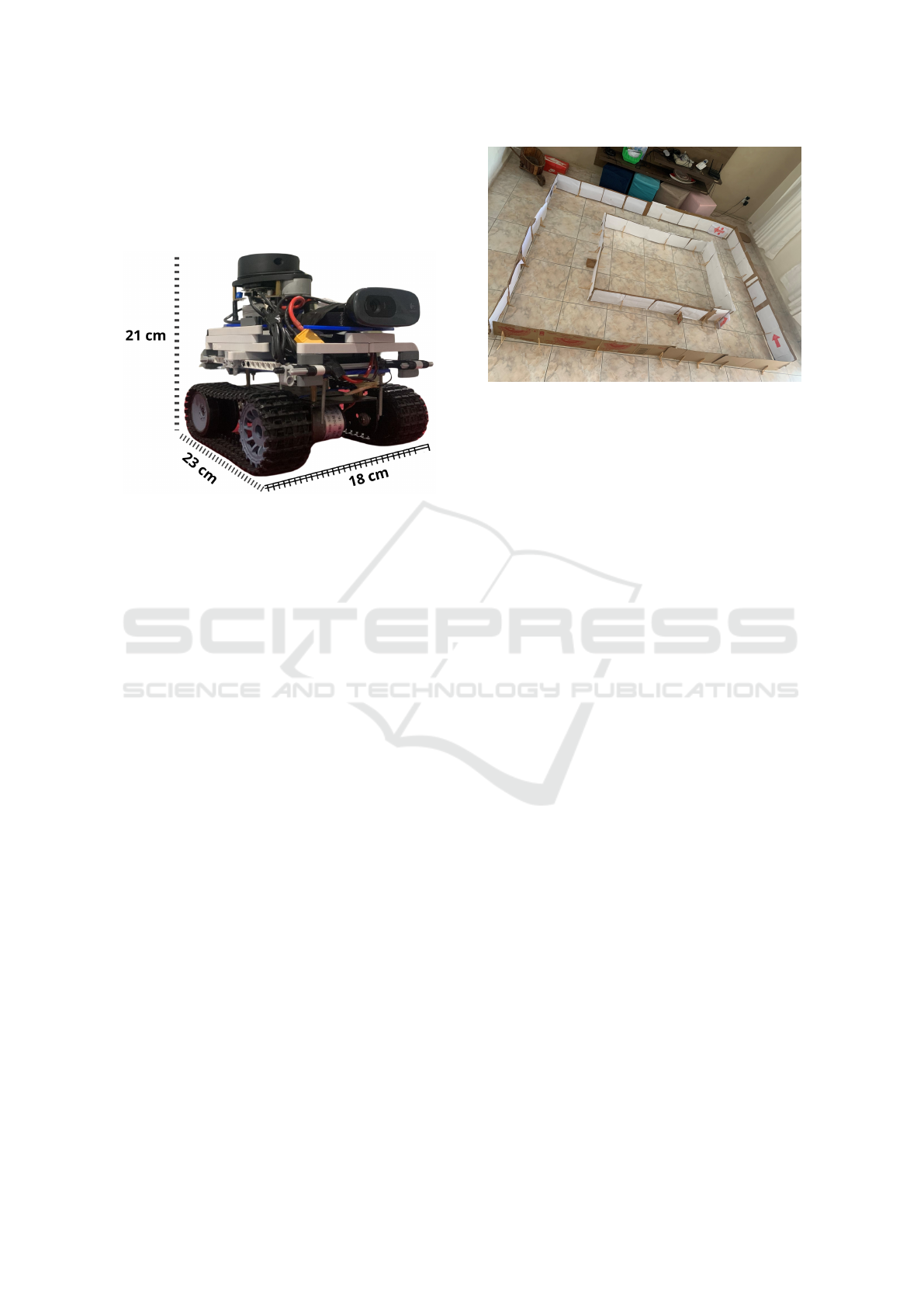
cm wide, where the robot’s visual sensors are located.
The overall dimensions of the robot are 21 cm high,
23 cm long, and 18 cm wide, respectively. The robot
can be viewed from its cavalry perspective in Figure
5.
Figure 5: Knight’s perspective of the Scramble Robot.
5.1.2 Mechanical Characteristics - Hardware
The robot developed for this work is composed of two
main hardware components to control the actuators:
An Arduino Uno and an expansion board (Shield)
from the manufacturer Pololu model MC33926. This
expansion board (Shield) is an H bridge controller
composed of two drivers that operate between an ap-
propriate voltage between 5 and 28 volts with a direct
current of around 3 Amps and is intended to control
two direct current (DC) motors.
The robot has two DC motors that operate with an
appropriate voltage between 6 and 12 volts. Each en-
gine weighs approximately 100 grams, has a 39mm
cylinder, and its maximum speed can reach 350 rpm.
One of the motors is connected to the upper right
wheel and the other to the lower left wheel.
On the basic acrylic robot structure on the first
floor, the Arduino Uno and motor driver shield are po-
sitioned at the front, while the Raspberry Pi 3 Model
B is placed at the back. At the front of the sec-
ond floor, a Logitech C270 RGB camera and a cir-
cuit board for power distribution are located, while at
the rear is positioned the RPLIDAR A1M8 Pro Li-
dar TOF 360
◦
with 8m scanning range sensor. The
camera and Lidar are integrated into the robot’s per-
ception module and are fundamental for simultaneous
robot mapping and localization (SLAM).
The Raspberry Pi is responsible for interpreting
and processing the data obtained by visual sensors po-
sitioned on the second floor of the robot. The Rasp-
berry Pi is a fully functional minicomputer powered
Figure 6: Original image captured from the Labyrinth with
Tags Positioned.
by a Broadcom BCM2837 system-on-chip (SoC),
which houses four high-performance ARM Cortex-
A53 processing cores. This device operates at a fre-
quency of 1.2 GHz and has a cache memory of 32 kB
at level 1 and 512 kB at level 2. Additionally, it in-
cludes an integrated graphics processor connected to
a 1 GB LPDDR2 memory module. With four USB
ports, a 40-pin input and output bus, Bluetooth Low
Energy (BLE), and built-in Wi-Fi, the Raspberry Pi
offers a versatile and powerful platform for a variety
of projects and applications(Balon and Simi
´
c, 2019).
5.2 Experiment Setup
The experiments were conducted with the mobile
robot autonomously navigating the proposed environ-
ment. The robot was equipped to recognize tags po-
sitioned in the environment and map the areas sur-
rounding each identified tag. At each tag detection,
four top-view images were captured, and local maps
were generated from the points collected by the lidar
sensor.
5.3 Visual Results
Figure 6 illustrates the originally captured image
of the environment showing the arrangement of the
boxes, the positioned tags, the corridor areas, and the
cardboard wall supports made from wooden sticks.
Figure 7 shows the robot’s vision at the moment
tag1 was found in the environment and the orb method
was used to find correspondence between the tags and
the robot’s momentary vision. For each tag detection,
an image of the top view of the tag was captured.
robot. The robot created an occupancy grid map to
represent the environment as it navigated and mapped
the area near the tag. Figure 8 illustrates one of these
images, highlighting the position of the robot when
ICEIS 2024 - 26th International Conference on Enterprise Information Systems
950
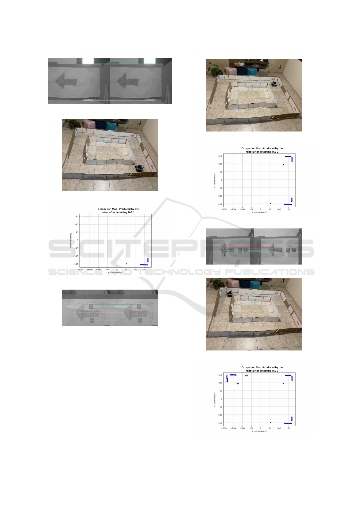
Figure 7: Robot vision when finding tag1.
Figure 8: Robot Position when Tag1 is Recognized.
Figure 9: Global Map Update - detecting Tag1.
Figure 10: Robot vision when finding tag2.
recognizing Tag1. After identifying Tag1, the robot
performed local mapping based on the view avail-
able at that time and then updated the global map, as
shown in Figure 9.
Similar steps were repeated for Tags 2, 3 and 4,
after the robot recognized the corresponding tags, as
illustrated in Figures 10 to 18. Each tag detection re-
sulted in the capture of a top view image, followed by
the generation of a local map. and updating the global
marking map. environment. These results highlight
the effectiveness of our SLAM method in creating ac-
curate maps and reliably localizing the robot in a dy-
namic environment.
Figure 11: Robot Position when Tag2 is Recognized.
Figure 12: Global Map Update - detecting Tag2.
Figure 13: Robot vision when finding tag3.
Figure 14: Robot Position when Tag3 is Recognized.
Figure 15: Global Map Update - detecting Tag3.
An Extension of Orbslam for Mobile Robot Using Lidar and Monocular Camera Data for SLAM Without Odometry
951
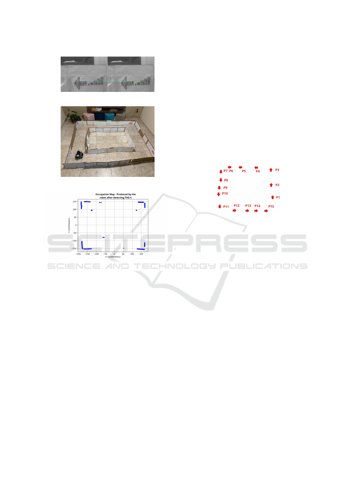
Figure 16: Robot vision when finding tag4.
Figure 17: Robot Position when Tag4 is Recognized.
Figure 18: Global Map Update - detecting Tag4.
5.4 Quantitative Results
The quantitative results of the experiments included
metrics such as the accuracy of the robot’s location
relative to reference tags, the quality of the generated
maps, and the processing time required for mapping
and localization operations.
5.5 Discussion of Results
The experimental results demonstrate the effective-
ness of the proposed SLAM technique in creating ac-
curate maps and accurately locating the robot in a real
environment using tags as reference points. The inte-
gration of LiDAR scans, camera images, and tag in-
formation allowed the creation of detailed maps and
efficient autonomous navigation of the robot.
5.6 Manual Positioning Experiment
To complement the experiments conducted with au-
tonomous navigation, we carried out an additional ex-
periment where the robot was manually positioned in
various positions in the proposed environment. In this
experiment, the robot did not perform autonomous
navigation but was placed in specific locations to eval-
uate the ability of the SLAM approach to map the en-
vironment from different points of view.
5.6.1 Experiment Setup
The robot was manually positioned in several strate-
gic locations in the proposed environment. For each
position, the robot was programmed to scan the envi-
ronment with its LiDAR sensor. From this data, local
maps corresponding to each position of the robot were
generated. Figure 19 illustrates the positions in which
the robot was positioned.
Figure 19: Robot Position.
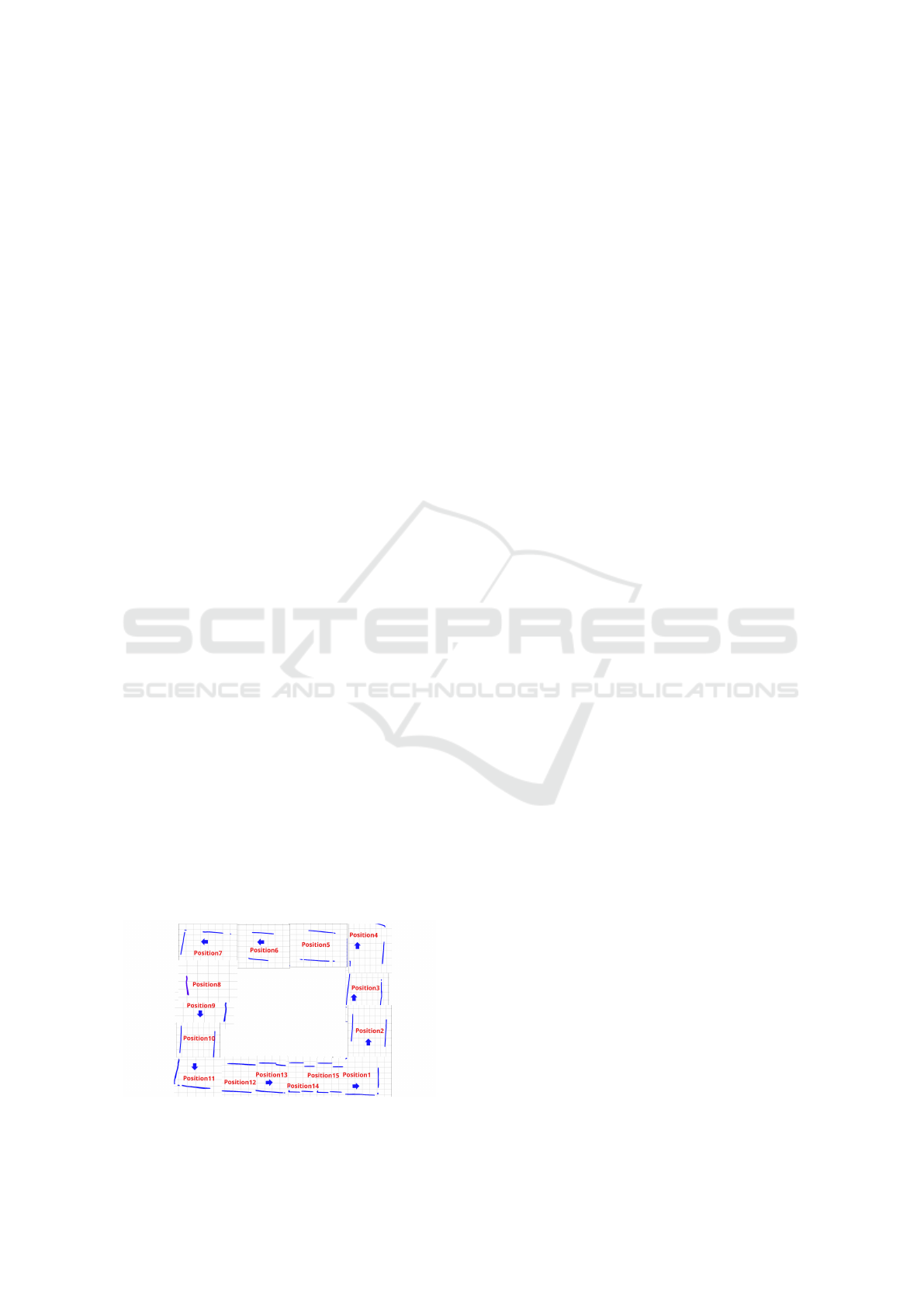
5.6.2 Results
The results of the manual positioning experiment
highlighted the effectiveness of the SLAM approach
in creating detailed maps of the environment from
different perspectives. Each positioning of the robot
was sought to generate a precise local map, high-
lighting the technique’s ability to map the environ-
ment regardless of the robot’s initial position. In Fig-
ure 20 we manually added the map corresponding to
each position in which the robot was allocated and
its corresponding map produced. However, it was
observed that the robot was unable to integrate the
maps produced, resulting in a lack of continuity be-
tween them. During the experiment, the robot had
difficulty locating in the environment due to the cre-
ation of a new reference map for each new position,
compromising its navigation and orientation capabil-
ities. The lack of visual perception through the cam-
era contributed to this limitation. Furthermore, the
processing time required for each new position of the
robot was identified as a challenge, making the pro-
cess time-consuming and increasing the likelihood of
system interruption and inoperability, especially con-
sidering the limited hardware resources available.
5.6.3 Discussion
The inclusion of the manual positioning experiment
as a control strengthens the results obtained in the au-
ICEIS 2024 - 26th International Conference on Enterprise Information Systems
952
tonomous navigation experiments. By eliminating the
autonomous navigation variable, it was possible to di-
rectly evaluate the ability of the SLAM approach to
map the environment from multiple fixed positions.
The consistent results obtained in this experiment fur-
ther corroborate the effectiveness and reliability of
the proposed SLAM technique from the first exper-
iment. However, observations made during the exper-
iment also highlight the limitations of the approach,
especially regarding map integration and continuous
robot localization. These aspects must be addressed
in our future work to ensure the improvement and ap-
plicability of the technique in dynamic and constantly
changing environments.
6 CONCLUSIONS
In conclusion, this study presents a mobile au-
tonomous robot, Scramble, equipped with an innova-
tive SLAM approach based on data fusion from an
RPLIDAR A1m8 LiDAR and an RGB camera. The
main objective was to improve the accuracy of map-
ping, trajectory planning, and obstacle detection for
autonomous mobile robots in complex and dynamic
environments through data fusion. The experimen-
tal results demonstrate the effectiveness of the pro-
posed SLAM approach. By taking advantage of vi-
sual and depth sensors, the robot successfully navi-
gated a maze-like environment, recognizing tags and
updating its global map. The fusion of visual and Li-
DAR data significantly improved the accuracy and ro-
bustness of the SLAM system, outperforming single-
sensor SLAM approaches in several scenarios.
Environmental preparation, including construc-
tion of the maze and placement of tags, aimed to
create a realistic and challenging configuration for
the robot. The experimental setup, involving au-
tonomous navigation with tag recognition, demon-
strated the robot’s ability to adapt and navigate dy-
namically, proving the effectiveness of the proposed
SLAM approach. However, the manual positioning
Figure 20: Local map and robot positions.
experiment revealed challenges related to map inte-
gration and continuous localization of the robot. Cre-
ating a new reference map for each position compro-
mised navigation capabilities, indicating the need for
improvements in map integration and localization in
dynamic environments.
The presented SLAM approach opens avenues
for future research and development. Overcoming
the identified limitations and improving the system’s
adaptability to changing environments will be cru-
cial for real-world applications of autonomous mobile
robots. The fusion of visual and LiDAR data promises
to create more accurate and robust maps, enabling
precise navigation in challenging scenarios. In sum-
mary, this research contributes to the advancement of
autonomous robot navigation by proposing and val-
idating a data fusion-based SLAM approach. As the
field continues to evolve, the findings of this study lay
the foundation for further exploration and innovation
in the domain of mobile autonomous robotics, pro-
moting the development of more reliable and efficient
systems for diverse applications.
ACKNOWLEDGEMENTS
The authors would like to thank FAPEMIG, CAPES,
CNPq, Instituto Tecnol
´
ogico Vale, and the Federal
University of Ouro Preto for supporting this work.
This work was partially funded by CAPES (Finance
Code 001) and CNPq (308219/2020-1).
REFERENCES
Al-Araji, A. S., Ahmed, A. K., and Dagher, K. E. (2019).
A cognition path planning with a nonlinear controller
design for wheeled mobile robot based on an intelli-
gent algorithm. Journal of Engineering, 25(1):64–83.
Alatise, M. B. and Hancke, G. P. (2020). A review on chal-
lenges of autonomous mobile robot and sensor fusion
methods. IEEE Access, 8:39830–39846.
Ashraf, I., Hur, S., and Park, Y. (2017). An investigation of
interpolation techniques to generate 2d intensity im-
age from lidar data. IEEE Access, PP:1–1.
Balon, B. and Simi
´
c, M. (2019). Using raspberry pi
computers in education. In 2019 42nd International
Convention on Information and Communication Tech-
nology, Electronics and Microelectronics (MIPRO),
pages 671–676. IEEE.
Barducci, A. and Scaramuzza, D. (2018). Visual odom-
etry: A survey. IEEE Transactions on Robotics,
34(6):1225–1246.
Cadena, C., Carlone, L., Carrillo, H., Latif, Y., Scaramuzza,
D., Neira, J., Reid, I., and Leonard, J. J. (2016). Past,
present, and future of simultaneous localization and
An Extension of Orbslam for Mobile Robot Using Lidar and Monocular Camera Data for SLAM Without Odometry
953

mapping: Toward the robust-perception age. IEEE
Transactions on robotics, 32(6):1309–1332.
Cantzler, H. (1981). Random sample consensus (ransac).
Institute for Perception, Action and Behaviour, Divi-
sion of Informatics, University of Edinburgh, 3.
Cao, J., Liao, X., and Hall, E. (1999). Reactive naviga-
tion for autonomous guided vehicle using neuro-fuzzy
techniques. 3837.
Cheng, J., Zhang, L., Chen, Q., Hu, X., and Cai, J. (2022).
A review of visual slam methods for autonomous driv-
ing vehicles. Engineering Applications of Artificial
Intelligence, 114:104992.
da Cruz J
´
unior, G. P. et al. (2021). Localizac¸
˜
ao e mapea-
mento para rob
ˆ
os m
´
oveis em ambientes confinados
baseado em fus
˜
ao de lidar com odometrias de rodas
e sensor inercial.
Dudek, G. and Jenkin, M. (2010). Computational principles
of mobile robotics. Cambridge university press.
Grisetti, G., Stachniss, C., and Burgard, W. (2007).
Improved techniques for grid mapping with rao-
blackwellized particle filters. IEEE transactions on
Robotics, 23(1):34–46.
Khan, S. and Ahmmed, M. K. (2016). Where am i?
autonomous navigation system of a mobile robot in
an unknown environment. 2016 5th International
Conference on Informatics, Electronics and Vision
(ICIEV), pages 56–61.
Kurt-Yavuz, Z. and Yavuz, S. (2012). A comparison of ekf,
ukf, fastslam2. 0, and ukf-based fastslam algorithms.
In 2012 IEEE 16th International Conference on In-
telligent Engineering Systems (INES), pages 37–43.
IEEE.
Li, Z., Zhao, X., and Li, Y. (2023). Dense reconstruc-
tion of substation room with lsd slam. In Third In-
ternational Conference on Artificial Intelligence, Vir-
tual Reality, and Visualization (AIVRV 2023), volume
12923, pages 193–201. SPIE.
Miranto, H. A., Jati, A. N., and Setianingsih, C. (2019). Re-
alization of point cloud maps using ros & visual sen-
sor on raspberry pi 3 based mobile robot. 2019 4th
International Conference on Information Technology,
Information Systems and Electrical Engineering (ICI-
TISEE), pages 517–522.
Mur-Artal, R., Montiel, J. M. M., and Tardos, J. D. (2015).
Orb-slam: a versatile and accurate monocular slam
system. IEEE transactions on robotics, 31(5):1147–
1163.
Mur-Artal, R. and Tard
´
os, J. D. (2016). Orb-slam2:
An open-source slam system for monocular, stereo,
and rgb-d cameras. IEEE Transactions on Robotics,
33:1255–1262.
Ni, J., Wang, X., Gong, T., and Xie, Y. (2022). An improved
adaptive orb-slam method for monocular vision robot
under dynamic environments. International Journal
of Machine Learning and Cybernetics, 13(12):3821–
3836.
Ran, T., Yuan, L., and Zhang, J. (2021). Scene perception
based visual navigation of mobile robot in indoor en-
vironment. ISA transactions, 109:389–400.
Rublee, E., Rabaud, V., Konolige, K., and Bradski, G.
(2011). Orb: An efficient alternative to sift or surf.
In 2011 International conference on computer vision,
pages 2564–2571. Ieee.
Serrata, A. A. J., Yang, S., and Li, R. (2017). An intelli-
gible implementation of fastslam2.0 on a low-power
embedded architecture. EURASIP Journal on Embed-
ded Systems, 2017:1–11.
Skoltech Robotics (2024). RPLidar Python Module Repos-
itory. https://github.com/SkoltechRobotics/rplidar.
Accessed on: 01/31/24.
Soares, J., Gattass, M., and Meggiolaro, M. (2022). Ma-
peamento e localizac¸
˜
ao simult
ˆ
aneos em ambientes
din
ˆ
amicos usando detecc¸
˜
ao de pessoas. In Anais Es-
tendidos do XIV Simp
´
osio Brasileiro de Rob
´
otica e
XIX Simp
´
osio Latino-Americano de Rob
´
otica, pages
109–120, Porto Alegre, RS, Brasil. SBC.
Son, D. T., The, A. M., Duong, T. D., Chuong, L. V.,
Cuong, T. H., and Phuong, H. S. (2021). The practice
of mapping-based navigation system for indoor robot
with rplidar and raspberry pi. 2021 International Con-
ference on System Science and Engineering (ICSSE),
pages 279–282.
Toroslu, I. and Do
˘
gan, M. (2018). Effective sensor fusion
of a mobile robot for slam implementation. 2018 4th
International Conference on Control, Automation and
Robotics (ICCAR), pages 76–81.
ˇ
Culjak, I., Abram, D., Pribani
´
c, T., D
ˇ
zapo, H., and Cifrek,
M. (2012). A brief introduction to opencv. 2012
Proceedings of the 35th International Convention
MIPRO, pages 1725–1730.
ˇ
St
ˇ
ep
´
an, P., Kral, L., Kulich, M., and Preu’il, L. (1999).
Open control architecture for mobile robot. IFAC Pro-
ceedings Volumes, 32:8434–8439.
Weiss, U. and Biber, P. (2011). Plant detection and map-
ping for agricultural robots using a 3d lidar sensor.
Robotics and autonomous systems, 59(5):265–273.
Zong, W., Chen, L., Zhang, C., Wang, Z., and Chen, Q.
(2017). Vehicle model based visual-tag monocular
orb-slam. 2017 IEEE International Conference on
Systems, Man, and Cybernetics (SMC), pages 1441–
1446.
ICEIS 2024 - 26th International Conference on Enterprise Information Systems
954
