
A Sampling-Based Approach to UAV Manipulator Path Planning
Zamoum Housseyn
1 a
, Guiatni Mohamed
2 b
, Bouzid Yasser
2 c
, Alouane Mohamed Amine
2
and
Khelal Atmane
1
1
Guidance and Navigation Laboratory, Ecole Militaire Polytechnique, Algiers, Algeria
2
Control of Complex Systems and Simulators Laboratory, Ecole Militaire Polytechnique, Algiers, Algeria
Keywords:
Path Planning, Sampling-Based Methods, Random Geometric Model, UAMs, UAV Manipulator.
Abstract:
This paper presents a new approach to path planning for unmanned aerial manipulator systems (UAMs) us-
ing Sampling-Based Methods and Random Geometric Models (RGM) to efficiently search the configuration
space for feasible, collision-free paths. The RGM generates random points in the UAM’s workspace to guide
sampling-based algorithms in constructing graphs that link the aerial manipulator’s initial and final positions.
These graphs are then explored using the RRT
∗
algorithm to find an optimal collision-free path. The effec-
tiveness of this approach is demonstrated through different scenarios, showing that it outperforms existing
path planning techniques in terms of efficiency, computing time, and robustness. The proposed framework is
adaptable to various application scenarios and environments, making it a valuable tool for applications such
as search and rescue missions, surveillance, and inspection tasks.
1 INTRODUCTION
Unmanned Aerial Vehicles (UAVs) equipped with
manipulator’s arms have become increasingly popu-
lar in recent years, offering a versatile and efficient
solution for various applications, including pick up,
place and transportation of objects, smart agriculture,
object manipulation, inspection, and construction, in
environments that are difficult or unsafe for humans
to access (Ruggiero et al., 2018).
Generating efficient, collision-free trajectories for
UAV manipulators is one of the main challenges in
their operation, as it is critical for performing complex
tasks accurately and quickly. However, path planning
for UAV manipulators is a difficult problem due to
several factors. The physical design of the aerial ma-
nipulation system may limit its range of motion due
to size constraints or design choices made during sys-
tem development. Additionally, the high degree of
freedom and complex manipulator dynamics further
complicate the path-planning process. These factors
make it challenging to develop trajectory-planning al-
gorithms that can handle the complex nature of UAV
manipulators while generating efficient, collision-free
a
https://orcid.org/0000-0002-3971-7426
b
https://orcid.org/0000-0002-5899-6862
c
https://orcid.org/0000-0002-8400-9912
paths.
Recently, there has been a growing interest in the
use of sampling-based algorithms to solve the prob-
lem of trajectory planning for aerial manipulators.
In their work, M. Brunner et al. (Brunner et al.,
2022) proposed a sampling-based approach for fully-
actuated MAVs that can exert forces and torques in six
degrees of freedom (6 DoF). This makes them well-
suited for aerial manipulation tasks that require pre-
cise control. The sampling-based approach utilized
in their work does not rely on an analytical model of
the interaction dynamics. This allows the approach
to handle multiple and recurring contacts between the
aerial manipulator and the environment. In (Yavari
et al., 2022), M. Yavari proposes an integrated plan-
ning strategy for object retrieval using a sampling-
based approach called Lazy-Steering-RRT
∗
. This ap-
proach plans the motion of an Unmanned Aerial Ma-
nipulator (UAM) from its starting point to a pre-
grasp state while minimizing the motion of the arm.
Limited-range sensors onboard facilitate on-the-fly
planning using Machine-Learning-based. The authors
in (Kim et al., 2019) propose a path planning ap-
proach for an aerial pick-and-place task, where an
aerial manipulator is required to pick up or place an
object at specified waypoints with partial state vari-
able constraints. The proposed framework is based on
the informed RRT
∗
algorithm in a bidirectional man-
80
Housseyn, Z., Mohamed, G., Yasser, B., Amine, A. and Atmane, K.
A Sampling-Based Approach to UAV Manipulator Path Planning.
DOI: 10.5220/0012761700003758
Paper published under CC license (CC BY-NC-ND 4.0)
In Proceedings of the 14th International Conference on Simulation and Modeling Methodologies, Technologies and Applications (SIMULTECH 2024), pages 80-90
ISBN: 978-989-758-708-5; ISSN: 2184-2841
Proceedings Copyright © 2024 by SCITEPRESS – Science and Technology Publications, Lda.

ner and incorporates an extra merging process to in-
tegrate the trees from the start and goal points. In
(Caballero et al., 2018), an airborne robotic system
with two arms and a lengthy bar extension is designed
for long-range manipulation in crowded settings. The
authors provide detailed information on the trajectory
planning performance of this system using a planner
based on the Rapidly-exploring Random Tree (RRT
∗
)
algorithms. In (Lee et al., 2015), the authors present
the planning of multiple aerial manipulators for coop-
erative transport. The desired path for each aerial ma-
nipulator is obtained by using RRT
∗
to transport an
object to the desired position while taking into con-
sideration the constraints of the end effector’s capture
point.
Ying Gaoyang et al. introduced an enhanced ver-
sion of the RRT algorithm called IRRT, which im-
proves the selection strategy of the root node and in-
corporates trajectory distance constraints to enhance
the quality of the planned trajectory (YIN et al.,
2017). However, this algorithm still faces challenges
related to high path cost and slow convergence speed.
To address these issues, Jiaming Fan et al. incorpo-
rated a goal biasing strategy and a dichotomy-based
approach to create a more goal-oriented sampling
method in the RRT
∗
algorithm, resulting in the PF-
RRT
∗
algorithm. This modification improves plan-
ning efficiency and search speed (Fan et al., 2022).
Another approach proposed by Huang J et al. is the
Bi-directional-Rapidly Exploring Random Tree (Bi-
RRT
∗
) algorithm, which avoids invalid expansion,
reduces storage requirements, and enhances conver-
gence speed (Huang and Sun, 2020). However, it
may encounter difficulties in extremely complex en-
vironments. In conclusion, while the RRT algorithm
is a widely used path planning algorithm, adjustments
and optimizations are still necessary to improve its ef-
ficiency and effectiveness in various scene environ-
ments with different complexities.
Despite their effectiveness, conventional
sampling-based techniques for aerial manipula-
tor systems have limitations. These techniques do
not incorporate the geometric model of the robot
because they are designed to operate in a probabilistic
framework.
This paper proposes a new path-planning method
for UAMs that utilizes sampling-based algorithms
and the direct geometric model (DGM) and inverse
geometric model (IGM) equations to describe the
coupled motions between the UAV and its manipu-
lator’s arm. The proposed approach combines the
strengths of sampling-based methods and the RGM,
which can be used together with DGM and IGM to
generate efficiently achievable paths that can navi-
gate complex and cluttered environments. Further-
more, this algorithm can efficiently explore high-
dimensional spaces and find optimal solutions in
terms of computation time and robustness compared
to conventional methods in the literature.
The rest of the document is organized as follows:
Section 2 presents the mathematical formulation of
the path planning problem and the direct and inverse
geometric modelling of UAMs. In Section 3, the pro-
posed path planning strategy and the details of the al-
gorithm developed in this work are described. Section
4 presents the different results obtained from imple-
menting the algorithm for several scenarios. Finally,
Section 5 concludes with the results and recommen-
dations for future research.
2 MATHEMATICAL
FORMULATIONS OF THE
PROBLEM
Path planning for a UAV with a manipulator’s arm in-
volves finding a collision-free path that the system can
follow from an initial position to a desired goal posi-
tion. The mathematical formulation of this problem
can vary depending on the specific scenario and ob-
jectives, but here are some of the common mathemat-
ical formulations used in path planning:
• Let X ⊆ R
3
is the state space of the planning prob-
lem.
• The states that collide with the obstacles are called
X
obs
⊂ X, and X
dead
⊂ X is the dead space or ”un-
reachable space”, the states in which an aerial ma-
nipulator cannot manipulate an object where it is
unable to reach it due to limitations in its physical
structure or the constraints of the task.
• Let X
free
= X\X
obs
∩X \X
dead
is the set of admissi-
ble states that results for the aerial robot, the initial
state is X
start
, and the desired finale state is X
goal
.
Definition 1. A feasible path is defined for an aerial
manipulator system, if it is a collision-free path and
if there is a sequence of states σ = [σ
B
, σ
e
] defined as
follows:
σ : [0, 1] × [0, 1] −→ X
free
× X
free
λ −→ σ(λ) = [σ
B
, σ
e
]
(1)
with σ(0, 0) = [X
B,start
, X
e,start
] and σ(1, 1) =
[X
final
, X
goal
].
The search for the optimal path σ
∗
e
and σ
∗
B
, which
minimizes a specified cost function, c : Γ −→ R
+
,
which connects X
start
to X
goal
through the free space
A Sampling-Based Approach to UAV Manipulator Path Planning
81
X
free
is the formal definition of the optimal planning
problem and is expressed as follows:
σ
∗
B
= argmin
σ
B
∈Γ
{c(σ
B
) | ∀s ∈ [0, 1], σ
B
(t) ∈ X
free
} (2)
Sampling-based methods such as RRT and RRT
∗
are helpful for generating feasible paths that satisfy
constraints such as obstacle avoidance. However,
sampling-based methods cannot consider the UAV’s
positioning model or unreachable positions, as shown
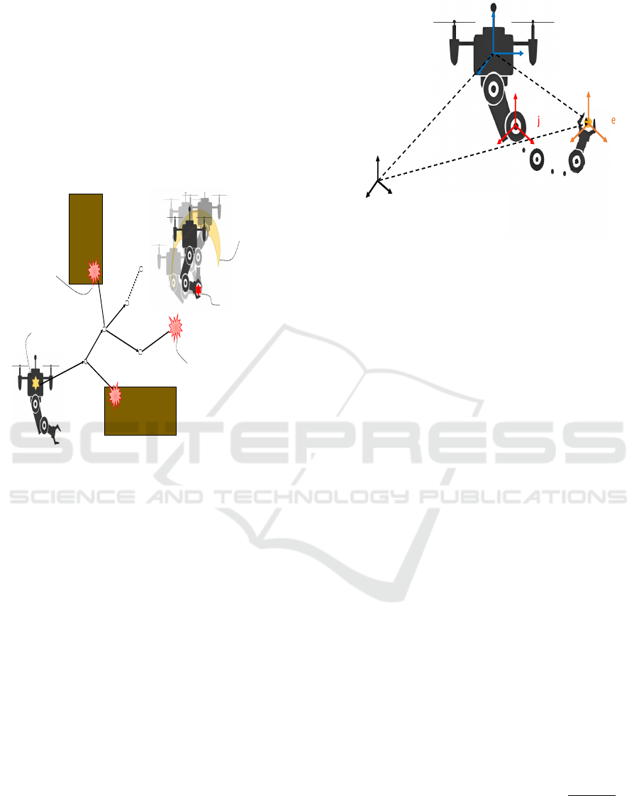
in Fig.1.
Xstart
Xrand
Xnew
Xnear
Xgoal
Collision with an
obstacle
All possible positions
for the UAV to reach
its target
A position where the UAV cannot
reach the target "dead zone".
Figure 1: The challenges of path planning through the sam-
pling approaches of an aerial manipulator.
We consider a UAM which is a combined sys-
tem of a UAV and an n-DoF robotic arm. The
earth fixed frame {I } = (O
I
, X
I
,Y
I
, Z
I
), the body fixe
frame {B} = (O
B
, X
B
,Y
B
, Z
B
) attached to the centre
of mass of UAV, and the {B
j
} = (O
j
, X
j
,Y
j
, Z
j
) ref-
erence frame. attached to the link j of the arm are
defined in Fig. 2.
The position of {B} attached to the centre of UAV
with respect to {I } is given by the vector X
B
=
I
P
B
=
[xyz]
T
and X
e
=
I
P
e
= [x
e
y
e
z
e
]
T
is the position of the
end effector relative to the reference frame {B}. The
system state can be decomposed into two vectors:
The first vector χ =
X
T
e
Φ
T
e
T
, where Φ
e
=
[φ
e
θ
e
ψ
e
]
T
expressed as the generalized coordinates
of the terminal organ attached to the frame {B
e
}.
The second vector represented by the collec-
tion of state variables of the UAV and the arm
joint as ξ =
X
T
B
Φ
T
B
Q
T
a
T
, with Φ
B
=
φ θ ψ
T
gives the orientation of the UAV
with respect to the fixed reference frame {I }, Q
a
=
q
1
q
2
. . . q
n
T
represent the joint vector of
the n-DoF manipulator’s arm expressed in the refer-
ence frame {B}.
{I}
{B}
{B }
{B }
I
P
B
I
P
e
B
P
e
Figure 2: Configuration space of an unmanned aerial ma-
nipulator (i.e. a UAV with a robot arm with n-DoF) in our
proposed configurations.
2.1 Direct Geometrical Models
The direct geometrical problem consists in determin-
ing the operational coordinates
I
P
e
of the end effector,
according to the movements of the UAV as well as the
movement of the manipulator’s joints.
Definition 2. Consider D
G
as a mathematical func-
tion describing the transition from the operational co-
ordinate space N ⊆ R
6
to the joint space M ⊆ R
6+n
as follows:
D
G
: N −→ M
ξ −→ χ = D
G
(ξ)
(3)
The DGM problem is solved geometrically using
the following system of equations:
I
P
e
=
I
P
B
+
I
R
B
(Φ
B
) ∗
B
P
e
(Q
a
)
I
R
e
(Φ
e
) =
I
R
B
(Φ
B
) ∗
B
R
e
(Q
a
) = R (Φ
B
, Q
a
)
(4)
where represent where
b
R
a
is the rotation matrix from
frame {a} to frame {b}.
Based on the system of equations 4 the function
D
G
can be given as follows:
D
G
=
"
D
+
G
D
−
G
#
=
X
e
Φ
e
=
X
B
+ G(Φ
B
, Q
a
)
H (Φ
B
, Q
a
)
.
(5)
with the function G(Φ
B
, Q
a
) =
I
R
B
(Φ
B
) ∗
B
P
e
(Q
a
)
and the function H (Φ
B
, Q
a
) is defined as:
H (Φ
B
, Q
a
) =
atan2(R (Φ
B
, Q
a
)
32
, R (Φ
B
, Q
a
)
33
)
atan2
−R (Φ
B
, Q
a
)
31
,
q
R
2
32
+ R
2
33
atan2(R (Φ
B
, Q
a
)
21
, R (Φ
B
, Q
a
)
11
)
(6)
where R (Φ
B
, Q
a
)
i j
represents the elements of the ma-
trix R (Φ
B
, Q
a
).
SIMULTECH 2024 - 14th International Conference on Simulation and Modeling Methodologies, Technologies and Applications
82

To go further, the equation (5) shows all the suit-
able positions of the drone to reach its target with its
end effector for different values of Φ
B
and Q
a
. This
result is then used in the trajectory planning to guide
the UAV to the appropriate region all based on the
D
+
G
-function.
2.2 Inverse Geometrical Models
The inverse geometric approach is fundamental to the
control of the UAM as it allows the calculation of the
UAV motions and the manipulator arm joint variables
required to move the end effector to a desired posi-
tion.
Definition 3. Consider I
G
as a mathematical function
describing the transition from the joint space M to the
operational coordinate space N as follows:
I
G
: M −→ N
χ −→ ξ = I
G
(χ)
(7)
The inverse geometry issue entails calculating the
X motions of the UAV as well as the joints of the ma-
nipulator Q
a
. However, let’s consider equation (5).
We have a system of non-linear equations of several
variables from R
6
→ R
6+n
. The inverse analytical
resolution of this system is quite complex due to sev-
eral factors: the problem to be solved is a system of
generally nonlinear equations, several solutions can
be found, and no solutions can be found after an ana-
lytical mathematical calculation.
The General Paul Inversion method is a mathe-
matical approach used to solve the inverse geometric
problem for robotic manipulators. This approach used
homogeneous transformation matrices
j
T
i
to achieve
the desired position and orientation of the end effector
given by the matrix U(
I
R
e
(Φ
e
d
),
I
P
e
d
) as follows:
U(
I
R
e
(Φ
e
d
),
I
P
e
d
) =
I
R
e
(Φ
e
d
)
I
P
e
d
0
1×3
1
(8)
The passage from the frame of reference attached
to the end organ {B
e
} to the inertial frame {I }, is
provided by the matrix:
U =
I
T
e
=
I
T
B
B
T
1
1
T
2
2
T
3
. . .
n
T
e
(9)
we use this equation (9) to compute the manipulator
arm state variables Q
a
using the following recursive
method:
U =
I
T
B
B
T
1
1
T
2
2
T
3
. . .
n
T
e
B
T
I
U =
B
T
1
1
T
2
2
T
3
. . .
n
T
e
1
T
B
B
T
I
U =
1
T
2
2
T
3
. . .
n
T
e
2
T
1
1
T
B
B
T
I
U =
2
T
3
. . .
n
T
e
.
.
.
n
T
n−1
. . .
2
T
1
1
T
B
B
T
I
U =
n
T
e
−→ Q
a
(10)
With the assumption of hovering manipulation
(φ = θ = 0) we can easily deduce the vector Q
a
=
L(X
e
, Φ
e
) replacing Φ
e
d
with Φ
e
, and X
e
with X
e
d
.
Then to determine the position of the UAV presented
by the vector X
B
we use the function D
+
G
developed
in equation (5), hence the position expression of the
UAV is X
B
= X
e
− G(Φ
B
, Q
a
).
Finally, the function I
G
described the IGM can be
given as follows:
I
G
=
I
+
G
Φ
B
I
−
G
=
X
B
Φ
0
B
Q
a
=
X
e
− G(Φ
0
B
, Q
a
)
Φ
B
(0, 0, ψ
d
)
L(X
e
, Φ
e
)
(11)
One advantage of the Inversion method is that it
provides a mathematical solution to the inverse ge-
ometric problem for UAV manipulators. However,
this method may disregard constraints such as obsta-
cle avoidance.
3 PATH PLANNING STRATEGY
Path planning is a critical component of the con-
trol system used in aerial manipulation. It involves
the creation of a path through obstacle avoidance,
which an autonomous vehicle should follow to reach
a particular destination. Its benefits include increased
safety, efficiency and autonomy. These advantages
help to reduce operational costs and ensure the effi-
cient use of UAM.
Sampling-based planners’ algorithms have
demonstrated high potential in finding fast solutions
for high-dimensional robots. Furthermore, some of
these methods bring the possibility of generating
motion plans that optimize certain cost functions
and use heuristics guide, as for the Informed RRT
∗
(Gammell et al., 2014). The algorithm is an extension
of the RRT algorithm, which uses heuristics to guide
the exploration of the RRT tree to the goal location
using information about the distance to the goal and
the quality of the paths that have been explored so
far. These techniques allow Informed RRT* to find
an optimal path to the goal in a more efficient manner
than the original RRT algorithm.
In this work, trajectory planning for a manipula-
tor UAV using sampling and random geometric model
(RGM) based methods is a technique used to gener-
ate feasible trajectories for an unmanned aerial vehi-
cle (UAV) with a manipulator’s arm.
This technique is divided into two steps, in the first
step the sampling is based on RRT* to ensure optimal
search in the working space where the target object is
located while avoiding obstacles. In the second stage,
A Sampling-Based Approach to UAV Manipulator Path Planning
83

V ← {X
B,star
, X
e,star
};E ← {
/
0};
T ← {V , E};
for k = 1 to N do
X
B,RGM
← RGM(X
goal
);
X
B,nearest
← Nearest(T , X
rand
);
X
B,new
← Steer(X
B,nearest
, X
B,rand
);
if CollisionFree(X
B,nearest
, X
B,new
, map)
then
X
B,near
← Near(T , X
B,new
, r
RRT
∗
);
T ← Add(X
B,nearest
, X
B,near
, X
B,new
);
T ← Rewire(X
B,near
, X
B,new
);
else
X
B,rand
← Random(map);
X
B,nearest
← Nearest(T , X
rand
);
X
B,new
← Steer(X
B,nearest
, X
B,rand
);
if
CollisionFree(X
B,nearest
, X
B,new
, map)
then
X
B,near
← Near(T , X
B,new
, r
RRT
∗
);
T ←
Add(X
B,nearest
, X
B,near
, X
B,new
);
T ← Rewire(X
B,near
, X
B,new
);
end
end
end
T
∗
B
, T
∗
e
← DualPath(T , X
goal
, Φ
e,goal
);
return T
∗
B
, T
∗
e
;
Algorithm 1: S-RGM
∗
(X
B,start
, X
e,start
, X
goal
, map).
the sampling introduces the RGM which provides in-
formation on the system geometry to guide the sam-
pling to converge quickly to the position where the
UAM is able to position its body and manipulate it
with its arm to reach the target objects while ensuring
a safe transition between the DGM and the IGM using
the functions D
g
and I
g
developed in section 2.
The proposed planning strategy is divided into two
phases, as shown in Fig. 7. In the first phase, the
search extends to the target object around the end
point using RGM, as shown in Fig. 3 and 4. Once the
target object is found, the algorithm proceeds to the
final phase, which involves finding all possible posi-
tions of the UAM to pick up the object. All desired
paths are clearly shown in Fig. 5 and 6. The Algo-
rithm 1 presents the pseudocode for the suggested al-
gorithm using the RGM.
In order to apply this general structure to the UAV
manipulator system, some of the intermediate func-
tionalities have been adapted to the studied problem.
These particular developments will be discussed be-
low.
3.1 The RGM Function
This function generates a random sample in the con-
figuration space around the target object, using the
IGM and a random value of Φ
0
B
, Q
a
, all based on
equations (12).
X
B,RGM
= I
+
G
(X
goal
) = X
goal
− G(Φ
0
B,rand
, Q
a,rand
)
(12)
As shown in equation (11), the RGM uses random
values of the articulation variables Q
a
and the attitude
of the UAM Φ
0
B
to obtain all the possible positions
of the drone so that it can be manipulated with its
arm correctly (Fig.4 show the cloud of points gen-
erated by the RGM for two types of UAM, H -RRR
in (Zamoum et al., 2023) and Q -PRR in (Bouzgou,
2021)).
The RGM in Algorithm 2 is a compact represen-
tation of the workspace of a UAM that can be used
for efficient sampling for the manipulator arm that is
likely to lead to a successful trajectory to the target.
Φ
0
B,rand
← rand(Φ
0
Min
, Φ
0
Max
);
Q
a,rand
← rand(Q
a,Min
, Q
a,Max
);
X
B,RGM
← I
+
G
(X
goal
, Φ
0
B,rand
, Q
a,rand
);
return X
B,rand
;
Algorithm 2: RGM(X
goal
).
3.2 Nearest Neighbor Function
This function finds the nearest node in the tree T to
a given configuration X
B,RGM
or X
B,rand
. It calculates
the distance between each node in T and X
B,rand
and
returns the node with the smallest distance X
B,nearest
.
3.3 The Steer Function
This function generates a new configuration X
B,new
by
steering from the nearest node X
B,nearest
to configura-
tion X
B,rand
towards a randomly generated configura-
tion rand. The new configuration X
B,new
is generated
by taking a small step in the direction of X
B,rand
while
ensuring that the aerial manipulator remains collision-
free.
3.4 Chek Collision with Obstacle
This function checks whether the path from the near-
est node X
B,nearest
to configuration X
B,rand
to the new
configuration X
B,new
is collision-free. It does this by
checking for collisions between the aerial manipula-
tor and obstacles in the environment represented by
the map.
SIMULTECH 2024 - 14th International Conference on Simulation and Modeling Methodologies, Technologies and Applications
84
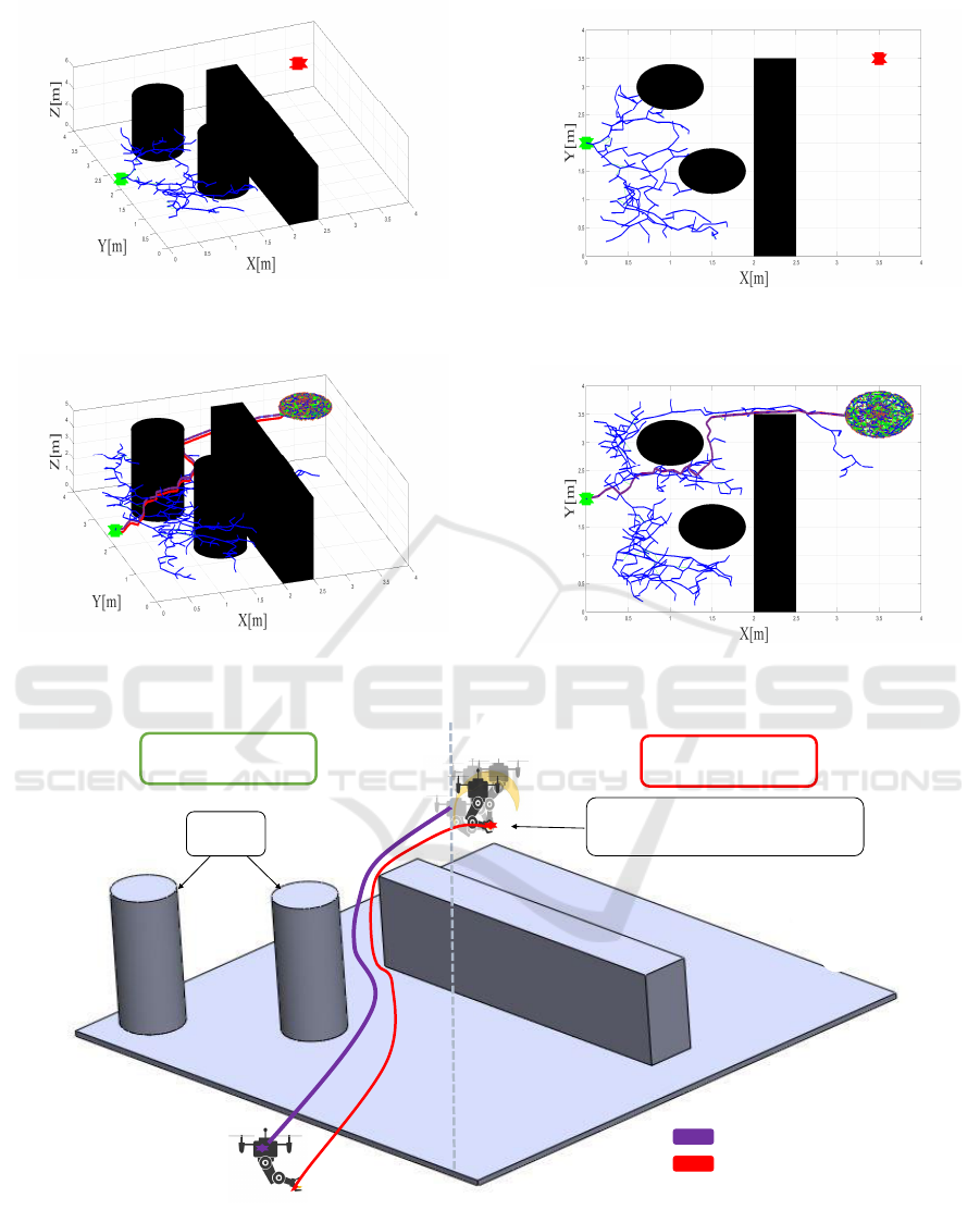
Figure 3: During each iteration in the first phase, the search
extends to the target object around the goal point using
RGM.
Figure 4: 2D representation of the first phase of the search
for the target object.
Figure 5: When the target object is found, the algorithm
ends with the final phase to find all possible positions of the
UAM to pick up the object.
Figure 6: 2D representation of the final phase to pick up the
object.
First phase
Final phase
Obstacle
UAV positioning using the RGM to
pick up the target object
Start position
UAV’s trajectory
End-effector trajectory
Figure 7: The path planning phases of the aerial manipulator that must pass to pick up the object. The start and end positions
of the UAM are shown in a green and red star. Each purple and red line shows the trajectory of the aerial manipulator’s body
and effector position, respectively.
A Sampling-Based Approach to UAV Manipulator Path Planning
85
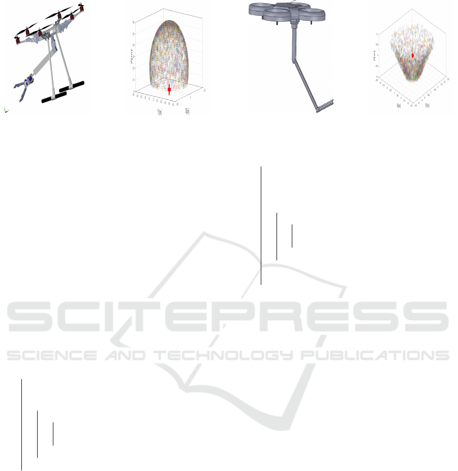
Figure 8: RGM cloud points for two types of UAM, H -RRR and Q -PRR.
3.5 The near Vertices Function
This function finds all nodes in the tree T within a
certain radius r of a given configuration X. It calcu-
lates the distance between each node in T and X and
returns the nodes with distances less than r.
3.6 Add Function
This function adds a new configuration X
B,new
to
the tree T by connecting it to its nearest neighbour
X
B,nearest
via a nearby node X
B,near
. It creates a new
edge in the tree between X
B,near
and X
B,new
through
X
B,near
.
V ← V ∪ {X
B,new
};
x
min
← X
B,nearest
;
c
min
← Cost(X
min
) + c(Line(x
min
, X
B,new
);
for ∀x
near
∈ X
B,near
do
c
new
←
Cost(x
near
) + c(Line(x
near
, X
B,new
));
if c
new
< c
min
then
if CollisionFree(x
near
, X
B,new
) then
x
min
← x
near
;
c
min
← c
new
;
end
end
end
E ← E ∪(x
min
;X
B,new
);
T ← {V , E};
return T ;
Algorithm 3: Add(X
B,nearest
, X
B,near
, X
B,new
).
3.7 Rewire Function
This function rewires the tree T to ensure optimality.
It checks if any nodes in the tree within a certain ra-
dius of X
B,new
can be reached with a shorter path via
X
B,new
. If so, it re-parents these nodes to X
B,new
and
updates the cost of the path to each of these nodes.
for ∀x
near
∈ X
B,near
do
c
near
← Cost(x
near
);
c
new
←
Cost(X
B,new
) + c(Line(X
B,new
, x
near
));
if c
new
< c
near
then
if CollisionFree(X
B,new
, x
near
) then
x
parent
← Parent(x
near
);
c
min
← c
new
;
end
end
E ← (E\{x
parent
, x
near
}) ∪ (X
B,new
, x
near
);
end
T ← {V , E};
return T ;
Algorithm 4: Rewire(X
B,near
, X
B,new
).
3.8 DualPath Function
This function finds the optimal paths from the
start configuration X
B,start
to the final configuration
X
B,Final
, and from the configuration X
e,start
to the goal
configuration X
goal
with the desired end effector ori-
entation Φ
e,goal
. It uses a bidirectional search algo-
rithm to simultaneously search for a path from the
start and end configurations and then merges the two
paths T
∗
B
and T
∗
e
to find the optimal solution.
T
∗
B
← GetsPath
B
(T );
X
B,Final
← Gets(T
∗
B
);
Q
a,Final
← I
−
G
(X
goal
, Φ
e,goal
);
X
e,Final
← D
+
G
(X
B,Final
, Φ
0
B
, Q
a,Final
);
V ← V ∪ {X
B,Final
, X
e,Final
};
T ← {V , E};
T
∗
e
← GetsPath
e
(T , X
e,Final
);
return T
∗
B
, T
∗
e
;
Algorithm 5: DualPath(T , X
goal
, Φ
e,goal
).
In summary, this algorithm uses sampling-based
methods to explore the configuration space of a UAV
SIMULTECH 2024 - 14th International Conference on Simulation and Modeling Methodologies, Technologies and Applications
86
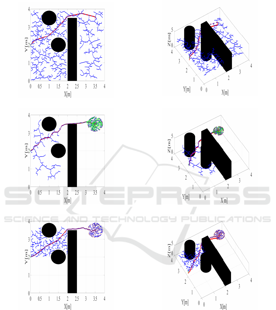
(a) RRT
∗
- 2D.
(b) RRT
∗
-3D.
(c) RRT
∗
-RGM
∗
- 2D. (d) RRT
∗
-RGM
∗
- 3D.
(e) S-RGM
∗
- 2D. (f) S-RGM
∗
- 3D.
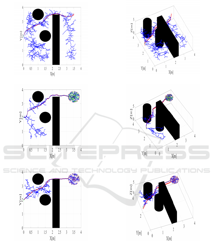
Figure 9: The first case of path planning in the second scenario to pick up the object. Each purple and red line shows the
trajectory of the aerial manipulator’s body and effector position, respectively.
manipulator and plan a collision-free trajectory. The
RGM is used to generate random samples, and the
algorithm builds a tree of nodes to represent the ex-
plored configurations. The results of the S-RGM
∗
al-
gorithm are presented in the following section.
4 SIMULATION RESULTS AND
DISCUSSION
To evaluate the efficacy of the proposed S-RGM
∗
al-
gorithm in path planning, we employed MATLAB as
A Sampling-Based Approach to UAV Manipulator Path Planning
87
(a) RRT
∗
- 2D.
(b) RRT
∗
- 3D.
(c) RRT
∗
-RGM
∗
- 2D. (d) RRT
∗
-RGM
∗
- 3D.
(e) S-RGM
∗
- 2D. (f) S-RGM
∗
- 3D.
Figure 10: The second case of path planning in the second scenario to pick up the object. Each purple and red line shows the
trajectory of the aerial manipulator’s body and effector position, respectively.
the simulation platform for this study. The simulation
experiments were conducted in a three-dimensional
environment. In two scenario, we examined a two-
dimensional environment with obstacles and com-
pared the path planning results of UAM using the
RRT
∗
and S-RGM
∗
algorithms, analyzing search time
and path length under identical conditions for a sys-
tem (H -RRR ) under identical conditions.
The Two Scenarios
In this scenarios, the algorithm is deployed within
an environment where obstacles impede the trajec-
tory towards the desired object. To replicate this sce-
SIMULTECH 2024 - 14th International Conference on Simulation and Modeling Methodologies, Technologies and Applications
88
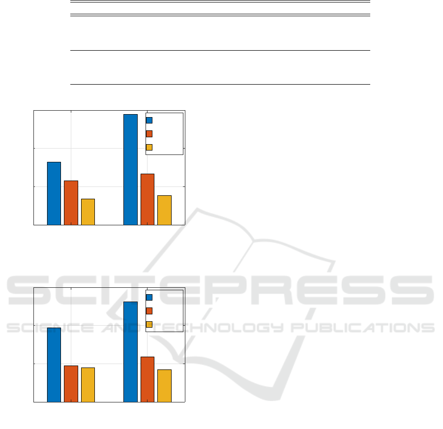
Table 1: Comparison performance table of three approaches RRT
∗
, RRT
∗
-RGM
∗
, and S-RGM
∗
in the second scenario.
Scenario Approach Time[S] Iteration Path length[UAV](m)
RRT
∗
82.2411 972 4.5432
1 RRT
∗
-RGM
∗
57.7834 547 4.2019
S-RGM
∗
34.2245 475 4.0003
RRT
∗
144.5742 1312 5.7248
2 RRT
∗
-RGM
∗
66.4797 626 4.5432
S-RGM
∗
38.3879 594 4.3307
1 2
Scenario
0
50
100
150
Sampling time[s]
RRT
*
RRT
*
-RGM
*
S-RGM
*
Figure 11: Comparison results of sampling time.
1 2
Scenario
0
500
1000
1500
Sampling Number
RRT
*
RRT
*
-RGM
*
S-RGM
*
Figure 12: Comparison results of number of samples.
nario, three obstacles are introduced into the three-
dimensional (3D) environment, as depicted in Fig.7.
Within this scenario, two distinct cases are distin-
guished for the Unmanned Aerial Vehicle (UAM) to
attain its target:
1. In the first case, the UAM executes a vertical ma-
neuver (vertical takeoff) until it reaches the alti-
tude of the desired object. Subsequently, the al-
gorithm searches for the optimal path while main-
taining a constant altitude. The algorithm under-
goes 1500 iterations, and the resulting trees gen-
erated by the algorithm are illustrated in Figure
18.
2. In the second case, the algorithm directly pursues
the optimal path, considering not only the hori-
zontal coordinates (X and Y) but also the vertical
dimension (Z). The algorithm operates for 2000
iterations, and the corresponding trees produced
by the algorithm are depicted in Figure 19.
By differentiating between these cases, the algo-
rithm aims to ascertain the most efficient path for the
UAM, taking into account both the horizontal and ver-
tical aspects of the environment.
Table 1 provides a comprehensive analysis of
the performance of three distinct approaches: RRT
∗
,
RRT
∗
-RGM
∗
, and S-RGM
∗
, within the context of the
second scenario. The table showcases key metrics,
including the sampling time, sampling number, and
path lengths for both the UAV and the manipulator
arm.
In the first case, the RRT
∗
approach exhibited
a sampling time of 82.24 seconds, using a total of
972 samples. It resulted in a UAV path length of
4.543 meters and an ARM path length of 4.94 me-
ters. Conversely, the RRT
∗
-RGM
∗
approach achieved
a slightly reduced sampling time of 57.78 seconds
with 547 samples, producing a UAV path length of
4.20 meters and an ARM path length of 4.93 meters.
Lastly, the S-RGM
∗
approach showcased superior ef-
ficiency, utilizing a sampling time of 34.22 seconds
with 475 samples, leading to a UAV path length of
4.00 meters and an ARM path length of 4.80 meters.
For scenario 2, the RRT
∗
approach recorded a
higher sampling time of 144.57 seconds, employing
1312 samples. This resulted in a UAV path length of
5.72 meters and an ARM path length of 6.12 meters.
Conversely, the RRT
∗
-RGM
∗
approach demonstrated
increased efficiency with a reduced sampling
time of 66.47 seconds and 626 samples. The
resulting UAV path length was 4.54 meters, while
the ARM path length measured 4.94 meters. Simi-
larly, the S-RGM
∗
approach showcased notable effi-
ciency with a sampling time of 38.38 seconds, uti-
lizing 594 samples, resulting in a UAV path length
of 4.3307634876 meters and an ARM path length of
5.08 meters.
In summary, the S-RGM
∗
approach exhibited su-
A Sampling-Based Approach to UAV Manipulator Path Planning
89

perior performance across both scenarios, achieving
shorter path lengths for both the UAV and the ARM.
The RRT
∗
-RGM
∗
approach demonstrated improved
efficiency in terms of sampling time (as showen
in Fig.11) and sampling number (given in Fig.12).
Meanwhile, the RRT
∗
approach showcased higher
path lengths for both the UAV and the ARM in sce-
nario 2.
5 CONCLUSIONS
The article discusses the potential advantages of aerial
robot manipulators, including their ability to manipu-
late objects in inaccessible, dangerous, or complex lo-
cations. The article proposes a solution for path plan-
ning using Sampling-Based Methods and the RGM.
The results obtained through simulation have been
satisfactory. The proposed solution provides a simple
and effective way to plan trajectories for aerial robot
manipulators, which could have significant practical
applications in the future.
REFERENCES
Bouzgou, K. (2021). Contribution
`
a l’architecture, la
mod
´
elisation et la commande d’un bras manipulateur
a
´
erien. PhD thesis, Universit
´
e Paris-Saclay.
Brunner, M., Rizzi, G., Studiger, M., Siegwart, R., and
Tognon, M. (2022). A planning-and-control frame-
work for aerial manipulation of articulated objects.
IEEE Robotics and Automation Letters, 7(4):10689–
10696.
Caballero, A., Suarez, A., Real, F., Vega, V. M., Bejar, M.,
Rodriguez-Casta
˜
no, A., and Ollero, A. (2018). First
experimental results on motion planning for trans-
portation in aerial long-reach manipulators with two
arms. In 2018 IEEE/RSJ International Conference on
Intelligent Robots and Systems (IROS), pages 8471–
8477. IEEE.
Fan, J., Chen, X., Wang, Y., and Chen, X. (2022).
Uav trajectory planning in cluttered environments
based on pf-rrt* algorithm with goal-biased strategy.
Engineering Applications of Artificial Intelligence,
114:105182.
Gammell, J. D., Srinivasa, S. S., and Barfoot, T. D. (2014).
Informed rrt: Optimal sampling-based path planning
focused via direct sampling of an admissible ellip-
soidal heuristic. In 2014 IEEE/RSJ International
Conference on Intelligent Robots and Systems, pages
2997–3004. IEEE.
Huang, J. and Sun, W. (2020). A method of feasible
trajectory planning for uav formation based on bi-
directional fast search tree. Optik, 221:165213.
Kim, H., Seo, H., Kim, J., and Kim, H. J. (2019). Sampling-
based motion planning for aerial pick-and-place. In
2019 IEEE/RSJ International Conference on Intelli-
gent Robots and Systems (IROS), pages 7402–7408.
IEEE.
Lee, H., Kim, H., and Kim, H. J. (2015). Path planning and
control of multiple aerial manipulators for a cooper-
ative transportation. In 2015 IEEE/RSJ International
Conference on Intelligent Robots and Systems (IROS),
pages 2386–2391. IEEE.
Ruggiero, F., Lippiello, V., and Ollero, A. (2018). Aerial
manipulation: A literature review. IEEE Robotics and
Automation Letters, 3(3):1957–1964.
Yavari, M., Gupta, K., and Mehrandezh, M. (2022). In-
terleaved predictive control and planning for an un-
manned aerial manipulator with on-the-fly rapid re-
planning in unknown environments. IEEE Transac-
tions on Automation Science and Engineering, pages
1–16.
YIN, G.-y., ZHOU, S.-l., and WU, Q.-p. (2017). An im-
proved rrt algorithm for uav path planning. ACTA
ELECTONICA SINICA, 45(7):1764.
Zamoum, H., Bouzid, Y., and Guiatni, M. (2023). Robust
control and recursive modelling approach for hexaro-
tor manipulator. Proceedings of the Institution of Me-
chanical Engineers, Part I: Journal of Systems and
Control Engineering, page 09596518231156814.
SIMULTECH 2024 - 14th International Conference on Simulation and Modeling Methodologies, Technologies and Applications
90
