
Performance Improvement of a Vertical Turbine Pump Accounting
for the Solid-Water Two-Phase Flow Conditions
Thomas Alphonse Mbock Singock and Guyh Dituba Ngoma
University of Quebec in Abitibi-Témiscamingue, School of Engineering,
445, Boulevard de l’Université, Rouyn-Noranda, Quebec, J9X 5E4, Canada
Keywords: Vertical Turbine Pump, Two-Phase Flow, ANSYS-CFX.
Abstract: A numerical study of the performance of a vertical turbine pump is carried out accounting for the flow of
water with solid particles through the pump. For this purpose, the governing equations of two-phase flow are
applied and solved using the ANSYS-CFX software. The achieved numerical pump model is validated by
comparison with the experimental results when the pump is subjected to clear water to generate the reference
pump model. Under two-phase flow, the performance of the reference pump drops drastically. Thus, the
results obtained reveal that the morphology of the pump studied favors the obstruction of the hydraulic
channels of the diffuser under two-phase flow. Based on this, a geometrical enlargement of hydraulic channels
compared to the reference pump model is adopted. The performance under two-phase flow is
enhanced while
it is observed its slight decrease under single-phase flow.
1 INTRODUCTION
The need to move fluids has led to the development
of mechanisms exploiting energy transfer. These
mechanisms of which pump are exploited in various
field and the environment where pumps are in
operation may change over time. This is the case of
some wells used to ensure the storage tanks for
wastewater from mines: the water contains solid
particles when its level drops in the tanks.
In the dewatering well, the submersible pump is
subjected to a single-phase flow and then gradually to
a two-phase flow. With these unusual pumping
conditions, when a pump is sized for clear water, it is
obvious that a performance problem will quickly arise.
The main challenge in this case is to determine a
suitable shape at the pump, allowing it to present
close performance when the pump is working under
single-phase flow and two-phase flow. To ensure a
good efficiency of a pump working under different
conditions mentioned, it is necessary to understand
the flow inside hydraulic channels and the impact of
solid particles on the pump performance. For this fact,
some techniques developed in other fields are applied
to pumps for two-phase flow applications.
Several numerical and experimental research
works have been accomplished on the vertical turbine
pumps in line with improving performance. The
aspect on the fluid flow through the pumps, the pump
shaft failure and the vibrations acting on the pump
shaft have been investigated inter alia by the authors
(Birajdar R. S. et al., 2021; Gao Y. et al., 2023;
Mohapatra J. N. et al., 2023; Nikumbe A. Y. et al.,
2015; Sunil P., 2022; Trivedi J. B. et al., 2016; Xia Y.
et al., 2015).
Indeed, the one-way fluid structure interaction
(FSI) method has been used for a vertical turbine
pump to find out the interaction between the fluid and
the structure to determine the vibration displacements
(Birajdar R. S. et al., 2021). The authors have
demonstrated that this approach can be applied to
understand and predict the fluid-induced vibrations in
any vertical turbine Pump.
Considering a liquid single-phase flow, a
performance study of a multi-stage vertical turbine
with different outlet setting angles of the space
diffuser has been realized accounting of the high
rotating speed of the shaft (Gao Y. et al., 2023). The
results obtained reveal that the outlet setting angle of
90° corresponds to an optimal solution.
Moreover, a shaft of a vertical turbine pump has
been examined experimentally in terms of failure in
tie with the pump operating conditions and the service
history of the pump (Mohapatra J. N. et al., 2023). In
addition, a modal analysis of a vertical turbine pump
112
Singock, T. and Ngoma, G.
Performance Improvement of a Vertical Turbine Pump Accounting for the Solid-Water Two-Phase Flow Conditions.
DOI: 10.5220/0012769100003758
Paper published under CC license (CC BY-NC-ND 4.0)
In Proceedings of the 14th International Conference on Simulation and Modeling Methodologies, Technologies and Applications (SIMULTECH 2024), pages 112-119
ISBN: 978-989-758-708-5; ISSN: 2184-2841
Proceedings Copyright © 2024 by SCITEPRESS – Science and Technology Publications, Lda.
has been done by the authors (Nikumbe A. Y. et al.,
2015). The results achieved of the experimental
modal analysis and the finite element modal analysis
are compared.
The authors (Trivedi J. B. et al., 2016) have
analyzed numerically a vertical turbine pump to
predict initial design of the pump geometries. They
have considered a pump including the impeller and
the suction bell. Using a liquid single-phase flow, the
streamline and the contours of the pressure and the
velocity have been achieved and examined. In the
paper (Xia Y. et al., 2015), the authors are described
an approach to design and optimize a vertical turbine
pump. The sources of loss of efficiency have been
identified employing the results of the CFD analysis.
According to this approach, the predicted
performance of the optimized pump is validated by a
physical testing.
In sum, analyzing the previous research works on
the vertical turbine pumps, it is observed that the
presented results cannot be automatically generalized
to all types of vertical turbine pumps. Thus, any new
investigation on a vertical turbine pump presents a
challenge.
Therefore, in this work, a numerical modeling
approach is developed to study in-depth the
performance of a vertical turbine pump considering
the single-phase flow and the two-phase flow basing
on an existing vertical turbine pump. The obtained
model of a vertical turbine pump is numerical
characterized and validated. Furthermore, the effects
of the solid-water two-phase flow, and the diffuser
vane number on the pump performance are analyzed.
2 MODEL DESCRIPTION AND
GOVERNING EQUATIONS
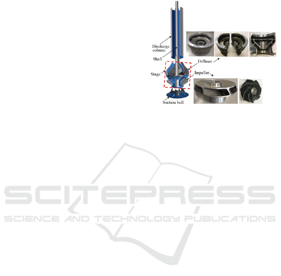
Figure 1 illustrates the main components of the
reference vertical turbine pump studied in this
research: a suction bell, an impeller, and a diffuser.
To describe the equations of the single-phase flow
(liquid flow) and the two-phase flow (solid-liquid
two-phase flow) for the flow through a vertical
turbine pump as depicted in Figure 1, the assumptions
are made. For the liquid single-phase flow, the liquid
flow is assumed to be steady-state and three-
dimensional; the liquid is considered incompressible;
the liquid is a Newtonian liquid; and the liquid
thermophysical properties are constant with the
temperature.
Figure 1: Single-stage pump components (School of
Engineering; Mbock Singock, T. A., 2018).
Moreover, for the solid-liquid two-phase flow,
the solid phase consists of dispersed solid particles;
the heat transfer and the mass transfer between
discrete and continuous phases are negligible; the
mixture of phases is heterogeneous; the solid phase is
assumed to be uniform spherical particles, and its
physical property is unchangeable; the liquid phase is
clear water; and the effects of the mass and energy
exchange between the solid phase and the liquid
phase are negligible.
2.1 Single-Phase Flow: Liquid Flow
Accounting for the assumptions for the liquid single-
phase flow, the theoretical analysis of the liquid flow
in the passages of the impeller, the diffuser vane and
the suction bell is based on the continuity and the
momentum equations (La Roche-Carrier et al., 2013;
ANSYS Inc., 2023). For the three-dimensional liquid
flow through these components as shown in Figure 1,
the continuity equations are given by:
.0∇=
U
(1)
where
()()()
()
U=U u x,y,z ,v x,y,z ,w x,y,z
is the liquid
flow velocity vector.
The momentum equations are expressed by:
.( ) .( ( ) )
∇⊗=−∇+∇∇+∇ +
+
T
eff
M
UU p U U
gS
ρμ
ρ
(2)
where p is the pressure; ρ is the density; μ
eff
is the
effective viscosity accounting for turbulence, it is
defined as
eff t
μ = μ + μ
, μ is the dynamic viscosity
and
μ
t
is the turbulence viscosity. It is linked to
turbulence kinetic energy
κ and dissipation ε; and 𝑆
⃗
represents the vector Coriolis, the centrifugal effect,
Performance Improvement of a Vertical Turbine Pump Accounting for the Solid-Water Two-Phase Flow Conditions
113

and the drag effect. It is equal to zero for the flow in
the stationary components like the diffuser and the
suction bell.
More particularly, for the flow in a rotating
impeller at a constant angular speed
ω, the source
term can be written as follows:
()
()
2
M
SxUxxr
ρω ωω
=− +
(3)
2.2 Two-Phase Flow: Solid-Liquid
Two-Phase Flow
Related to the solid-liquid two-phase flow through a
vertical turbine pump, it is highlighted that the
Sommerfeld collision model is applied to consider the
collision between particles, and the collision between
the solid particles and the wall (
ANSYS Inc., 2023;
Sommerfeld M., 1982). For that, due to the nature of the
mining rocks, the collision is assumed to be fully
elastic. To specify the drag, the Schiller Naumann
drag model is used supposing that the solid particles
are spherical, and the Reynolds number is sufficiently
large for inertial effects to dominate viscous effects.
Moreover, the dispersed phase zero equation model is
applied as the turbulence model. The wear of the
pump parts by erosion is not assessed in this study.
The volume fraction is given by:
=
i
i
V
V
ξ
(4)
where V
i
is the volume occupied by the phase i (i = α
for the liquid phase and i =
β for the solid phase); and
V is the volume containing both phases.
According to the particle model, the transfer of the
momentum between the solid particles and the water
is characterized by the interfacial area density. The
interphase contact area can be expressed as follows:
β
αβ
β
6ξ
A=
d
(5)
where d
β
is the mean diameter of spherical solid
particles and
ξ
β
is the volume fraction of the solid
phase.
To ensure that the area density is not null, the particle
model is modified and the Equation (5) becomes:
β
αβ
β
6ξ
A=
d
(6)
where
β min β max
β
β
max min β max
max
max(ξ ,ξ ) if ξ <ξ
ξ
1-ξ
max ξ ,ξ if ξ >ξ
1-ξ
=
(7)
The values of
ξ
min
and ξ
max
in Equation (7) are
respectively 10
-7
and 0.8.
Furthermore, the mass conservation equations of
the liquid and solid phases are formulated by:
()
.0∇=
ii i
U
ξρ
(8)
where i =
α for the liquid phase and i = β for the solid
phase;
ξ
i
is the volume fraction of the phase i; ρ
i
is the
density of the phase i; and U
i
is the flow velocity of
the phase i.
Adding the left member of the Equation (8) for the
solid phase and the water phase, the Equation (9) is
found:
()()
..0∇+∇=
UU
αα α ββ β
ξρ ξρ
(9)
In addition, the volume conservation equation
restraint the sum of the volume fraction of both
phases to unity at any time, as follows:
1+=
αβ
ξξ
(10)
Moreover, the momentum equations for the solid and
the liquid phases can be given by:
()
()
(
)
.
.
∇⊗=−∇+++
∇∇+∇ +
iii i ii i Mi
T
ii i i
UU p gS
UU
ξρ ξ ρ
ξμ
(11)
where p
i
is the pressure of the phase i; μ
i
is the
dynamic viscosity of the phase i;
𝑆
⃗
Mi
is the source
term vector in the context of the two-phase flow. It is
formulated as follows:
()
()
2=− +
Mi i i i
SxUxxr
ρω ωω
(12)
Additionally, the characteristics of the solid
particles in the liquid that the pump can drain in the
mining environment are not always known in
advance.
Therefore, considering that the solid particles are
dispersed, the diameter, the volume fraction and the
specific gravity of a solid particle are varied
according to the Table 1.
SIMULTECH 2024 - 14th International Conference on Simulation and Modeling Methodologies, Technologies and Applications
114
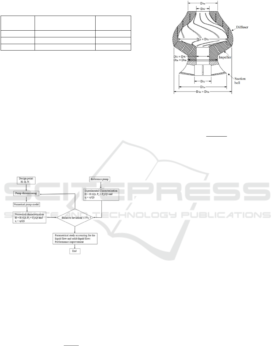
Table 1: Discrete phase parameters for dispersed solid
analysis.
Diameter
[mm]
Volume concentration
[%]
Specific
gravity [-]
1 10 1
2 20 2
3 30 3
3 DESIGN PARAMETERS OF
THE COMPONENTS OF A
VERTICAL TURBINE PUMP
The developed numerical approach to design the
impeller, the diffuser and the suction bell of a vertical
turbine pump is based on an existing physical pump
and a process of trial and error using the references
(Dicmas J. L., 1987; La Roche-Carrier et al., 2013; Peng
W. W., 2008; Stepanoff A. J., 1957)
. This approach
accounts for the operating conditions of the pump
which is the mining environment. Thus, Figure 2
shows the steps from the design point to the numerical
characterization of the vertical turbine pump.
Figure 2: Steps of the numerical characterization of the
vertical turbine pump.
Furthermore, the parameters of the impeller, the
suction bell, and the diffuser are depicted in Figure 3.
To achieve the numerical model of the vertical
turbine pump, the design point used is described by a
flow rate of 0.11 m
3
/s, a pump head of 35 m and a
rotating speed of 1785 rpm. The pump type is
determined calculating the specific speed which is
given by:
1/ 2
3/4
=
s
NQ
N
H
(13)
where Q is the flow rate, H is the pump head, and N
is the rotating speed.
Figure 3: Suction bell, impeller, and diffuser.
The corresponding dimensionless specific speed can
be expressed as follows:
()
1/2
3/4
=
ad
Q
N
gH
ω
(14)
where
ω is the angular speed.
According to the value of N
s
, the reference
vertical pump under study is Francis’s type (Peng W.
W., 2008). This geometry is classified between radial
and axial pumps. Physically, this reflects the fact that
the flow inside the Francis-type pump is semi-axial.
Moreover, the following assumptions are
formulated for the dimensioning of the impeller, the
diffuser, and the suction bell: the inlet flow in the
impeller is considered without circumferential
component; the outlet blade angle of the pump
impeller is considered as constant; and the ratio of the
inner and the outer radius of the impeller is kept
constant.
4 ELEMENT MESH, VERTICAL
TURBINE PUMP MODELING
AND BOUNDARY
Equations (1), (2), (9) and (11) resulting from the
mathematical modeling are solved numerically while
accounting for the boundary conditions and the
turbulence model by means of the ANSYS-CFX code
to obtain the distributions of the liquid flow velocity
and the pressure for the liquid single-phase flow and
the solid-liquid two-phase flow. In the cases
examined involving the pump stage, the boundary
conditions are formulated as follows: the static
pressure is given at the stage inlet, while the flow rate
is specified at the stage outlet. The frozen rotor
condition is applied for the impeller-diffuser interface
Performance Improvement of a Vertical Turbine Pump Accounting for the Solid-Water Two-Phase Flow Conditions
115
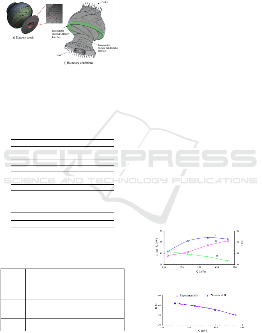
and the suction bell-impeller interface. In sum, Figure
4 shows the element mesh and the boundary
conditions for the pump model.
Figure 4: Element mesh and pump boundary conditions.
5 RESULTS AND DISCUSSION
The used properties of the 17-4PH steel (impeller,
diffuser, and shaft) and the water in this study are
indicated in Tables 2 and 3.
Table 2: Properties of the 17-4PH steel.
Young’s modulus [Pa] 1.96x10
11
Poisson ratio 0.3
Compressibility module [Pa] 1.63x10
11
Shear modulus [Pa] 7.53x10
10
Resistance coefficient [Pa] 9.2x10
8
Ductility coefficient [Pa] 10
9
Yield strength [Pa] 7.93x10
8
Ultimate tensile strength [Pa] 1.103x10
9
Densit
y
[k
g
/m³] 7750.4
Table 3: Properties of water in 25 °C.
Density [kg/m³] Kinematic viscosity [m
2
/s]
997 0.884x10
-6
Furthermore, the main reference data for the impeller,
diffuser and
suction bell
are indicated in Table 4.
Table 4: Reference data for the impeller, the diffuser and
the suction bell.
Impeller D
h
= 70 mm; D
1
= 160 mm;
D
1m
= 123 mm; D
2
= 310.6 mm;
D
2m
= 288.64 mm; D
2i
= 288.64 mm;
b
1
= 64 mm; b
2
= 38 mm; β
1
= 19°;
β
2
= 27.5°; and Z = 7.
Diffuser D
3
= 310.6 mm; D
3i
= 266.68 mm;
D
4
= 160 mm; lc = 190.9 mm;
b
3
= 45.12 mm; β
3
= 30°; β
4
= 90°; and Z
d
=8.
Suction
b
ell
D
5
= 256.17 mm; D
6
= 160 mm;
L
c
= 68, 45 mm; R
c
= 115.36 mm; and Z
c
=4.
As regards the numerical simulations performed,
three cases are analyzed for the performance
assessment of the considered vertical turbine pump:
a) the characterization and the validation of the
numerical model using water single-phase flow; b)
the effect of the solid-water two-phase flow; and c)
the effect of the diffuser vane number.
5.1 Characterization and Validation of
the Numerical Model
To characterize the developed numerical pump model
in terms of head, brake horsepower and efficiency
using the water single-phase flow, the flow rate range
from 170.25 m³/h to 520.75 m³/h are selected keeping
the other parameters constant. Figure 5 represents the
pump head, the brake horsepower and the efficiency
as a function of the flow rate. From this figure, it can
be seen the trend of the performance curves of the
vertical turbine pump. The head decreases with
increasing flow rate. The brake horsepower raises
with the augmentation of the flow rate, whereas the
efficiency raises till the best efficiency point (BEP),
then it decreases with growing flow rate. At the BEP,
the flow rate is 397.25 m³/h, the head is 35.52 m, the
brake horsepower is 50.73 kW and the efficiency is
78.54 %. Furthermore, the numerical results are
compared with the experimental results to validate the
numerical pump model. A very good agreement is
achieved for the curves of the head and the efficiency
as depicted in Figures 6 and 7 respectively. The
corresponding relative gaps in absolute value of the
comparison results as a function of the flow rate are
shown in Figure 8. Thus, the validated numerical
model is designated as a reference model for the
analysis of performance improvement accounting for
the two-phase flow of water and solid particles.
Figure 5: Head, brake horsepower and efficiency versus
flow rate.
Figure 6: Head comparison.
SIMULTECH 2024 - 14th International Conference on Simulation and Modeling Methodologies, Technologies and Applications
116
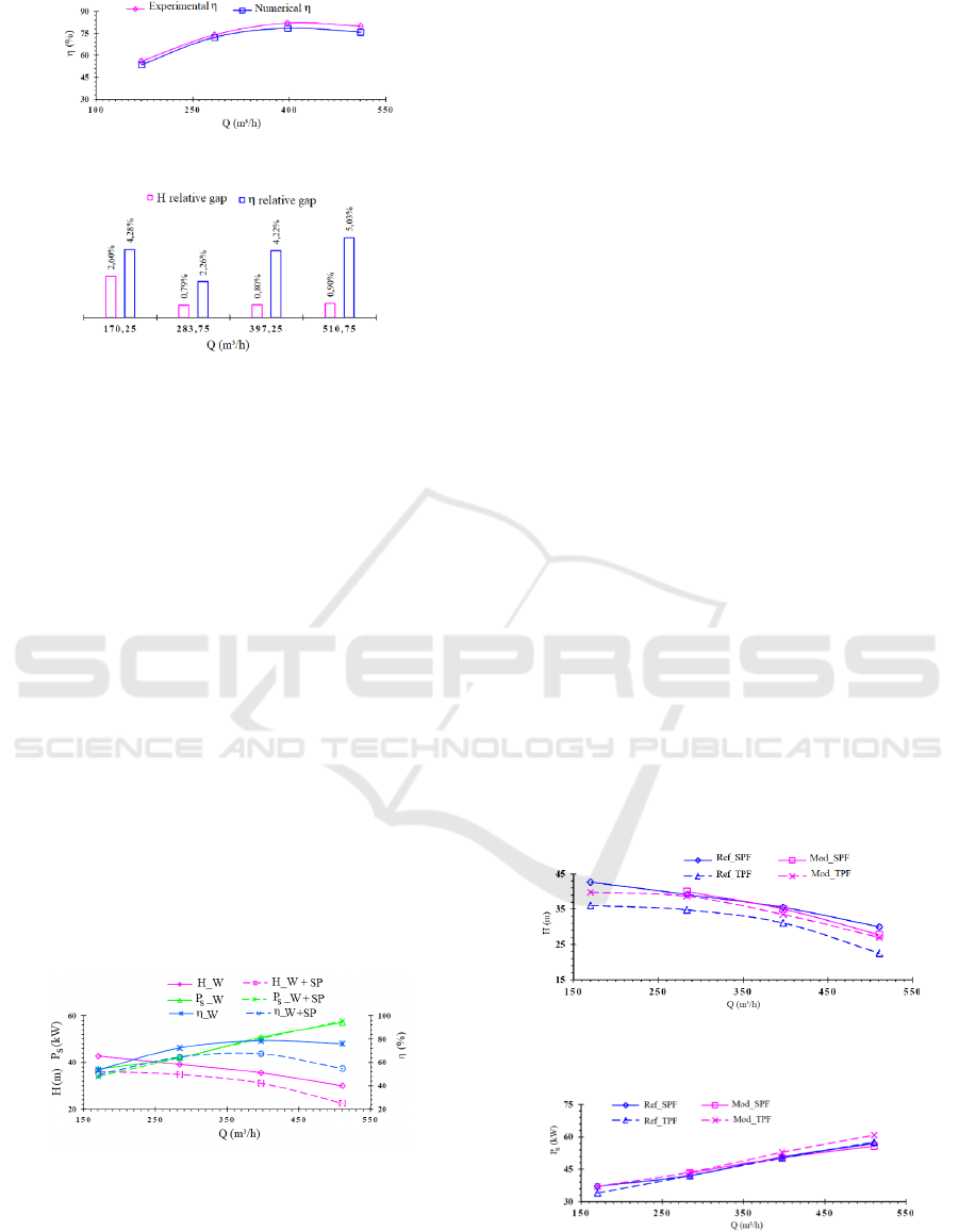
Figure 7: Pump efficiency comparison.
Figure 8: Relative gap between experimental and numerical
results.
5.2 Effect of the Solid-Water
Two-Phase Flow
To analyze the effect of the solid-water two-phase
flow on the pump head, the brake horsepower and the
efficiency, the reference model is used considering
the two-phase flow of water and solid discrete
particles. The applied values for the volume fraction
of solid particles, the solid particles diameter and the
specific gravity of the solid particles are 10 %, 1 mm
and 2, respectively. In addition, the flow rate range
from 170.25 m³/h to 520.75 m³/h are selected. Figure
9 illustrates the pump head, the brake horsepower and
the efficiency as a function of the flow rate for water
flow and the solid-water two-phase flow. From there,
it can be seen that the head and the efficiency for the
water flow are better than these for the solid-water
two-phase flow, whereas the brake horsepower is
almost identical for both flow types. The drops in the
pump head and the efficiency represent the impact of
the solid particles on the flow field in the pump.
Figure 9: Head and efficiency versus flow rate: single-phase
(W) and two-phase (W+SP) flow.
5.3 Effect of the Diffuser Vane Number
To investigate the effect of the diffuser vane number
on the pump performance accounting for the water
single-phase flow (SPF) and the solid-water two-
phase flow (TFP), the vertical turbine pump model
with 7 diffuser vanes is selected while holding the
other parameters constant for the flow rate from 280.5
m³/h to 510 m³/h. This pump model is designated as
modified model to distinguish it from the reference
model that has 8 diffuser vanes. Figs. 10-12 show the
pump head, the brake horsepower and the efficiency
as a function of the flow rate with the diffuser vane
number as a parameter. From Figure 10, it is observed
that the pump head for the solid-water two-phase flow
with the modified model is greater than that with the
reference model. Moreover, the gap between the
pump heads for the water flow with the reference and
the modified models is lower than the gap for the
solid-water two-phase flow with the reference and
modified models. In addition, Figure 11 shows that
the brake horsepower for the solid-water two-phase
flow with the modified model is slightly higher than
the brake horsepower of all other cases. Relating to
the pump efficiency, Figure 12 illustrates that the
efficiency for the solid-water two-phase flow with the
modified model is between the efficiencies for the
water single-phase flow and the solid-water two-
phase flow with the reference model. Thus,
comparing the efficiencies of the reference and the
modified models accounting for the solid-water two-
phase flow, it can be mentioned that the efficiency is
better for the modified model. This can show that the
modified model is at this level of assessment, best
suited to withstand the variations required by the
transition from water flow to solid-water two-phase
flow without any functional or installation
modification.
Figure 10: Head versus flow rate: reference and modified
models.
Figure 11: Brake horsepower versus flow rate: reference
and modified models.
Performance Improvement of a Vertical Turbine Pump Accounting for the Solid-Water Two-Phase Flow Conditions
117
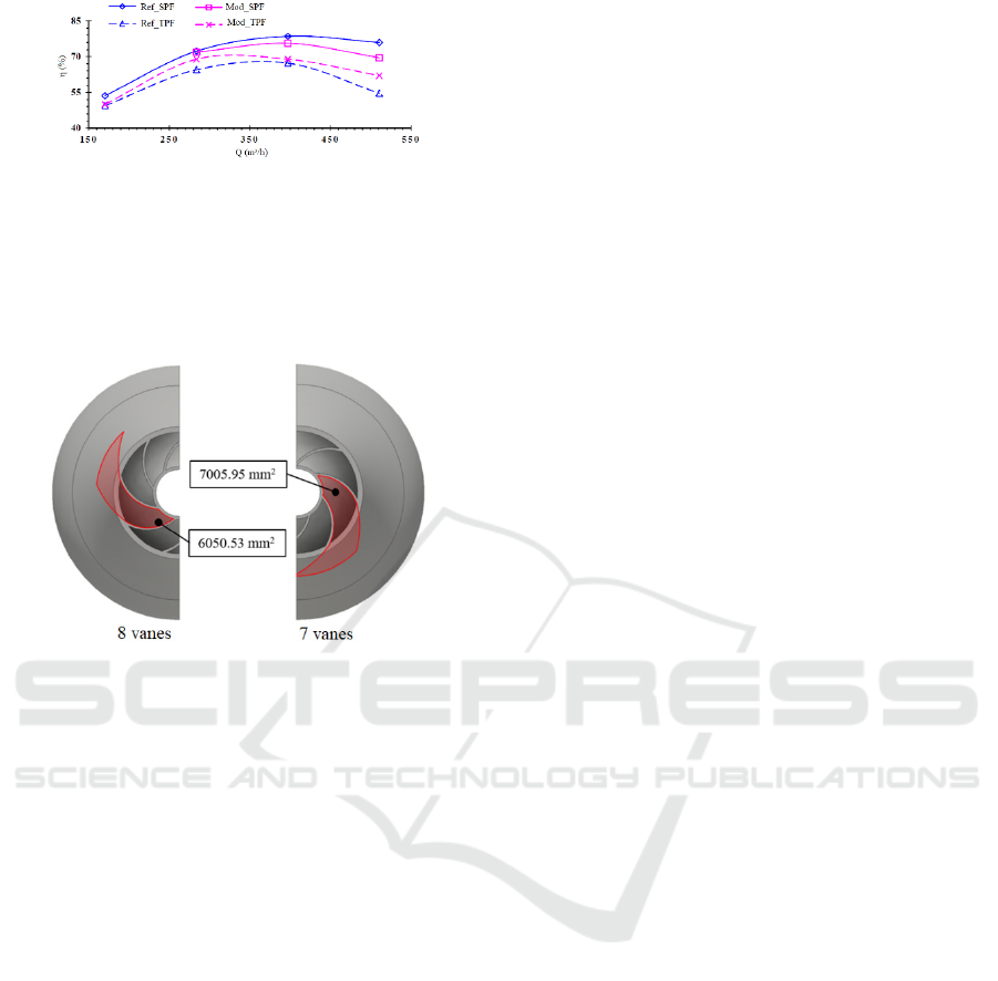
Figure 12: Efficiency versus flow rate: reference and
modified models.
In sum, it is to highlight that the use of 7 diffuser
vanes in the modified pump model leads to a
widening of the diffuser channels of 13.8 % as
indicated in Figure 13.
Figure 13: Modified diffuser channels.
6 CONCLUSIONS
This study deals with the design and the numerical
characterization of a vertical turbine pump in the
context of the performance enhancement. Based on
the design point, the numerical model of a vertical
turbine pump of Francis type is developed. By means
of the ANSYS CFX code, the pump head, the brake
horsepower and the efficiency are determined in
different operating conditions using the water single-
phase flow to obtain the reference model after
validation. A very good agreement is achieved
comparing the numerical results from the reference
model and the experimental results. Then,
simulations are accomplished with the reference
model considering the sold-water two-phase flow. It
is observed that the pump head and the efficiency for
the water two-phase flow are lower than those for the
water single-phase flow, whereas the brake
horsepower is remained almost unchanged. Thus, to
improve the performance of the reference model in
the case of the solid-water two-phase flow, the
diffuser with 7 vanes is used keeping the impeller
blade number of 7 to obtain the modified model. The
comparison of the numerical results between the
reference model and the modified model revealed an
improvement of the head and the efficiency for the
modified model. Further research work is planned to
analyze the effects of the induced forces and stresses
on the vertical turbine pump performance in the
mining environment.
ACKNOWLEDGEMENTS
The authors are grateful to the Technosub Inc.,
Industrial pumps manufacturing and distribution in
Quebec (Canada) and the Turbomachinery
laboratory
of the Engineering School of the University of
Quebec in Abitibi-Témiscamingue.
REFERENCES
ANSYS Inc., ANSYS CFX-Solver Theory Guide Release
2023 R1. Canonsburg, PA, USA, 2023.
Birajdar R. S., Keste A. A., and Gawande S. H. (2021).
Critical Hydraulic Eccentricity Estimation in Vertical
Turbine Pump Impeller to Control Vibration,
International Journal of Rotating Machinery.
Dicmas J. L. (1987). Vertical turbine, mixed flow, and
propeller pumps, McGraw-Hill Book Company New
York.
Gao Y., Cao W., Zhang Y., Cao G. and Zhao X. (2023).
Investigation of high-speed deep well pump
performance with different outlet setting angle of space
diffuser, Frontiers in Energy Research.
La Roche-Carrier N., Dituba Ngoma G., and Ghie W.
(2013). Numerical investigation of a first stage of a
multistage centrifugal pump: impeller, diffuser with
return vanes, and casing. ISRN Mechanical
Engineering, Vol. 2013, Article ID 578072, 15 pages.
Lazarkiewicz, S., TROSLANSKI, A. T. (1965). Impeller
pumps. Pergamon Press Ltd., Headington Hill Hall,
Oxford.
Mbock Singock, T. A. (2018). Conception et caractérisation
numérique d'une pompe à turbine verticale de grande
capacité. Université du Québec en Abitibi-
Témiscamingue.
Mohapatra J. N., Gujare R. R., Dabbiru S. K., Sah R.
(2023). Failure Analysis of Vertical Turbine Pump
Shaft, Journal of Failure Analysis and Prevention
(JFAP).
Nikumbe A. Y., Tamboli V. G., Wagh H. S. (2015). Modal
Analysis of Vertical Turbine Pump, International
Advanced Research Journal in Science, Engineering
and Technology.
Peng W. W. (2008). Fundamentals of turbomachinery,
John Wiley & Sons, California.
School of Engineering, Turbomachinery laboratory (E-
216), University of Quebec in Abitibi-Témiscamingue
(UQAT), www.uqat.ca.
SIMULTECH 2024 - 14th International Conference on Simulation and Modeling Methodologies, Technologies and Applications
118

Sommerfeld M. (1982). Modelling of Particle-Wall
Collisions in Confined Gas-Particle Flows,
International Journal of Multiphase Flow, 18(6), pp.
905-926.
Stepanoff A. J. (1957), Centrifugal and Axial Flow Pumps,
Theory, Design, and Application, Jonh Wiley & Sons,
New York.
Sunil P. (2022). Testing of Mixed Flow Vertical Turbine
Pump, International research journal of engineering and
technology (IRJET).
Trivedi J. B., Trivedi J., Chauhan V. (2016). Hydraulic
Analysis of Vertical Turbine Pump, INROADS- An
International Journal of Jaipur National University.
Xia Y., Maddox G., S. Lowry and Ding H. (2015), Design
and Optimization of a Vertical Turbine
Pump, Proceedings of the ASME/JSME/KSME. Joint
Fluids Engineering Conference. Volume 1: Symposia.
Seoul, South Korea. V001T33A008. ASME. DOI:
10.1115/AJKFluids2015-33233.
Performance Improvement of a Vertical Turbine Pump Accounting for the Solid-Water Two-Phase Flow Conditions
119
