
Unlocking Antenna Performance: Harnessing the Power of the
Hahn-Banach Theorem in Wireless Communication Systems
Muhammad Uzair
1 a
, Sijjad Ali
2 b
, Asad Ali
1 c
, Hamza Amir
3 d
, Rana Zaki Abdul Bari
4
,
Hamid Sharif
1 e
, Maryam Jamil
4 f
, M. Hunza
4 g
, Nabel Akram
5 h
and Sharofiddin Allaberdiev
2 i
1
College of Electronics and Information Engineering, Shenzhen University, 518060, Guangdong, China
2
College of Computer Science and Software Engineering, Shenzhen University, 518060, Guangdong, China
3
School of Media and Communication, Shenzhen University, 518060, Guangdong, China
4
College of Physics and Optoelectronic Engineering, Shenzhen University, 518060, Guangdong, China
5
School of Government, Shenzhen University, 518060, Guangdong, China
Keywords:
Antenna Design, Hahn-Banach Theorem, Optimization, Wireless Communication.
Abstract:
This paper presents a novel approach for improving the performance of the antenna in wireless communication
systems through the utilization of the Hahn-Banach Theorem. With advancements of such standards as 5G and
B5G in design-related issues, traditional methods are typically inadequate. Applying the Hahn-Banach Theo-
rem results in a strong mathematical framework that augments several vital antenna parameters including gain,
efficiency, bandwidth, and radiation patterns. The approach takes solutions from limited to large design spaces,
allowing the search for new configurations within tight constraints. Results show substantial advancement in
antenna performance, creating better, more reliable progressions. This interdisciplinary method connects the-
oretical mathematics with the engineering solutions making a great step forward for practical communication
technologies. This guarantees excellent linearity and overall performance which is very important for wireless
communication signal integrity, impacting future antenna technology and wireless communication research
and development.
1 INTRODUCTION
Antennas are integral to modern wireless communi-
cation systems, supporting diverse applications from
mobile communications to IoT devices (Alexiou and
Haardt, 2004). As we transition to 5G and beyond
(B5G), demand for faster data rates and lower la-
tency intensifies (Hong et al., 2017). Traditional an-
tenna designs struggle to meet the advanced require-
ments of B5G networks, such as multi-band operation
and massive MIMO capacities (Jamil et al., 2010).
Consequently, researchers are turning to mathemati-
cal optimization methods like the Hahn-Banach The-
orem to improve antenna performance (Aharon and
a
https://orcid.org/0009-0002-6812-7799
b
https://orcid.org/0000-0002-9141-8837
c
https://orcid.org/0009-0004-5399-0156
d
https://orcid.org/0009-0008-6306-9415
e
https://orcid.org/0009-0006-9695-4600
f
https://orcid.org/0009-0008-2067-4113
g
https://orcid.org/0000-0003-3604-7874
h
https://orcid.org/0009-0002-8815-6124
i
https://orcid.org/0000-0001-6087-8024
Nemirovski, 2001). These methods offer systematic
frameworks to explore design parameters and con-
straints, identifying optimal configurations (Alateewe
and Nagy, 2024).
They allow for the evaluation of various intri-
cate performance criteria and trade-offs, resulting in
Pareto-optimal solutions (Wang et al., 2024). In ad-
dition, uncertain reality environment management is
resolved by mathematical design approach (Cheragh-
inia et al., 2024). Many modern antenna techniques
such as metamaterials and reconfigurable antennas
are incorporated into it (Kumar et al., 2021), improv-
ing antenna performance in B5G networks.
Our methodology allows for the creation of effec-
tive wireless systems for multiple B5G uses, URIIC,
and big IoT links (Singh et al., 2024). It also guides
development of sophisticated signal processing algo-
rithms and network protocols designed for B5G sys-
tems (Sufyan et al., 2023). In general, utilization of
mathematical optimization strengthens antenna devel-
opment, stimulates innovation, and defines an infras-
tructure of communication networks.
340
Uzair, M., Ali, S., Ali, A., Amir, H., Bari, R., Sharif, H., Jamil, M., Hunza, M., Akram, N. and Allaberdiev, S.
Unlocking Antenna Performance: Harnessing the Power of the Hahn-Banach Theorem in Wireless Communication Systems.
DOI: 10.5220/0012795100003758
Paper published under CC license (CC BY-NC-ND 4.0)
In Proceedings of the 14th International Conference on Simulation and Modeling Methodologies, Technologies and Applications (SIMULTECH 2024), pages 340-347
ISBN: 978-989-758-708-5; ISSN: 2184-2841
Proceedings Copyright © 2024 by SCITEPRESS – Science and Technology Publications, Lda.

2 ANTENNA DESIGN METHODS
2.0.1 Empirical and Numerical Methods
Methods are practical for antenna designers who will
work with these designs on and on, refining them in
the process through experience. On the other hand,
for complex antenna structures and detailed electro-
magnetic analysis requirements, numerical methods
such as Finite-Difference Time-Domain (FDTD) sim-
ulations (Thaher et al., 2020) are invaluables. They
offer accurate and rapid analyses, supplementing em-
pirical approaches and extending the toolkit of the de-
signer for best performance.
∇ × E = −
∂B
∂t
, ∇ × B = µ
0
J + µ
0
ε
0
∂E
∂t
(1)
Numerical methods, illustrated in (Zhu et al.,
2023), take standard antenna configurations such as
dipoles and Yagi-Uda arrays as the basic geome-
tries for further modification. FDTD simulations dis-
cussed in (Zhu et al., 2023) enable analytical accu-
racy through discretization of space and time domains
for solving Maxwell’s equations to present a thor-
ough modeling of antenna performance parameters on
a computational grid;
∇ × E = −
∂B
∂t
(2)
This equation presents the curl form of electric
field (E), which is equal to the negative rate of change
of the magnetic flux density (B). It demosntrates how
a time-varying magnetic field gives rise to an electric
field, which is a basic principal of electromagnetic in-
duction.
∇ × H = J +
∂D
∂t
(3)
The magnetic field of the curl (H) is created
among electric current (J) and the rate of change of
the electric displacement field (D). This equation
generalizes Ampere’s Law to include displacement
current, which considers changes in the electric
field (Mittra, 2018). FDTD iterative updates electric
and magnetic fields at discrete points to model
wave propagation and electromagnetic phenomena,
making it indispensable in modern antenna design.
For instance, updating electric and magnetic fields
relies on their respective curls. This discretization is
typically represented as:
E
x
(i, j, k)
n+1
= E
x
(i, j, k)
n
− ∆t
H
z
(i, j+1,k)
n
−H
z
(i, j,k)
n
∆y
−
H
y
(i, j,k+1)
n
−H
y
(i, j,k)
n
∆z
H
x
(i, j, k)
n+1
= H
x
(i, j, k)
n
+ ∆t
E
z
(i, j+1,k)
n
−E
z
(i, j,k)
n
∆y
−
E
y
(i, j,k+1)
n
−E
y
(i, j,k)
n
∆z
(4)
where E
x
and H
x
is the electric field component
and magnetic field component, n is the time step in-
dex, and i, j, k are the indices of the grid points in the
x, y, and z directions, respectively. Where ∆t is the
time step increment, and ∆x, ∆y, and ∆z are the step
increments in each direction in space.
The empirical methods lay solid basis for antenna
design, particularly for conventional types of anten-
nas. The power of numerical methods, such as FDTD
in solving Maxwell’s equation in practically any ge-
ometry, is crucial in designing the modern complex
antenna systems(Alexiou and Haardt, 2004).
2.0.2 Genetic Algorithms (GA)
GA are modeled after biological evolution, using
mechanisms like selection, crossover, and mutation.
Population of potential designs in the antenna design
is evolved for several generations until the optimal so-
lutions are found.
Fitness Function in GA:
f (x) = Performance(x) (5)
where x represents the antenna parameters.
2.0.3 Particle Swarm Optimization (PSO)
PSO simulates the social behavior of birds or fish to
optimize a problem. Particles move through the so-
lution space, adjusting their trajectories based on per-
sonal and communal experiences(Sehrai et al., 2020).
PSO Equations:
Position Update:
x
i
(t + 1) = x
i
(t) + v
i
(t + 1) (6)
Velocity Update:
v
i
(t + 1) =w · v
i
(t) + c
1
· r
1
· (p
best
− x
i
(t))
+ c
2
· r
2
· (g
best
− x
i
(t))
(7)
we considered the case where i is a particle in-
dex, x
i
an d v
i
are positions and velocities, p
best
and
g
best
are best known positions, r
1
, r
2
are two random
numbers, and c
1
, c
2
are learning factors. They are es-
pecially efficient in regards to problem spaces which
consist of several dimensions for example than tradi-
tional methods could not be so practical (Thaher et al.,
2020).
Unlocking Antenna Performance: Harnessing the Power of the Hahn-Banach Theorem in Wireless Communication Systems
341

3 METHODOLOGY
3.1 Hahn-Banach Theorem
The Hahn-Banach theorem extends bounded linear
functionals from subspaces to the entire space while
preserving their norms, playing a crucial role in math-
ematics and various fields (Ben-Tal and Nemirovski,
2021). Its significance lies in functional analysis and
finds applications in optimization, information trans-
mission, and antenna design. This ensures continuous
operationalization of metric functions on normed vec-
tor spaces without altering their norms, a characteris-
tic vital for numerous applications;
| f (x)| ≤ C||x||, ∀x ∈ U (8)
F(x) = f (x), ∀x ∈ U (9)
|F(x)| ≤ C||x||, ∀x ∈ V (10)
here, f denotes the functional on U, F is its exten-
sion on V , and C is a constant. Provide the descrip-
tion of the antenna design problem with specifications
(directivity, bandwidth, radiation pattern, interference
rejection); use the Hahn-Banach Theorem for strate-
gic extension in order to overcome performance lim-
itations with the design constraints (Abdullah et al.,
2019).
3.2 Problem Formulation
Design a compact antenna for portable 5G devices,
optimizing gain, bandwidth, linearity, and adhering to
strict weight constraints;
• Gain (G): Aim for a high gain to ensure robust
signal reception and transmission over distances,
targeting a minimum gain of 6 dBi.
• Bandwidth (BW ): The antenna must support
a wide bandwidth to accommodate the 5G fre-
quency range, specifically from 3.3 GHz to 3.8
GHz, to cover various 5G bands.
• Linearity: Ensure high linearity to reduce signal
distortion, which is crucial for maintaining the in-
tegrity of high-speed data transmission in 5G net-
works.
• Weight (W ): Due to the portable nature of the
device, the antenna’s weight should not exceed 20
grams.
3.3 Solution Approach Using the
Hahn-Banach Theorem
Proposing a novel approach using the Hahn-Banach
Theorem to tackle design challenges in compact,
high-performance antennas for portable 5G devices,
optimizing gain, bandwidth, linearity, and adhering to
weight constraints.
3.3.1 Defining Design Space and Performance
Metrics
Let V represent the vector space of all possible an-
tenna designs, and U ⊆ V the subspace (Ben-Tal and
Nemirovski, 2021) of initially feasible designs. The
performance metrics are defined as functions map-
ping designs to real values representing gain (G),
bandwidth (BW ), linearity (L), and weight (W ).
The theorem is applied to extend performance
evaluation functionals (Jamil et al., 2010) from U to
the entire space V , facilitating the exploration of in-
novative designs. This extension ensures that:
| f (x)| ≤ p(x), ∀x ∈ U → ∀x ∈ V
The expression | f (x)| ≤ p(x), ∀x ∈ U → ∀x ∈V sig-
nifies that the condition imposed by p(x) on f (x) in
the subspace U is preserved as f (x) is extended across
the entire space V . where as,
• f (x): Represents a functional that evaluates the
performance of an antenna design x, such as its
gain, efficiency, or bandwidth.
• U: Denotes the initial subspace of feasible de-
signs, satisfying basic performance criteria or
constraints.
• V : Represents the entire design space, includ-
ing more innovative or unconventional designs be-
yond those in U.
• p(x): Defines a bound for the performance eval-
uation functional f (x), ensuring that the evalua-
tion does not exceed certain physical, regulatory,
or performance-related limits.
The Hahn-Banach Theorem expands antenna de-
sign optimization possibilities while maintaining per-
formance within specified bounds (Banks and Ku-
nisch, 2012). Systematic search enables the identifi-
cation of enhanced performance measures within set
constraints (Jiang et al., 2019).
4 MATHEMATICAL MODELING
The mathematical modeling of antenna graph consists
of the example of the antenna’s electromagnetic char-
acteristics through various mathematical equations.
Key factors of this modeling included radiation pat-
tern, impedance, benefit, and efficiency.
SIMULTECH 2024 - 14th International Conference on Simulation and Modeling Methodologies, Technologies and Applications
342

Radiation Pattern. The radiation pattern is repre-
sented by means of:
E(θ, φ) = f (θ, φ) (11)
where E(θ, φ) denotes the electric field intensity at an-
gles θ and φ.
Impedance. Antenna impedance, combining resis-
tance and reactance, is given by:
Z = R + jX (12)
where Z is the impedance, R is resistance, and jX is
reactance.
Gain. The gain of an antenna is defined as:
G =
4πU(θ, φ)
P
in
(13)
where G is the gain, U(θ, φ) the radiation intensity,
and P
in
the input power.
Efficiency. Efficiency is the ratio of the power radi-
ated to the power input:
η =
P
rad
P
in
(14)
where η is efficiency, P
rad
is radiated power, and P
in
is input power.
Bandwidth. The bandwidth of an antenna is ex-
pressed as:
BW = f
2
− f
1
(15)
where BW is bandwidth, and f
1
, f
2
are the lower and
upper frequency limits, respectively. Mathematical
modeling is crucial in antenna design, providing in-
sights into performance and aiding in the optimiza-
tion of antenna characteristics. This modeling forms
the basis for simulation and analysis in the antenna
design process.
4.1 Performance Specifications
The antenna design must meet the following specifi-
cations:
• Desired Gain: Minimum of 06 dBi.
• Bandwidth: Operate effectively from 3.3 GHz to
3.8 GHz.
• Radiation Pattern: Ensure consistent perfor-
mance across orientations, focusing on omni-
directional or directional patterns.
• Interference Rejection: Incorporate features to
minimize electromagnetic interference.
The main challenge is optimizing antenna gain
within size and weight limits(Abdullah et al., 2019),
demanding a delicate balance between performance
and dimensions, necessitating innovative design and
strategic optimization techniques.
4.2 Functional Analysis
Apply the Hahn-Banach Theorem to extend a
bounded linear functional from a subspace (e.g., spe-
cific antenna configuration) to the entire vector space
(e.g., design space)(Ben-Tal and Nemirovski, 2021).
This extension facilitates advanced optimization of
key antenna characteristics, enabling efficient utiliza-
tion of complex design spaces.
4.3 Functional Extensions Using
Hahn-Banach Theorem
4.3.1 Radiation Pattern
Simplified Functional in U:
f
RP
(x) = Integration(E(θ, φ;x)) (16)
Extended Functional in V:
F
RP
(y) = ExtendedIntegration (E(θ, φ; y)) (17)
4.3.2 Impedance
Simplified Functional in U:
f
Z
(x) = CalculateImpedance(x) (18)
Extended Functional in V:
F
Z
(y) = ExtendedCalculateImpedance(y) (19)
4.3.3 Gain
Simplified Functional in U:
f
G
(x) = CalculateGain(x) (20)
Extended Functional in V:
F
G
(y) = ExtendedCalculateGain(y) (21)
4.3.4 Efficiency
Simplified Functional in U:
f
E
(x) =
P
rad
(x)
P
in
(x)
(22)
Extended Functional in V:
F
E
(y) =
P
rad
(y)
P
in
(y)
(23)
The objective is to find an antenna design y
∗
in V that
optimizes the extended functional, considering real-
world constraints.
Unlocking Antenna Performance: Harnessing the Power of the Hahn-Banach Theorem in Wireless Communication Systems
343
4.4 Mathematical Formulation for
Optimizing y
∗
in V
We aim to find an optimal antenna design y
∗
in V ,
which involves solving the following optimization
problem:
4.4.1 Extended Functional Formulation
Find y
∗
in V such that: (24)
maxF
total
(y) (25)
subject to:
F
RP
(y) ≥ Threshold
RP
, (26)
F
Z
(y) ≈ Desired Impedance, (27)
F
G
(y) ≥ Threshold
G
, (28)
F
E
(y) ≥ Threshold
E
, (29)
and other real-world constraints.
Where:
• F
total
(y) is a combined functional representing
overall performance.
• F
RP
, F
Z
, F
G
, F
E
are extended functionals for radi-
ation pattern, impedance, gain, and efficiency re-
spectively.
• Thresholds and desired values are set based on
real-world requirements.
4.4.2 Optimization Criteria
• The optimization seeks to maximize F
total
(y)
while meeting all individual functional require-
ments.
• This process involves balancing various antenna
characteristics within the constraints of the com-
plex design space V .
Through advanced mathematical equations and the
application of the Hahn-Banach Theorem, the pro-
cess of optimizing antenna design in a complex space
V addresses both theoretical and practical aspects,
leading to the determination of an optimal design y
∗
(Banks and Kunisch, 2012).
Implement numerical simulations to validate the
results obtained through the Hahn-Banach-based op-
timization.
5 RESULTS ANALYSIS
Applying the Hahn-Banach Theorem to antenna de-
sign and optimization has yielded significant im-
provements. This mathematical framework has been
leveraged to observe benefits through advanced sim-
ulations, enhancing the helical signal’s creation, dis-
tortion correction, and overall performance.
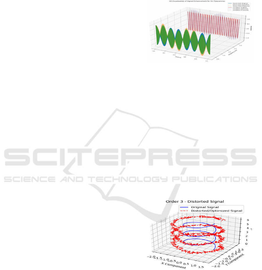
Figure 1: Radiation Pattern of a Nonlinear Antenna Array.
Magnitude in Decibels.
Figure 1, illustrates the enhancement process for
two distinct 5G frequency bands—Sub-6 GHz and
mmWave—showcasing signal optimization,A statis-
tical analysis comparing signal-to-noise ratio (SNR)
and mean squared error (MSE) before and after opti-
mization demonstrates the effectiveness of the Hahn-
Banach theorem in reducing interference and enhanc-
ing signal quality. Table 1, lists the unique time and
frequency settings used within the evaluation.
In signal processing (Table 3) linearity ensures the
output remains proportional to input, critical for sig-
nal integrity and avoiding nonlinear distortions which
can alter signal quality. The enhancement process
aims to minimize such distortions, enhancing linear-
ity as demonstrated by improved SNR and reduced
MSE in the enhanced signal, indicating a closer align-
ment to the original signal.
Figure 2: Comparison of Original and Distorted Signals for
a Dipole Antenna at Third Harmonic Order.
Figure 2 shows the original signal (blue line) and
the noise signal (red dashed line) before optimization.
The stable, undisturbed signal is represented by the
consistent helical shape of the blue line, while the red
dashed line indicates significant deviation, signaling
distortion. As signal order increases, distortion and
randomness worsen, directly impacting antenna effi-
ciency and causing receiver lag, resulting in increased
SIMULTECH 2024 - 14th International Conference on Simulation and Modeling Methodologies, Technologies and Applications
344

Table 1: Summary of Signal Characteristics Before and After Enhancement for Sub-6 GHz and mmWave 5G Frequencies.
Parameter Value Description
Frequencies (f) {’Sub-6 GHz’: 3.5 x
10
9
, ’mmWave’: 28 x
10
9
}
Frequency bands for 5G in GHz, including Sub-6
GHz and mmWave frequencies.
Time (t) np.linspace(0, 1, 1000) Time vector used for signal simulation, spanning from
0 to 1 second with 1000 points.
distortion frequency
(fz)
2 x 10
6
Frequency of the distortion signal in Hz.
distortion level
(Lmin)
Random (0.3 to 0.6) Level of the distortion added to the original signal,
adjusted for visibility.
Table 2: Comparison of Original and Distorted/Optimized Signals for a Third-Order Harmonic.
Parameter Value Description
Time (t) 0.1 to 100 A vector representing time from 0 to 1 second with
1000 sample points.
Frequencies (f) [1, 2, 3] A list of frequencies (in Hz) for which the signals will
be simulated.
distortion level
(Lmin)
Random (0.3) The level of distortion applied to the original signal.
Order (Harmonics) 3 The harmonic order used to modify the frequency
component of the original signal.
interference. Higher signal order complexity poses
optimization challenges, with the distorted signal de-
viating significantly from the original signal, leading
to degraded efficiency.
As indicated in Table 2, Figure 2 illustrates the
contrast between the pre-optimization noisy signal
(red dashed line) and the stable original signal (blue
line). The chaotic pattern of the red line signifies dis-
tortion, while the constant helix of the blue line de-
notes an unchanged signal. This distortion degrades
antenna performance, exacerbating interference and
receiver delay, particularly as signal order increases,
set to 3 according to Table 2. Python simulations
confirm that higher order signals present greater chal-
lenges to signal fidelity during optimization.
Figure 3: Radiation Pattern comparison of the Baseline and
Enhanced Antenna Array.
The Figure 3, shows a blue curve for the clean sig-
nal and a red dashed curve for the same signal after it
has been enhanced. The optimization, influenced by
the Hahn-Banach Theorem, effectively reduces noise,
bringing the red signal closer to the original blue one,
demonstrating the theorem’s utility in improving sig-
nal clarity at receiver end.
Figure 4: Signal Distortion in a Dipole Antenna Across
three Orders.
The Figure 4, depict 3D plots showing how the
signal amplitude of a dipole antenna changes over
time, labeled as ”Time” and ”Signal Amplitude.”
Each plot contrasts an original signal in solid lines
with a noise added signal version in dashed lines
across three orders:
Order 1: The blue lines indicate a clear deviation
of the distorted signal from the original, highlighting
noticeable distortion.
Order 2: The green lines show less deviation than
Unlocking Antenna Performance: Harnessing the Power of the Hahn-Banach Theorem in Wireless Communication Systems
345
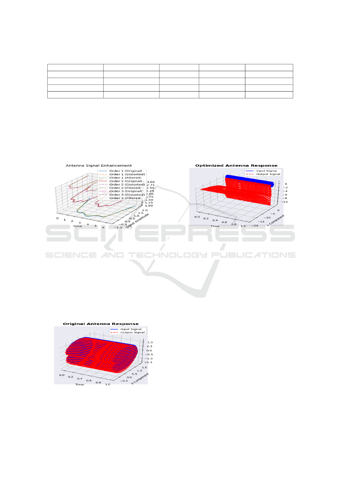
Table 3: Comparison of SNR and MSE Metrics for Different Frequency Bands.
Frequency Band Metric Original Distorted Enhanced
Sub-6 GHz SNR (dB) 16.96 8.70 13.12
MSE - 0.0675 0.0244
mmWave SNR (dB) 16.96 8.88 13.19
MSE - 0.0648 0.0240
Order 1, suggesting less distortion.
Order 3: The orange lines display the greatest
deviation, implying the most significant distortion.
These visualizations illustrate the signal’s degradation
with increasing order, providing insight into the an-
tenna’s performance and signal degradation when it
was receive at receiver ends. The original signals in-
formation is missing or undetectable at this distortion.
Figure 5: Signal processing of an antenna at three harmonic
orders, showing original (solid), distorted (dashed), and en-
hanced (dotted) signal states.
The Figure 5, displays curves for original, dis-
torted, and enhanced signals across three frequency
levels, known as orders. With each order representing
a higher frequency, the distortion grows more severe
and severe that cause for the mismatched information
at receiver ends, yet the enhanced signal—improved
using the Hahn-Banach Theorem that will enhance
the signal at higher frequencies and mitigate the noise
and closely mirrors the original curve, indicating ef-
fective noise reduction for clearer communication.
Figure 6: 3-D Visualization of Antenna response: tracking
input vs. Output alerts over time.
The Figure 6, is a 3D plot that compares the input
and output signals of an antenna. The solid blue line
represents the consistent input signal, while the red
dashed line shows how the antenna has altered this
signal, indicating the antenna’s response over time.
The vertical gaps between the lines suggest changes
in signal strength due to noise/distortion, and the hori-
zontal spread may point to timing or phase shifts. This
visualization helps assess the antenna’s performance.
Figure 7: Enhancing sign Integrity: Hahn-Banach
Theorem-driven Optimization of Antenna Output.
The second Figure 7, titled ”Optimized Antenna
Response” shows a 3D plot with a solid blue sur-
face for the input signal and a larger, more varied
red dashed surface for the output signal, indicating
significant changes made during optimization. The
culmination of results given in Table 3 highlights the
proposed method’s substantial enhancement of signal
linearity, marked by reduced distortion and noise, af-
firming the technique’s proficiency in preserving sig-
nal integrity across diverse 5G frequencies. Using the
Hahn-Banach Theorem inside the signal optimization
process targets to limit these variations enhancing the
antenna’s performance by way of making the output
more carefully fit the input.
6 CONCLUSION, LIMITATIONS
AND ISSUES, FUTURE WORK
The Hahn-Banach Theorem offers a functional analy-
sis approach that enhances antenna design, accelerat-
ing 5G development and broadening application hori-
zons from eMBB to URLLC and mMTC. This break-
through calls for an evolution in wireless communi-
cation, elimination of the current hurdles, and setting
SIMULTECH 2024 - 14th International Conference on Simulation and Modeling Methodologies, Technologies and Applications
346

of new connectivity standards. Such designs are inte-
gral to supporting key 5G applications including au-
tonomous vehicles, smart manufacturing, and exten-
sive IoT networks, underscoring their importance in
future wireless technologies.
6.1 Limitations and Issues
• Complexity: Implementing Hahn-Banach
Theorem-based designs requires advanced math-
ematical expertise, potentially limiting practical
application.
• Scalability: Adapting designs to real-world sce-
narios, especially in urban environments, may
pose challenges.
• Resource Demands: Computational requirements
could hinder deployment in resource-constrained
settings.
6.2 Future Work
• Optimization: Develop tailored optimization al-
gorithms to streamline design processes.
• Machine Learning Integration: Explore integrat-
ing machine learning for adaptive antenna sys-
tems.
• Experimental Validation: Conduct real-world val-
idation to ensure performance across environ-
ments.
ACKNOWLEDGEMENTS
We sincerely thank each author, participant, and col-
league for their invaluable contributions to this article.
REFERENCES
Abdullah, M., Kiani, S. H., and Iqbal, A. (2019). Eight el-
ement multiple-input multiple-output (mimo) antenna
for 5g mobile applications. IEEE Access, 7:134488–
134495.
Aharon, B. and Nemirovski, A. (2001). Lectures on modern
convex optimization. Siam.
Alateewe, H. T. and Nagy, S. (2024). Optimizing the geom-
etry of a cylindrical dielectric resonator antenna (cdra)
in combination with the design of a microstrip patch
antenna to improve antenna efficiency. Periodicals of
Engineering and Natural Sciences, 12(1):5–18.
Alexiou, A. and Haardt, M. (2004). Smart antenna tech-
nologies for future wireless systems: trends and chal-
lenges. IEEE communications Magazine, 42(9):90–
97.
Banks, H. T. and Kunisch, K. (2012). Estimation techniques
for distributed parameter systems. Springer Science &
Business Media.
Ben-Tal, A. and Nemirovski, A. (2021). Lectures on mod-
ern convex optimization 2020. SIAM, Philadelphia.
Cheraghinia, M., Shahid, A., Luchie, S., Gordebeke, G.-
J., Caytan, O., Fontaine, J., Van Herbruggen, B.,
Lemey, S., and De Poorter, E. (2024). A comprehen-
sive overview on uwb radar: Applications, standards,
signal processing techniques, datasets, radio chips,
trends and future research directions. arXiv preprint
arXiv:2402.05649.
Hong, W., Jiang, Z. H., Yu, C., Zhou, J., Chen, P., Yu,
Z., Zhang, H., Yang, B., Pang, X., Jiang, M., et al.
(2017). Multibeam antenna technologies for 5g wire-
less communications. IEEE Transactions on Antennas
and Propagation, 65(12):6231–6249.
Jamil, A., Yusoff, M. Z., and Yahya, N. (2010). Current is-
sues and challenges of mimo antenna designs. In 2010
International Conference on Intelligent and Advanced
Systems, pages 1–5. IEEE.
Jiang, H., Si, L.-M., Hu, W., and Lv, X. (2019). A symmet-
rical dual-beam bowtie antenna with gain enhance-
ment using metamaterial for 5g mimo applications.
IEEE Photonics Journal, 11(1):1–9.
Kumar, P., Ali, T., and Pai, M. M. (2021). Electromag-
netic metamaterials: A new paradigm of antenna de-
sign. IEEE Access, 9:18722–18751.
Mittra, R. (2018). Some challenges in millimeter wave an-
tenna designs for 5g. In 2018 International Sympo-
sium on Antennas and Propagation (ISAP), pages 1–2.
IEEE.
Sehrai, D. A., Abdullah, M., Altaf, A., Kiani, S. H.,
Muhammad, F., Tufail, M., Irfan, M., Glowacz, A.,
and Rahman, S. (2020). A novel high gain wideband
mimo antenna for 5g millimeter wave applications.
Electronics, 9(6):1031.
Singh, R., Kaushik, A., Shin, W., Di Renzo, M., Sciancale-
pore, V., Lee, D., Sasaki, H., Shojaeifard, A., and Do-
bre, O. A. (2024). Towards 6g evolution: Three en-
hancements, three innovations, and three major chal-
lenges. arXiv preprint arXiv:2402.10781.
Sufyan, A., Khan, K. B., Khashan, O. A., Mir, T., and Mir,
U. (2023). From 5g to beyond 5g: A comprehensive
survey of wireless network evolution, challenges, and
promising technologies. Electronics, 12(10):2200.
Thaher, R. H. et al. (2020). Design and analysis microstrip
antenna with reflector to enhancement gain for wire-
less communication. Bulletin of Electrical Engineer-
ing and Informatics, 9(2):652–660.
Wang, J., Chen, K., Yang, H., and Zhang, L. (2024). Ensem-
ble deep learning enabled multi-condition generative
design of aerial building machine considering uncer-
tainties. Automation in Construction, 157:105134.
Zhu, L., Ma, W., and Zhang, R. (2023). Modeling and per-
formance analysis for movable antenna enabled wire-
less communications. IEEE Transactions on Wireless
Communications.
Unlocking Antenna Performance: Harnessing the Power of the Hahn-Banach Theorem in Wireless Communication Systems
347
