
Optimal Design of a Variable-Pitch Axial Flow Fan by Applying
Optimization Algorithm to Design, Through-Flow Analysis and
CFD Simulation Methods
Chan Lee
1
, Jimin Choi
1
, Jiseok Hwang
1,
*
, Hyeongjin Lee
2,†
, Sangyeol Lee
3
and Sang Ho Yang
3,‡
1
Department of Mechanical Engineering, University of Suwon, 17 Wauangil, Hwaseong, Republic of Korea
2
PIDOTEC, 05854, A-309 MSTATE, 114 Beobwon-ro, Songpa-gu, Seoul, Republic of Korea
3
Samwon E&B, 233 Jeongwangchun-ro, Shiheung, Republic of Korea
Keywords: Axial Flow Fan, Blade Design, CFD (Computational Fluid Dynamics), Efficiency, Optimization,
Through-Flow Analysis.
Abstract: In order to develop a variable-pitch axial fan, an optimal three-dimensional fan blade is designed by using the
2-stage design optimization strategy to combine aerodynamic fan design program, CFD technique, and
optimization algorithm. At the 1
st
stage of fan design optimization, the aerodynamic fan design program of
this study is the FANDAS code where the chord length, setting angle, and camber angle of the fan blade are
considered as design variables, and the performance, efficiency, and power of the fan are predicted by
applying the through-flow analysis method to the designed fan. By applying a optimization algorithm to the
FANDAS program, a three-dimensional fan blade shape is optimized and constructed for maximizing fan
efficiency. At the 2
nd
stage of fan design optimization, CFD analysis method is also applied on the optimized
fan from the first design optimization study, and additional design optimization for the blade setting angles is
conducted by applying an optimization algorithm to the CFD model and simulation results. Furthermore the
total pressure, efficiency, and power characteristic curves of the fan according to the variable-pitch operation
conditions are calculated by applying the CFD technique to the final optimal fan model obtained through the
2-stage design optimization processes. From the CFD results on the characteristic curves of optimal fan, it is
found that the optimal fan model of this study shows the highest efficiency of 91% at the design point,
maintains high efficiency level of 80% in a wide flow range through variable-pitch operation.
1 INTRODUCTION
Axial flow fans are key flow components in various
ventilation, air conditioning, and energy systems in
industrial, commercial, and residential fields. A
recent technical issue of axial fans is to improve fan
performance and efficiency due to global climate
change and carbon neutrality trends. Variable pitch
axial flow fans have the advantage of maintaining
high efficiency even in a wide flow range by adjusting
the fan blade setting angle and reducing power by 15-
20% compared to conventional fans (Wright, 2020).
In a high efficiency axial fan design, since the air flow
on the surface of the fan blade greatly affects the
aerodynamic performance and efficiency of the fan,
*
https://www.suwon.ac.kr
†
https://www.pidotech.com
‡
https://www.sebco.co.kr
optimizing the geometric shape of 3D fan blade is a
very important task of the fan designer (Kim, 2022).
For this reason, in recent years, a lot of research has
been conducted on optimizing fan blade design for
high efficiency fan development (Angelini, 2017;
Edward, 2021).
Therefore, in this paper, a new variable-pitch axial
flow fan design is performed by applying the
optimization algorithm to the fan blade design
program and CFD calculation process to maximize
fan efficiency. In this study, when fan design
variables are given as inputs, a three-dimensional fan
blade shape is constructed through a design program,
and the total pressure, efficiency, and power of the fan
are calculated as fan’s key performance indices by
Lee, C., Choi, J., Hwang, J., Lee, H., Lee, S. and Yang, S.
Optimal Design of a Variable-Pitch Axial Flow Fan by Applying Optimization Algorithm to Design, Through-Flow Analysis and CFD Simulation Methods.
DOI: 10.5220/0012798200003758
Paper published under CC license (CC BY-NC-ND 4.0)
In Proceedings of the 14th International Conference on Simulation and Modeling Methodologies, Technologies and Applications (SIMULTECH 2024), pages 363-369
ISBN: 978-989-758-708-5; ISSN: 2184-2841
Proceedings Copyright © 2024 by SCITEPRESS – Science and Technology Publications, Lda.
363
applying through-flow analysis or CFD method to the
designed fan. And this design and analysis process is
combined with an optimization algorithm to obtain
optimal fan design. The optimal fan designed by this
method is verified using CFD simulation, and the
advantages of this optimal fan in terms of energy
saving are identified by predicting the performance,
efficiency, and power characteristics of the fan
according to the variable pitch operation.
2 BACKGROUD ON FAN DESIGN
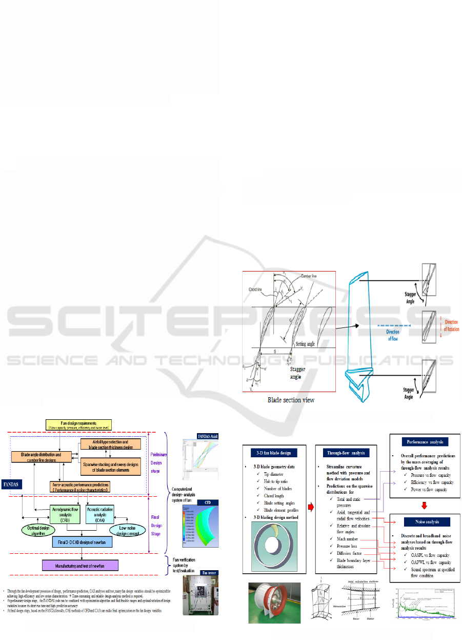
In Figure 1 showing general fan development
procedure, final fan design can be obtained through a
series of processes of geometry design, CFD analyses,
manufacturing and testing. Traditionally, 3D fan
blade shape has been made by design programs based
on aerodynamic theories (e.g., the FANDAS code),
and CFD techniques have been used to verify the flow
and performance of such designed fans. And most fan
design optimizations have also been performed using
design programs. However, because of recent
remarkable advances in optimization techniques and
computing power, fan design optimization problems
can be handled not only with design programs but
also with CFD simulation methods, even though there
are many fan design variables. For this reason, the
present study proposes two-stage design optimization
strategy for the fan development procedure of Figure
1, where optimization algorithm is sequentially
combined with design program (the FANDAS code,
1
st
stage) and CFD technique (the ANSYS CFX code,
2
nd
stage).
Figure 1: General fan development procedure.
3 FAN DESIGN PROGRAM WITH
THE PERFORMANCE
PREDICTION BY
THROUGH-FLOW ANALYSIS
The present study employs a fan blade design
program which has been developed and verified in the
university laboratory of the present authors
(FANDAS, 2023). In this study, chord length, stagger
angle and camber angle are considered as design
variables to determine blade section as shown in Figure
2. The camber line of the blade section is determined by
using single circular arc to meet given camber angle,
and NACA 6308 airfoil thickness distribution is
added onto the camber line to construct blade element
profile (refer to Figure 2). Once blade section elements
are determined from the three design variables, 3D fan
blade geometry is constructed by the stacking of the
blade section elements along blade span height from
hub to tip.
Figure 2: Main fan blade design parameters.
Figure 3: Through-flow analysis procedure.
SIMULTECH 2024 - 14th International Conference on Simulation and Modeling Methodologies, Technologies and Applications
364
After 3D fan blade shape is determined, the design
program can also predict the performance, power and
efficiency of designed fan by a through-flow analysis
method. Figure 3 shows the performance prediction
procedure of the present fan design program. The
FANDAS code can predict the performance, power
and efficiency of designed fan by using the through-
flow analysis method of the streamline curvature-
computing scheme for the pitch-averaged radial
equilibrium equation of flow motion with flow
deviation and total pressure loss models (Lee, 2021).
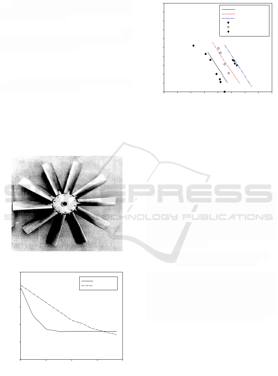
In this study, the through-flow analysis method of
the FANDAS code is applied to a variable pitch axial
flow fan of Figure 4, which is designed with camber
and stagger angle distributions in Figure 5. Here
setting angle is defined as 90
o
– stagger angle. As
shown in Figure 6, the present performance
predictions are favorably matched with the test results
(van der Spuy, 1997/2002) at different fan-blade pitch
angles when the setting angle of blade hub is set to 25,
35 or 45 deg.
Figure 4: Rotor blades of a variable pitch fan.
Figure 5: Camber and setting angle distributions.
Figure 6: Performance curves of variable pitch fan.
4 2-STAGE FAN DESIGN
OPTIMIZATION STUDY
4.1 1
st
Stage: Optimal Fan Design
Using Through-Flow Analysis
Method
In the 1
st
stage design optimization, objective
function is defined as the total pressure efficiency of
fan, which is calculated by the through flow analysis
method of the design program, the FANDAS code.
Design variables of this study are the camber angle
(
), the setting angle () and the chord length () of
fan impeller blade (refert to Figure 7), so optimization
problem is formulated as
with design constraints in Table 1
where the camber angle, the stagger angle and the
chord length are defined as design variables at three
blade span locations of hub (0% span), mid-span
(50% span) and tip (100% span) in Figure 8, and
their functions of spanwise direction, r, are
constructed in the form of parabolic curves using the
defined design variables at those three locations.
Blade span length[mm]
0 100 200 300 400
Camber and setting angles[deg.]
0
10
20
30
40
50
: Camber angle
: Setting angle
Flow capacity[CMS]
0 1 2 3 4 5 6 7 8
Fan static pressure[Pa]
0
50
100
150
200
250
300
350
400
450
500
: Prediction( 25 deg )
: Prediction( 35 deg )
: Prediction( 45 deg )
: Test( 25 deg )
: Test( 35 deg )
: Test( 45 deg )
Optimal Design of a Variable-Pitch Axial Flow Fan by Applying Optimization Algorithm to Design, Through-Flow Analysis and CFD
Simulation Methods
365
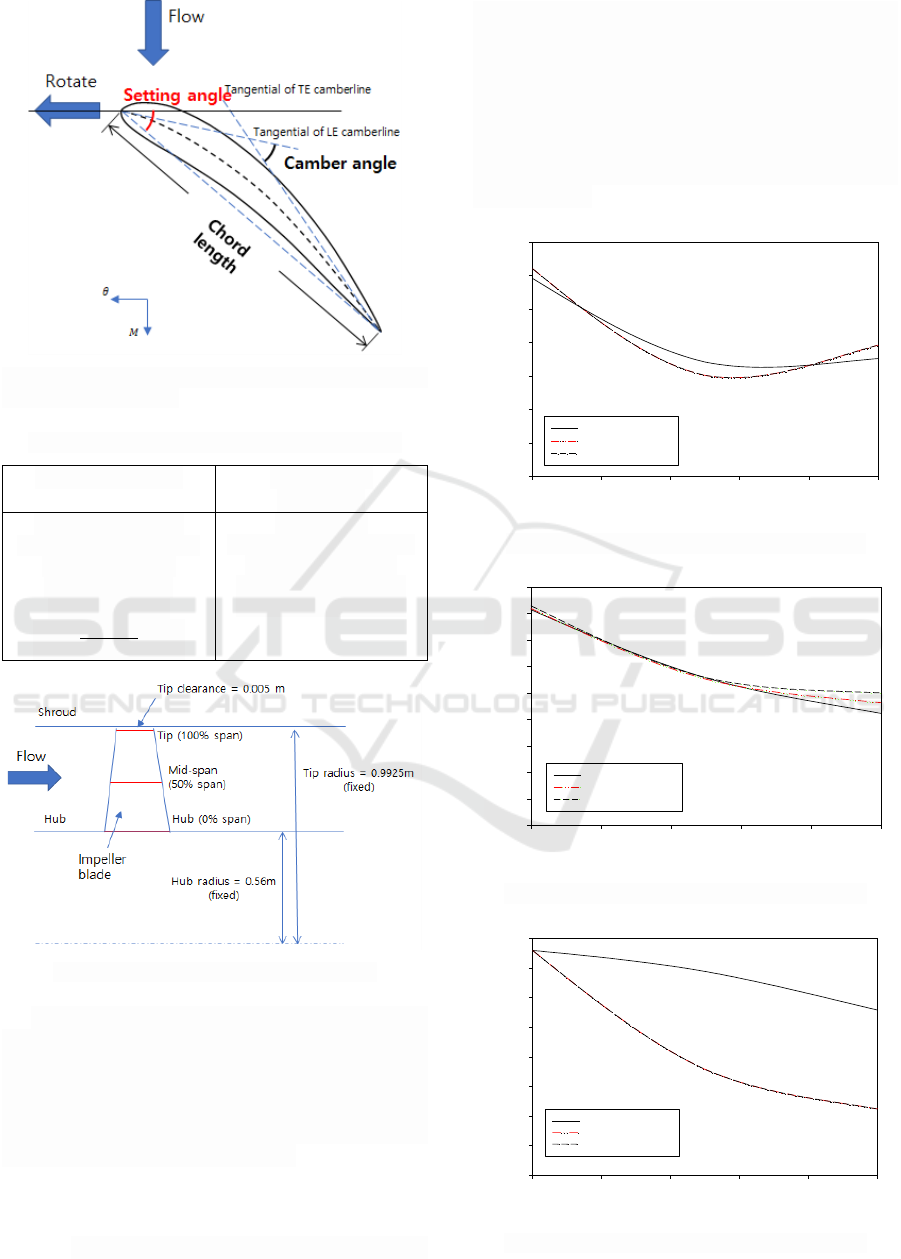
Figure 7: Definitions of camber, setting angles and chord
length of impeller blade.
Table 1: Design constraints for design optimization.
Design constraints
Fixed design
parameters
RPM = 1200
Tip diameter =1,985[mm]
Hub/tip ratio = 0.564
No. of blades (
= 12
Tip clearance = 5 [mm]
Figure 8: Meridional view of fan rotor blade.
The determined camber, stagger angles and chord
lengths are used as input data of the through-flow
analysis method for the efficiency prediction of the
designed fan model. Optimization algorithm used in
this study is Hybrid Metaheuristic Algorithm
(PIDOTEC, 2021), which is coupled with the design
program with through-flow analysis.
Optimal design variables are obtained and shown
in Figures 9-11 after several iterative calculations are
carried out. Comparing the initial and the 1
st
optimal
results, the optimal camber angles at hub and tip are
somewhat higher than the initial ones while the
optimal setting angle at hub is higher than the initial
one. The optimal chord lengths at mid-span and tip is
smaller than the initial ones and its magnitude
decreases from hub to tip. It is noted that initial design
is made by free vortex method (McKenzie: 2017).
The efficiency of optimal fan model, 87.2% is
improved by 3.6 % when compared with the initial
design, 83.6%.
Percent blade span height, (r-r
hub
)/(r
tip
-r
hub
)x100
0 20 40 60 80 100
Camber angle [deg.]
0
5
10
15
20
25
30
35
: Initial design
: 1st optimal design
: 2nd optimal design
Figure 9: Camber angle distributions of fan blade.
Percent blade span height, (r-r
hub
)/(r
tip
-r
hub
)x100
0 20 40 60 80 100
Setting angle [deg.]
0
5
10
15
20
25
30
35
40
45
: Initial design
: 1st optimal design
: 2nd optimal design
Figure 10: Setting angle distributions of fan blade.
Percent blade span height, (r-r
hub
)/(r
tip
-r
hub
)x100
0 20 40 60 80 100
Chord length [mm]
100
125
150
175
200
225
250
275
300
: Initial design
: 1st optimal design
: 2nd optimal design
Figure 11: Chord length distributions of fan blade.
SIMULTECH 2024 - 14th International Conference on Simulation and Modeling Methodologies, Technologies and Applications
366
4.2 2
nd
Stage: Optimal Fan Design
Using CFD Method
In the 2
nd
stgae design optimization, optimization
algorithm is applied to CFD modelling and simulation
method for further efficiency improvement from the
1
st
stage optimal design model. Since the through-
flow analysis method used in the 1
st
stage optimal
design is a one-dimensional method, it is impossible
to predict the three-dimensional flow effects and
pressure losses such due to spanwise mixing, so the
application of the CFD method can be considered to
predict these three-dimensional flow effects and
pressure losses and reflect them in the fan design.
However, since numerical calculations by the CFD
method require more time and effort than through
flow analysis, it is not suitable for optimization
handling many design variables, so only three setting
angles out of the nine design variables considered in
the 1
st
stage optimization study are considered as
design variables in this study, and the remaining
camber angle and cord length are fixed as the optimal
design result in the 1
st
step. Objective function is also
defined as the total pressure efficiency of fan, which
is determined by CFD calculations of the ANSYS
CFX code.
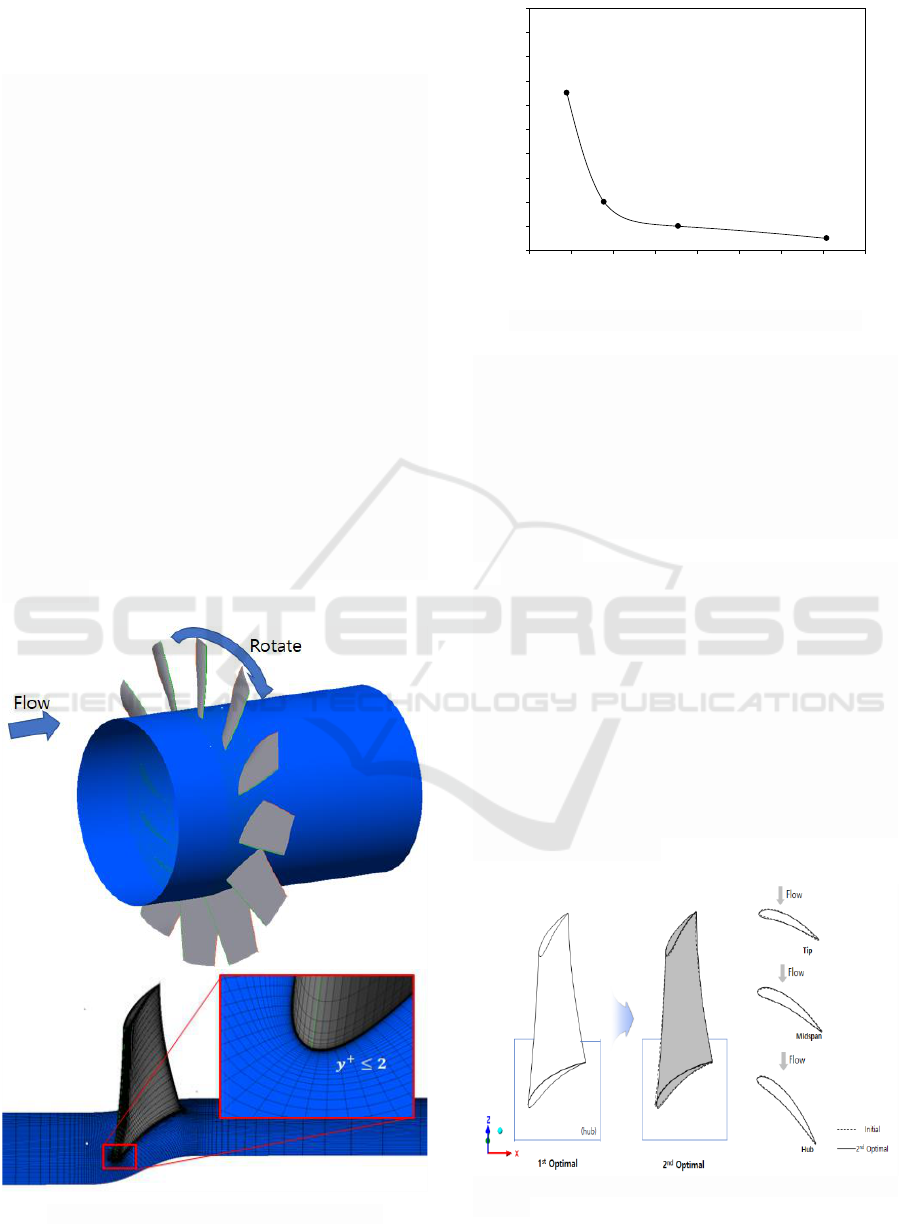
Figure 12: Mesh system of rotating fan blades.
Number of elements [x10
3
]
0 200 400 600 800 1000 1200 1400 1600
Total pressure [kPa]
16.20
16.22
16.24
16.26
16.28
16.30
16.32
16.34
16.36
16.38
16.40
Figure 13: Grid dependency test of mesh system.
Structured mesh systems on the flow domain between
nearby fan blades are constructed by uing the Turbo
grid program (refer to Figure 12). Mesh quality and
grid dependency tests are conducted on mesh systems
with different number of elements, and the mesh
system with 708x10
3
elements shows very good grid
convergence index of 4.42x10
-4
on total pressure
predcition, so is used in this optimization study (refer
to Figure 13).
Through the 2
nd
design optimization on setting
angles with CFD simulations, the optimal setting
angle distribution is obtained, and the shape change
of the 3D blade is shown in Figure 14. The setting
angle near the tip is somewhat larger than that of the
1
st
optimal design and is increasing by up to 2
degrees. The fan efficiency by the 2
nd
optimal design
is calculated to be 91.4%, which is 4.2%
improvement compared to the 1
st
optimization result.
Figure 15 compares the efficiencies of the initial, the
1st and the 2nd optimal design models, and shows
7.8% efficiency improvement through 2 stage design
optimization processes.
Figure 14: 3-D Fan blade shapes of 1
st
and 2
nd
optimal
models.
Optimal Design of a Variable-Pitch Axial Flow Fan by Applying Optimization Algorithm to Design, Through-Flow Analysis and CFD
Simulation Methods
367
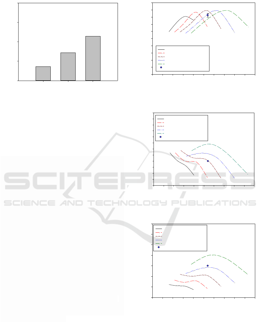
Initial 1st optimal 2nd optimal
Total efficiency [%]
80
85
90
95
100
Figure 15: Fan efficiency comparison.
5 CFD ANALYSIS ON THE
OPTIMAL FAN MODEL
UNDER VARIABLE-PITCH
OPERATION
The changes of the total pressure, efficiency and
power of the optimal fan model according to the flow
rate are calculated using the CFD method while
change of the setting angle relative the optimal one
(pitch angle) is from -10 to +10 degree. The optimal
fan model is considered as the case where a cambered
plate type guide vane is installed behind the impeller
blade obtained through this optimization study. For
reference, in this study, the manufacturing of the
optimal design model is in progress, so the CFD
results can’t be compared with the test results. As
shown in the efficiency curve of Figure 16, it can be
seen that the efficiency can be maintained as high as
80% or more even under flow conditions that are less
or more than the design flow rate by adjusting the
pitch angle. From the total pressure curves of Figure
17, when the pitch angle is fixed as 0 degree, surge
occurs at a small flow rate, but by reducing the pitch
angle, surge is avoided and stable operation is
possible. Figure 18 shows that the fan can be operated
with relatively low power even in small flow
conditions through the change of the pitch angle. In
addition, when the flow rate increases, increasing the
pitch angle improves efficiency and reduces power
(refer to Figures 16 and 18).
Flow capacity [m
3
/min]
0 1000 2000 3000 4000 5000 6000 7000 8000 9000 10000
Total efficiency [%]
0
10
20
30
40
50
60
70
80
90
100
: CFD (Pitch change = -10 deg.)
: CFD (Pitch change = -5 deg.)
: CFD (Pitch change = 0 deg.)
: CFD (Pitch change = +5 deg.)
: CFD (Pitch change = +10 deg.)
: Design target (FEG 85)
Figure 16: Efficiency curves of the optimal fan model under
variable-pitch operation.
Flow capacity [m
3
/min]
0 1000 2000 3000 4000 5000 6000 7000 8000 9000 10000
Total pressure [Pa]
0
500
1000
1500
2000
2500
3000
3500
4000
4500
5000
5500
6000
: CFD (Pitch changle = -10 deg.)
: CFD (Pitch change = -5 deg.)
: CFD (Pitch change = 0 deg.)
: CFD (Pitch change = +5 deg.)
: CFD (Pitch change = +10 deg.)
: Design target
Figure 17: Total pressure curves of the optimal fan model
under variable-pitch operation.
Flow capacity [m
3
/min]
0 1000 2000 3000 4000 5000 6000 7000 8000 9000 10000
Power [kW]
0
100
200
300
400
500
600
700
: CFD (Pitch change = -10 deg.)
: CFD (Pitch change = -5 deg.)
: CFD (Pitch change = 0 deg.)
: CFD (Pitch change = +5 deg.)
: CFD (Pitch change = +10 deg.)
: Design target
Figure 18: Power curves of the optimal fan model under
variable-pitch operation.
SIMULTECH 2024 - 14th International Conference on Simulation and Modeling Methodologies, Technologies and Applications
368

6 CONCLUSIONS
The present study proposes a design optimization
strategy and procedure of axial flow fan, where
optimization algorithm is applied to fan design
models with the through-flow analysis method of
design program at the 1
st
stage and CFD method at the
2
nd
stage. Design optimization problems of axial flow
fan are formulated and solved with multiple design
variables and constraints. Through the 1
st
and the 2
nd
stage des+ign optimizations of fan rotor blade, fan
efficiency is improved by 3.6 % and 4.2%
respectively. Furthermore, under variable-pitch
operation, the final optimal fan is shown to be
operated with high efficiency over wider flow
capacity range.
ACKNOWLEDGMENTS
This work was supported by the Korea Institute of
Energy Technology Evaluation and Planning
(KETEP) grant funded by the Korea government
Ministry of Trade, Industry & Energy (MOTIE),
Republic of Korea.
(No. 2021202080026).
REFERENCES
Angelini, G., Bonanni, T., Corsini, A., Delibra, G., Tieghi,
L. and Volponi, D. (2017). Optimization of an axial fan
for air cooled condensers, Energy Procedia, Vol. 126,
pp.754-761
Edward, D.R., Fanny, B.C. and Jean, C.B. (2021).
Optimization of a high pressure industrial fan, ASME
Turbo Expo 2021 proceedings, Vol.1
Kyungwon Tech. (2023). FANDAS code user manual
Kim, S.W., Choi, B.L., Choi, D.H., Lee, C. and Yang, S.H.
(2022). A study on a screening method for
dimensionality reduction of large fluid machine
optimization problems, KSFM Journal of Fluid
Machinery, Vol.25, pp.48-54
Lee, C. (2021). A performance prediction method of the
axial flow fans with blade sweep, KSFM Journal of
Fluid Machinery, Vol.24, pp.24-29
McKenzie, A.B. (1997). Axial Flow Fans and
Compressors: Aerodynamic Design and Performance,
Ashgate
PIDOTEC. (2021). PIAnO code user manual
van der Spuy, S. J. (1997). The Design of a Low-Noise
Rotor-Only Axial Flow Fan Series, Master of
Engineering Thesis, Department of Mechanical
Engineering, University of Stellenbosch
van der Spuy, S.J. and von Backstrom, T.W. (2002).
Performance of rotor-only axial fans designed for
minimum exit kinetic energy, R&D Journal, Vol.18, pp.
63-69
Wright, T. and Gerhart, P. M. (2020) Fluid Machinery:
Performance, Analysis and Design, CRC Press, 2
nd
edition
Optimal Design of a Variable-Pitch Axial Flow Fan by Applying Optimization Algorithm to Design, Through-Flow Analysis and CFD
Simulation Methods
369
