
Modelling and Simulation-Based Evaluation of Twinning Architectures
and Their Deployment
Randy Paredis
1 a
and Hans Vangheluwe
1,2 b
1
University of Antwerp, Department of Computer Science, Middelheimlaan 1, Antwerp, Belgium
2
Keywords:
Twinning, Digital Twin, Variability Modelling, Simulation, Software Architecture, DEVS, Performance
Analysis.
Abstract:
The Twinning paradigm –subsuming Digital Models, Digital Shadows and Digital Twins– is a powerful en-
abler for analyzing, verifying, deploying and maintaining complex Cyber-Physical Systems (CPSs). Through-
out the (currently quite ad-hoc) creation of such systems, a plethora of choices impacts the functionality and
performance of the realized Twinning system comprised of the actual system under study and its twin. The
choices that are made have a high impact on the required investment when creating the twin, most notably on
the development time and deployment cost. This is especially true when multiple iterations are needed to find
the most appropriate level(s) of abstraction and detail, architecture, technologies and tools. As a core con-
tribution, this work follows a Model-Based Systems Engineering methodology: before realizing a Twinning
architecture, Discrete EVent system Specification (DEVS) models for deployed architecture alternatives are
constructed and simulated, to evaluate their suitability. A simple use-case of a ship moving in one dimension
is used as a running example.
1 INTRODUCTION
Digital Twins (DTs) appear in a variety of domains
(Dalibor et al., 2022), and not without reason. DTs
address many industrial needs, such as anomaly
detection, condition monitoring, predictive mainte-
nance, optimization, etc. Yet, despite their omnipres-
ence, many different and sometimes contradicting
definitions of the term “Digital Twin” exist.
We therefore introduce the concept of “Twin-
ning”, spanning the entire spectrum between Mod-
elling and Simulation, and Internet of Things; thus
subsuming Digital Models, Digital Shadows, Digital
Twins, Physical Models, Physical Twins, etc.
Twinning connects a System under Study (SuS
– also called an Actual Object (AO)) with a corre-
sponding Twin Object (TO), a model in some appro-
priate formalism (and its simulator/executor) of that
SuS (Grieves, 2014). Note that the AO can be phys-
ical (e.g., a machine) or digital (e.g., software). Sim-
ilarly, the TO can be digital or physical. The former
is generally considered a “Digital Twin” and the latter
a
https://orcid.org/0000-0003-0069-1975
b
https://orcid.org/0000-0003-2079-6643
an “Analog Twin” (Paredis et al., 2021).
When considering Twinning, the core idea is that
the models in the TOs are continually kept “in sync”
with their corresponding AO, ensuring some form of
equivalence (Madni et al., 2019). This allows replac-
ing analyses on the AO(s) by virtual analyses on the
TO(s), when (for instance) data is missing due to fail-
ing sensors. Also, using both AO and TO information
has its uses. For example when data from the AO and
the TO deviate. This may be indicative of an anomaly
in the AO’s operation, though this may also be due
to the TO model being used outside its validity range
(Van Acker et al., 2024).
Commonly, twins are built to satisfy a specific set
of goals and/or requirements pertaining to Properties
of Interest (PoIs). This is also referred to as the pur-
pose of a twin (Dalibor et al., 2022). (Qamar and
Paredis, 2012) define a “property” as the “descrip-
tor of an artifact”. Hence, it is a specific concern
of that artifact (i.e., a system), which is either logical
(e.g., the implementation of cruise control uses a PID-
controller) or numerical (e.g., there are two engines
on a ship). Some of these properties can be computed
(or derived from other, related artifacts), or specified
(by a user). PoIs consider the specific system proper-
170
Paredis, R. and Vangheluwe, H.
Modelling and Simulation-Based Evaluation of Twinning Architectures and Their Deployment.
DOI: 10.5220/0012865300003758
Paper published under CC license (CC BY-NC-ND 4.0)
In Proceedings of the 14th International Conference on Simulation and Modeling Methodologies, Technologies and Applications (SIMULTECH 2024), pages 170-182
ISBN: 978-989-758-708-5; ISSN: 2184-2841
Proceedings Copyright © 2024 by SCITEPRESS – Science and Technology Publications, Lda.

ties that are of concern to certain stakeholders. PoIs
can thus be used in the formalisation of the stakehold-
ers’ requirement(s).
For many products, multiple variants exist. This
is also the case for Twinning architectures. Vari-
ants have commonalities and variations. For instance,
multiple ships of the same type might have different
engines. Or, alternatively, a single ship might have
two twins that focus on different aspects: one on the
motor’s power consumption and another on the wear
and tear of the hull. Different configurations at these
variation points are called features. The set of all vari-
ants is called a product family.
To quantitatively evaluate and compare different
conceptual and deployment architectures for the dif-
ferent requirements, these alternatives are explicitly
modelled and simulated. We use the Discrete EVent
simulation System (DEVS) (Zeigler, 1984; Zeigler
et al., 2018) formalism as it is expressive enough to
model an entire deployed Twinning architectures.
The paper is structured as follows. Section 2 in-
troduces the basic concepts used in the paper. Sec-
tion 3 identifies three stages at which variability oc-
curs when constructing a twin. It presents a workflow
that must be traversed when creating a twin, borrow-
ing aspects from the IIRA architecture framework (In-
dustry IoT Consortium, 2022). The core contribution,
the explicit modelling and simulation of Twinning ar-
chitecture alternatives, is outlined in section 4. This is
illustrated using a simple example of a ship moving in
1D in section 5. Section 6 presents related work and
finally, section 7 concludes the paper, and sketches
some future work.
2 BACKGROUND
Multi-Paradigm Modelling (MPM) advocates to ex-
plicitly model all relevant aspects of a system us-
ing the most appropriate views and modelling lan-
guage(s), at the most appropriate level(s) of abstrac-
tion, using the most appropriate methods, techniques,
frameworks and tools (Mosterman and Vangheluwe,
2004).
In the following, two appropriate modelling for-
malisms that we shall use are briefly introduced.
2.1 Variability Modeling
A common way to deal with variability is to use Fea-
ture Modelling (Kang et al., 1990). A Feature Tree
(also known as a Feature Model or Feature Diagram)
is a tree-like diagram that depicts all features of a
product in groups of increasing levels of detail. At
each level, the Feature Tree indicates which features
are mandatory and which are optional. It can also
identify causality between features of the same or dif-
ferent groups (i.e., “if feature A is present, then fea-
ture B must also be present”), as well as more com-
plex constraints. When constructing (also known as
configuring) a specific product in a product family,
one simply has to traverse the Feature Tree, starting
from the root. In each group, a set of features is se-
lected, after which the feature tree is further traverse
downwards. This results in a specific configuration
(or feature selection) that uniquely identifies the de-
sired product.
In this paper, variability modelling is used to cap-
ture the many possible goals of Twinning.
2.2 DEVS
DEVS is a modular discrete-event formalism that
consists of basic components, called Atomic DEVS
(denoted by a 7-tuple ⟨X ,Y,S,δ
int
,δ
ext
,λ,ta⟩). Mul-
tiple Atomic DEVS can be combined into a Coupled
DEVS model, which can be hierarchically reused in
other Coupled DEVS (Zeigler, 1984; Zeigler et al.,
2018). We use so-called “classic” DEVS (as opposed
to parallel DEVS).
Each DEVS model has a set of input events X and
a set of output events Y , often grouped into ports.
The internal behaviour of an Atomic DEVS is defined
by its sequential state set S and an internal transi-
tion function δ
int
: S → S which specifies internal state
changes after a time advance ta : S → IR
+
0,+∞
. Before
applying δ
int
, the output function λ : S → Y produces
output event(s). When an external input is received,
the external transition function δ
ext
: Q × X → S (with
Q = {(s,e)|s ∈ S, 0 ≤ e ≤ ta(s)}) determines the new
model state. The elapsed time e is the time since the
last internal transition.
Multiple DEVS models can be (recursively) com-
bined into a networked structure, in the form of a
Coupled DEVS ∆ = ⟨X
∆
,Y
∆
,D, M
i
,I
i
,Z
i, j
,select⟩. X
∆
and Y
∆
are the input and output sets of this coupled
model. D identifies the set of component references,
and M
i
the model component i, ∀i ∈ D. The set of
influencees of component i (∀i ∈ D ∪ {∆}, i ̸∈ I
i
) is
denoted as I
i
. The translation function Z
i, j
is given
by Z
∆, j
: X
∆
→ X
j
; Z
i,∆
: Y
i
→ Y
∆
; and Z
i, j
: Y
i
→ X
j
(∀i ∈ D ∪ {∆}, j ∈ I
i
). Z
i, j
is used to translate event
types over connections. Finally, the tie-breaking func-
tion select : 2
D
→ D deterministically selects a sin-
gle component i ∈ D to have its internal transition if
multiple components are due to transition at the same
time.
DEVS is highly suitable for modular modelling
Modelling and Simulation-Based Evaluation of Twinning Architectures and Their Deployment
171
and simulation of dynamic systems. It is also a tar-
get language for semantics preserving transforma-
tion from a plethora of other modelling languages,
making it a kind of “simulation assembly language”
(Vangheluwe, 2000).
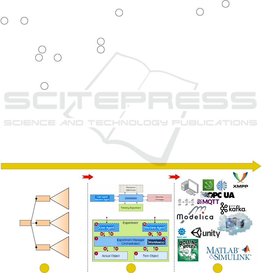
3 THE THREE STAGES
To aid in the creation of Twinning systems, a generic
workflow is used, based on the IIRA Architecture
Framework (Industry IoT Consortium, 2022) and the
ISO/IEC 12207 standard (Singh, 1996). This is illus-
trated in Figure 1. There are three main stages, A ,
B , and C . These three stages allow for the creation
of a twin for the specified requirements.
Between each of the stages, a dependency (trace-
ability) graph identifies which parts of B rely on
which parts of A and which parts of C rely on
which parts of B and A .
3.1 Goal Feature Modeling
The first stage, A (“Properties of Interest in the
Problem Space”), represents the requirement elicita-
tion. It is meant to answer why a twin must be con-
structed.
In the literature, multiple studies exist on the most
common Twinning requirements (Dalibor et al., 2022;
Van der Valk et al., 2020; Jones et al., 2020; Wanas-
inghe et al., 2020; Minerva et al., 2020). Based on
these sources, a large but nonetheless non-exhaustive
feature tree was constructed in our earlier work (Pare-
dis et al., 2021; Paredis et al., 2024).
We identify three main sub-trees in the problem
space for which specific requirements can be identi-
fied: the goals, usage contexts and quality assurance
as per (Kang and Lee, 2013).
The “goals” focus on the purpose of the twin (Dal-
ibor et al., 2022). This specifies what the Twinning
architecture needs to achieve. The “usage context”
identifies requirements pertaining to the usage and/or
user(s) of the twin. Finally, “quality assurance” speci-
fies the requirements that constrain the twin on a more
technical level.
These requirements have a major impact on both
the required architecture (column B ), as well as
the deployment (column C ). Therefore the require-
ments should be identified first. The IIRA Architec-
ture Framework calls this identification a usage view-
point.
Note that this feature tree does not select the de-
sired PoIs, but rather the desired requirements that
have an impact on the PoIs. For instance: a possible
goal for a ship is Anomaly Detection of the velocity.
The velocity of the vessel is the PoI, and “Anomaly
Detection” a goal-level requirement.
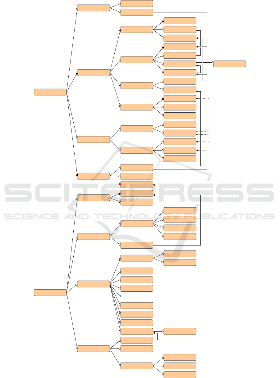
Figure 2 shows a non-exhaustive sub-tree of
(Kang and Lee, 2013)’s “Goals” and “Quality As-
surance”. Connections with filled circles identify
mandatory features. Connections with open circles
represent optional features. The full arrows identify
dependencies and the dashed arrows denote optional
dependencies.
Note that, due to space constraints, the full tree
cannot be shown (in particular the “Usage Context”
is omitted) and that not all features are represented
here. The figure is given for illustration purposes. For
clarity, “Self-*” subsumes “Self-Adaptation”, “Self-
PROPERTIES OF INTEREST
IN THE PROBLEM SPACE
DESIGN
(CONCEPTUAL) ARCHITECTURES
DEPLOYMENT
Goals
PoIs Context
Quality
WORKFLOWS
A B C
Figure 1: Generic workflow for creating twinning architectures.
SIMULTECH 2024 - 14th International Conference on Simulation and Modeling Methodologies, Technologies and Applications
172
Goal
Purpose
Design
Virtual Proptotyping
Variation Analysis
Design Space Exploration
Operation
Data Allocation
Memorization
Data Recording
Knowledge Collection
Data Processing
Data Analysis
Verification & Validation
Consistency Monitoring
State Estimation
Behaviour Prediction
Process Prediction
What-If Simulation
Forecasting
Anomaly Detection
Fault Detection
Fault Diagnosis
Modification Optimalization
Self-*
Control
Visualization
Static Visualization
Console
Dashboard
Dynamic Visualization
2D Animation
Live Plots
3D Animation
Mixed Reality
AR / VR / XR
Maintenance
Predictive Maintenance
Fatigue Testing
Damage Evaluation
Lifecycle Management
Quality Assurance
Consistency
Synchronization
Execution
Convergence
Timing
Slower-Than-Real-Time
Real-Time
Faster-Than-Real-Time
As-Fast-As-Possible
Ilities
Interoperability
Platform Interoperability
System Interoperability
Fidelity
Modifyability
Reusability
...
Extensibility
Elasticity
Reliabilty
Maturity
Trust
Safety & Correctness
Legality
Federal Laws
Possibility
Physical Laws
Human Safety
Fault Tolerance
Privacy (Enhancement)
Company
Continuality
Periodicity
Domain Expertize
Security
Figure 2: Non-exhaustive sub-tree of the requirements Feature Tree, with a focus on purpose and quality assurance.
Modelling and Simulation-Based Evaluation of Twinning Architectures and Their Deployment
173
Reconfiguration”, “Self -Healing”, etc. “Conver-
gence” refers to the amount of deviation between the
AO and the TO. “Ilities” refers to the desired proper-
ties of a system – usually, but not always ending in
“ility” (de Weck et al., 2011).
3.2 (Conceptual) Architectures
The stage in B (“Design – (Conceptual) Twinning
Architectures”) creates a specific conceptual architec-
ture, also known as a functional architecture (SEBoK
Editorial Board, 2023), for the Twinning system. This
entails the creation of the required components and
their connections, driven by the choices made in A .
Stage B answers what is required for a twin to be
constructed.
To explain our conceptual architecture, we will
treat experiments as first class entities. An experi-
ment is an intentional set of (possibly hierarchically
composed) activities, carried out on a specific SuS in
order to accomplish a specific set of goals. Each ex-
periment should have a description, setup and work-
flow, such that it is repeatable (Plesser, 2018). We
therefore carry out Twinning experiments
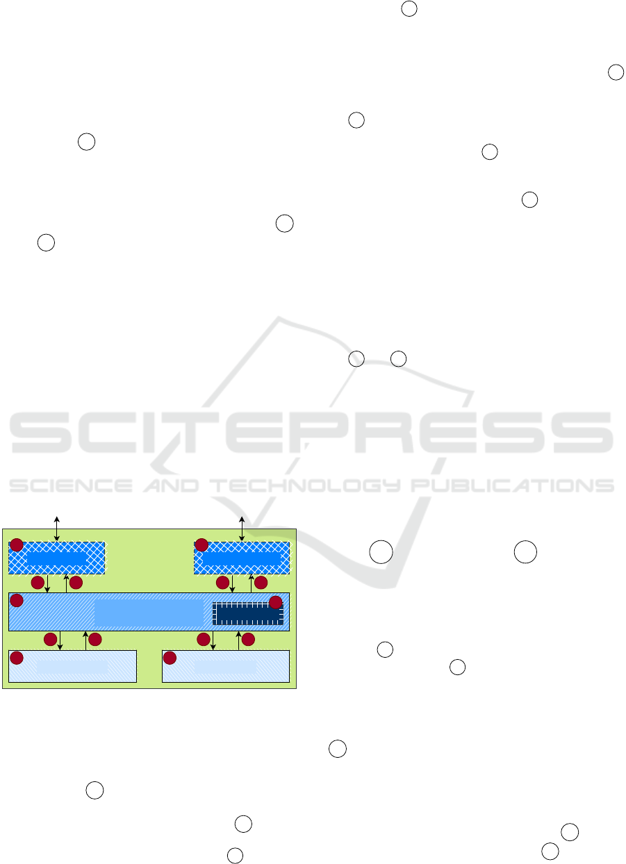
Figure 3 is a new reference architecture that en-
capsulates the main components required, as previ-
ously defined in the literature (Dalibor et al., 2022;
Kritzinger et al., 2018; Tao and Zhang, 2017). The
figure is annotated with specific “variation points”,
also known as “presence conditions” (i.e., parts that
can be enabled/disabled).
Experiment
User Agent
7A
Machine Agent
7B
Twin ObjectActual Object
1 2
5A 5B 6A 6B
8A 8B 8C 8D
Experiment Manager
(Orchestrator)
3
Workflow(s)
4
Figure 3: Generic (conceptual) Twinning Experiment archi-
tecture with presence conditions.
Following the IIRA’s functional viewpoint, func-
tional components are conceptualized in this general
architecture.
Once stage A of Figure 1 has given us a descrip-
tion of the requirements of the desired twin, one can
select an appropriate architecture in stage
B .
In Figure 3, each component has been annotated
with a number. The Actual Object (AO) 1 and Twin
Object (TO) 2 are given a behaviour via the opera-
tional semantics of the formalism in which they are
modelled (not shown). This can be a neural network,
the execution of code, observed or controlled real-
world behaviour, etc. It is important to note that 1
is an abstraction of a specific view of the actual world
(and environment) in which the AO is active.
3 is a so-called “Experiment Manager” (or “Or-
chestrator” in the case of black-box components)
which contains a workflow 4 that indicates how the
experiment is to be executed. Because the experiment
is created for a specific set of requirements, the re-
quirement’s logic is contained in 3 . For instance,
if we only want to have a dashboard to visualize the
current state, the collection of this state is done by the
Experiment Manager. If instead our goal is Anomaly
Detection, the Experiment Manager needs to compute
the distance between behaviour observed by the Ac-
tual Object and computed by the Twin Object – typ-
ically over a moving time window – and produce a
notification when this distance exceeds a given thresh-
old.
5 and 6 denote the communication between the
Experiment Manager and the AO or TO, respectively.
Note that the downward communication may be in-
terpreted in a really broad manner. It may consider
the instructions that need to be sent to the objects,
to launch or halt their individual executions. Alter-
natively, it may also send data to update the objects
(e.g., for a Digital Generator, Digital Shadow or Dig-
ital Twin (Tekinerdogan and Verdouw, 2020)). The
upward communication can be the data that the sen-
sors in this AO or TO have captured.
The Orchestrator can communicate with a User
Agent 7A or Machine Agent 7B , access points
for a user or another system to obtain information
about/from or send information to this experiment.
This communication happens through an exposed Ap-
plication Programmer’s Interface (API) of the User
Agent and Machine Agent respectively. The commu-
nication 8 between the Agents and the Orchestrator
is bidirectional when 7 can steer the twin, and one-
directional in the case of a Digital Model or a Digital
Shadow (Kritzinger et al., 2018).
Note that each component and connection may be
present/absent, depending on the results from column
A and potential additional requirements. This yields
(at a naive first glance) 2
13
= 8192 different variations
of this figure. Note that the “Workflow(s)” component
is only present if the Experiment Manager is present.
Many of these variations are useless within the con-
text of Twinning. Ideally, the results from A provide
a subset of acceptable possibilities in
B , which can
SIMULTECH 2024 - 14th International Conference on Simulation and Modeling Methodologies, Technologies and Applications
174

be further limited by custom requirements. Each of
the resulting variants should fully represent a concep-
tual architecture of the desired Twinning system.
In Figure 4, the top-level architecture for the or-
chestration of multiple twin experiments is shown. A
top-level orchestrator receives input (from top-level
User Agent(s) and/or Machine Agent(s)) and spawns
new Twinning experiments. Note that these experi-
ments can be short-running, long-running, or never-
ending. Data gathered from the experiments is stored
in the “Historian”. This is a blackboard (append-only,
to support versioning/traceability) data lake that con-
tains all historical data of all Twinning experiments.
Reasoning can be done by querying the Historian.
This in turn may spawn new Twinning experiments.
Twinning experiments may call upon the Historian
and Reasoner, via the Orchestrator.
Orchestrator
Twinning Experiments
Historian
(Storage)
Reasoner
Inferencer
User Agents
Machine Agents
Figure 4: Orchestration of the conceptual architecture;
adapted from (Paredis and Vangheluwe, 2022).
If the experiment that must be spawned was al-
ready carried out in the past, the orchestrator might
(driven by input from the “Reasoner” component)
collect the answers from the Historian instead (Mittal
et al., 2023). This is shown as an example on the time-
line in Figure 5. Some questions obtained from the
User/Machine Agent spawn “Reasoning” processes,
others launch Twinning experiments. “Experiment 1”
is a short experiment and “Experiment 2” is a never-
ending experiment that continually shares informa-
tion with the orchestrator.
Twin User/Machine Agent
Historian (blackboard storage)
Reasoning
Experiment 1
Experiment 2
Reasoning
time
Orchestrator
Figure 5: Timeline of Twinning experiments; adapted from
(Paredis and Vangheluwe, 2022).
3.3 Deployment / Implementation
Finally, in the “Deployment”, stage C , the concep-
tual architecture is realized. This is similar to the
IIRA’s implementation viewpoint.
The desired target platforms and technologies are
chosen/used to realize this twinning architecture. This
details the communication protocols, server operat-
ing system, modelling formalism (and toolbox) etc.
Hence, C answers how a twin can be constructed.
Going from the conceptual view to a fully de-
ployed system is a long process that consists of many
different sub-processes, each with their own options
(hardware, operating systems, software, program-
ming/modelling languages, . . . ).
Typically, the focus is on the technologies that are
to be used in the system, which happen either explic-
itly (by actively deciding), implicitly (due to the tech-
nologies available to the user), or subconsciously (due
to personal preferences). Independent of how they
happen, a choice needs to be made.
A specific conceptual architecture from stage B
is chosen and made concrete by explicitly defining the
exact behaviour of all components and connections
present.
Next, a choice must be made about the technology
stack for each of the components and connections.
This step will be the most cost- and labour-intensive,
depending on which technologies are chosen. The ex-
act technology choices can be heavily impacted by the
requirements from A , as well as by project budget.
In some situations, the resulting architecture may
be optimized, due to the selected technology stack.
Finally, the Twinning system can be deployed, after
which it should be validated and verified.
4 MODELLING AND
SIMULATING
ARCHITECTURES
The construction of a DT is a complex task with many
specific details and activities. We have identified a
three-stage approach to building one, but a lot of ef-
fort still goes into the calibration and validation of the
models, as well as the construction of the actual sys-
tem. Many choices have to be made throughout the
creation of the Twinning experiments, irrespective of
which workflow was used.
The selection of the right architecture and the ex-
act technologies (in stage C ) might be quite ad-hoc.
If B yielded a lot of viable alternatives, it might be
Modelling and Simulation-Based Evaluation of Twinning Architectures and Their Deployment
175

unclear which alternative architecture is the most ap-
propriate. Similarly, the choice of a certain technol-
ogy might have a large impact on the behaviour of
the overall Twinning architecure’s performance. This
will only be known upon deployment. Maybe at one
point, a user would also like to change a modelling
formalism, or a communication protocol to check its
influence on the whole system. Instead of needing to
redeploy and invest in this potential negative change,
it would be useful for the user to be able to verify this
beforehand.
Architecture space exploration and deployment
space exploration are needed, where multiple solu-
tions for all twin variants can be compared objec-
tively. Doing this using fully realized implementa-
tions can easily become prohibitively expensive.
Model-Based Systems Engineering (MBSE) is
meant to support designing (complex) CPS. Follow-
ing the MBSE paradigm, it stands to reason that we
construct a simulatable model of the system’s archi-
tecture and its deployment. We can easily modify this
architecture/deployment model to verify the influence
of changes on overall system performance.
5 PROOF-OF-CONCEPT
In order to illustrate the proposed modelling and sim-
ulation of Twinning architectures, a small example of
a ship and its 1D motion is used. Keeping the example
simple allows us to focus on the core contribution of
this work. It is meant as a proof-of-concept and does
not provide an exhaustive identification of all possible
variants.
We consider a ship that only sails in a single di-
rection (i.e., turning is not part of this example nor
are pitch and yaw taken into account). We assume
that the ship’s motion is not influenced by external
factors such as currents, wind, tides, etc. We know
the length L (21.54 m) of the ship, the estimated dry
mass m (32,000 kg), and the estimated submerged
surface area S (261 m
2
) of the vessel (based on ear-
lier parameter estimation experiments). Experiments
were carried out in water with a temperature of 15
◦
C
(which makes the density of the water ρ approxi-
mately 1025 kg/m
3
).
For the experiment described in this paper, we did
not use our real-world AO directly. Rather, a third
party provided a detailed data trace and a Functional
Mockup Unit (FMU) (MODELISAR consortium and
Modelica Association Project “FMI”, 2024), an ex-
ecutable capable of mimicking the behaviour of this
ship. The FMU is a black-box that produces mea-
sured velocity v
AO
at each point in time. As an ex-
ternal input, the ship receives a time-varying desired
target velocity v
t
. In this instance, the FMU also pro-
duces this v
t
at each point in time. This desired target
velocity will also be input to the TO.
Instead of merely constructing a simulation of this
system, we would like to construct a twin, such that
we can detect anomalies. We have done so following
the methodology presented in section 3 and Figure 1.
Focusing on the requirements A , we would like
to construct a Digital Shadow (Kritzinger et al.,
2018), a simulation (in a TO) running in parallel with
the real System under Study (in an AO) such that we
can visualize its behaviour as well as the deviations
from the expected behaviour as given by the simula-
tion in a simple dashboard. If anomalies –significant
deviations of the actual behaviour from the simulated
behaviour– occur, we would like to be notified in the
dashboard.
From our large goal feature tree (Figure 2), we se-
lect the requirements that are necessary for this use-
case. A subset of these are summarized in table 1. In
the table, PLM means Product Life-cycle Modelling.
Table 1: Selected Requirements for the ship example.
Dimension Requirement
Twin Type Digital Shadow
PLM Stage As-Operated
Operation Data Allocation
Monitoring
Visualization Animation
Timing Real-Time
Execution Live
Quality Assurance Consistency
Ilities Reliability
Reuse Reproducibility
Safety Legal Safety
Physical Laws
Human Safety
In terms of operation for this Digital Shadow, we
would like to monitor the current (and past) states,
supporting data allocation. This way we can visual-
ize a (historical) plot of the system state, which is an-
imated during a real-time, live execution. When look-
ing at this plot, a human may assess the consistency
and reliability of the constructed twin. Furthermore
we can observe whether (1) the velocity of the ship
stays within legal bounds (legal safety), (2) the ship’s
engine can produce enough torque to reach the de-
sired velocities (physical laws), and (3) passengers do
not fall due to excessive acceleration or deceleration
(human safety). Finally, we may want to reproduce
such an experiment, also for different ships.
SIMULTECH 2024 - 14th International Conference on Simulation and Modeling Methodologies, Technologies and Applications
176
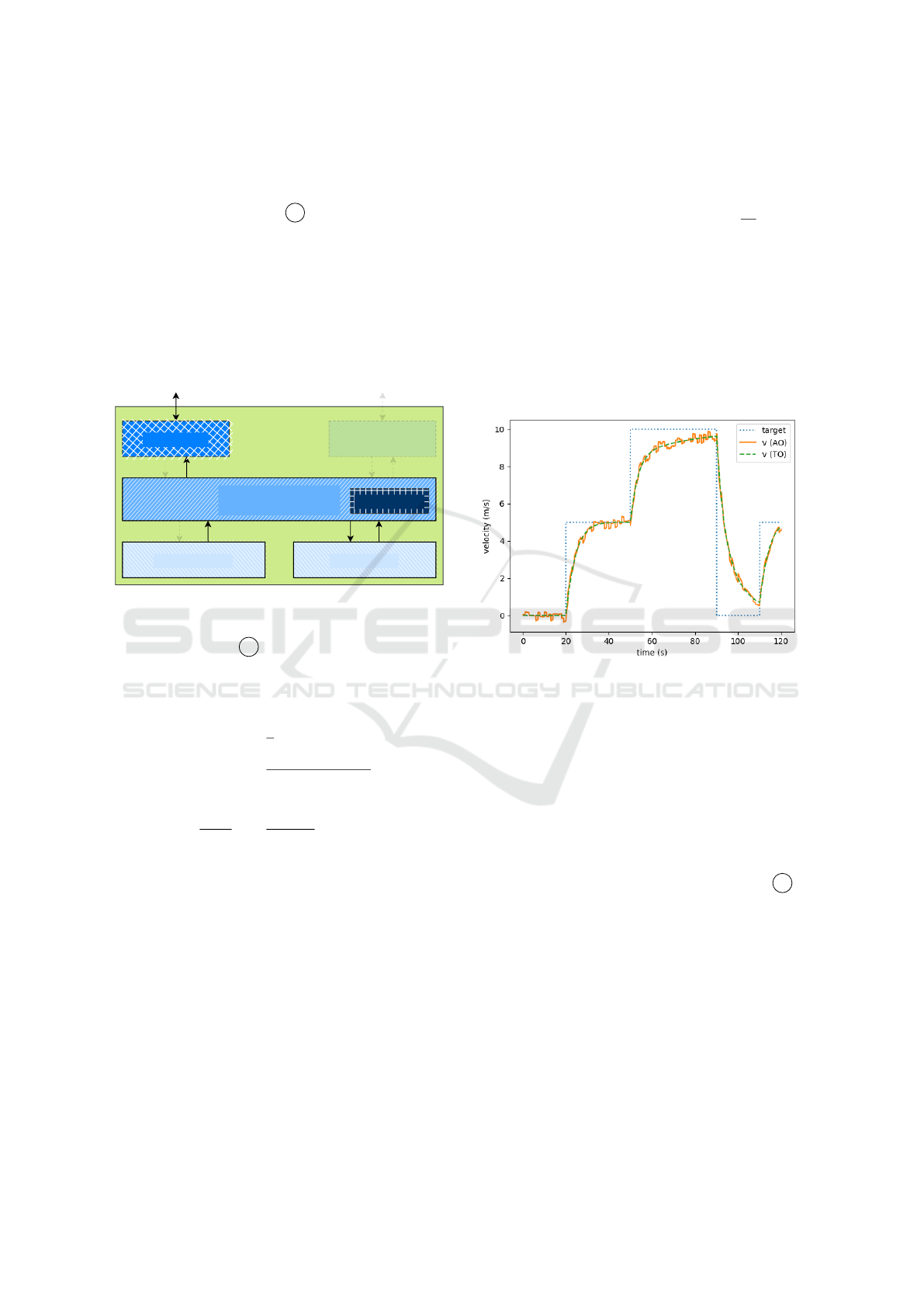
The above helped us identify which components
are required (and which can be omitted) in the con-
ceptual reference architecture presented earlier in Fig-
ure 3. This is done in stage B .
The black-box model is the AO and our ideal
model is simulated in the TO. The AO cannot be con-
trolled, but does provide information (i.e., the v
t
) to
the TO. A co-simulation orchestrator, interleaving the
time-stepping of the AO and TO, is required for cor-
rect results. A Machine Agent is not needed, but a
simple visualization dashboard is required in the User
Agent. These considerations result in the architectural
variant shown in Figure 6.
Experiment
User Agent
Machine Agent
Twin ObjectActual Object
Experiment Manager
(Orchestrator)
Workflow(s)
Figure 6: Conceptual architecture variant for the ship use-
case.
Moving to stage C , we can start concretizing this
system. In the TO, we use a simple model for physical
plant and controller. The plant model consists of the
following Ordinary Differential Equation (ODE):
F
R
=
1
2
· ρ · v
2
TO
· S ·C
f
C
f
=
0.075
(log
10
(Re) − 2)
2
Re = v
TO
· L/k
dv
TO
dt
=
F
T
− F
R
m
(1)
F
R
is the resistive force the ship experiences when
sailing at velocity v. ρ, S, L and C
f
were introduced
earlier. Re is the Reynolds number for the ship in wa-
ter which indicates the nature (laminar or turbulent) of
the fluid flow. k is the dynamic viscosity of the water
(1.188· 10
−6
kg/(m · s)). F
T
is the traction force. This
traction force is determined by a PID controller which
minimizes the difference between the actual velocity
v
TO
and the desired (or target) velocity v
t
. The tar-
get velocity profile is an external input to the system
which in this case is produced by the AO. Our PID
controller mimics the controller implemented in the
real-world System under Study. The PID controller is
characterized by proportional, integral and derivative
parameters K
p
, K
i
, and K
d
.
e = v
TO
− v
t
F
T
= K
p
· e + K
i
·
R
e dt + K
d
·
de
dt
(2)
We have modelled the controller equations combined
with the plant equations in Modelica. OpenModelica
was used to generate an FMU simulation unit.
In an ideal scenario, the plot shown in Figure 7
should be obtained. It shows the velocity of the real
ship v
AO
(full orange line) and that of its twin v
TO
(dashed green line) as they try to reach the varying
target velocity v
t
(dotted blue line), as they are dis-
played in the dashboard.
Figure 7: Velocity of the real ship (AO) versus that of its
twin (TO) as they try to reach the varying target velocity v
t
.
From the plot, it is clear that, as was to be ex-
pected, v
AO
contains sensor noise. The behaviour
seems normal however. If some event were to prevent
the velocity of the ship to change as expected, such as
being stuck on a sand bank, or the engine failing, this
anomaly can easily be identified in the dashboard.
5.1 DEVS Model
Note that we have not fully completed column C as
we did not discuss actual deployment. Suppose that
we don’t know which communication protocol to use
in order to get the results of Figure 7. Instead of test-
ing the system with a large number of technologies,
we propose to use MBSE techniques to explore the
deployment space. Different deployment architecture
will be simulated. As we are simulating Twinning ar-
chitectures, these will themselves include simulations
(of the ship in this case).
According to MPM principles, we we need to se-
lect a “most appropriate” formalism to model the ar-
chitecture. (Vangheluwe, 2000) shows that the DEVS
can be used as a modular assembly language to which
Modelling and Simulation-Based Evaluation of Twinning Architectures and Their Deployment
177

a plethora of other existing languages can be mapped,
preserving behaviour. Given the heterogeneity of
Twinning architectures, and as open modelling and
simulation tooling exist, DEVS seems the most ap-
propriate formalism to date.
Hence, DEVS will be used to simulate the exact
architecture, using specific technologies. For sim-
plicity, an “FMURunner” atomic component is con-
structed that can simulate a given FMU for a single
time-step (upon receiving an input). The orchestrator
can then easily co-simulate AO and TO. The Python-
PDEVS code for the orchestrator is shown in Figure 8.
1 c l a ss Or c h e st r at o r ( At om i c D EV S ) :
2 def __ i n i t __ ( self , n a me , s t e p si ze = 0 .1 , st o p ti me = 1 . 0) :
3 su pe r () . _ _ i ni t_ _ ( na m e )
4 se l f . s te ps i ze , s el f . s t o p t i me = st ep s iz e , sto pt i m e
5 se l f . mo du le s = [" A O " , " T O " ]
6 se l f . s t a te = {
7 " d a ta " : { m :[] fo r m in s e lf . m od ul es } ,
8 " c ur re n t " : 0, " m us t _ o ut p u t " : T r ue ,
9 " t i me " : { m: 0 . 0 f o r m in s e lf . m od ul e s }
10 }
11 se l f . in p u ts = { m: s e lf . a d d I n P or t ( " % s - da ta " % m)
for m in se lf . m o d ul es }
12 se l f . ou tp ut s = { m: se lf . a dd O u t Po r t ( " % s - a c t i o n " % m
) for m in se lf . m od ul es }
13
14 def get _c u r ( s el f ) :
15 re tu rn sel f . m od u l e s [ s el f . s ta t e [ " cu rr en t " ] ]
16
17 def ti m e A d v an c e ( s el f ) :
18 if se lf . st at e [ " m u st _ o u tp u t " ]:
19 r et u r n 0 .0
20 re tu rn IN F I NI TY
21
22 def ex tT r a n s i t io n ( self , in p u t s ) :
23 if se lf . in p u t s [ s e lf . g et _c ur () ] i n inp ut s :
24 c u r = se lf . g e t _ c u r ()
25 d at a = inp u t s [ s el f . i np ut s [ c ur ]] [0 ]
26 if ro un d ( dat a [0] - s el f . s ta t e [ " t im e " ][ cu r ] , 6 ) >=
se l f . st e p s i z e :
27 se l f . st a t e [ " c ur re nt " ] = ( se lf . st at e [ " c u r r e n t " ]
+ 1) % len ( se l f . mo du le s )
28 s el f . s ta t e [ " mu s t_ o u t pu t " ] = Tr ue
29 s el f . s ta t e [ " t im e " ][ cu r ] = dat a [ 0 ]
30 s el f . s ta t e [ " d at a " ][ cu r ]. a p p e n d ( d ata )
31 re tu rn sel f . s ta t e
32
33 def ou t p ut Fn c ( se lf ) :
34 if se lf . g e t _ c ur () == se lf . m od ul es [ 0] :
35 r et u r n {
36 se l f . ou tp ut s [ se l f . mo du l e s [ 0 ] ] : [ " d oS te p " ]
37 }
38 el i f s el f . g e t _ cu r ( ) == s el f . m o d u l e s [1 ] :
39 las t , pr ev = Non e , No ne
40 f o r tim e , v a l u e i n self . s t a t e [ " d at a " ][ se lf .
mo du le s [ 0 ]] :
41 if ti me = = s e lf . s t a t e [ " t im e " ][ se l f . ge t _ c u r () ] :
42 la s t = time , va l u e
43 br ea k
44 el i f t im e > se lf . st at e [ " t i me " ][ s el f . ge t_ cu r () ]:
45 la s t = time , va l u e
46 if pr ev i s no t N o ne :
47 la s t = l e rp ( prev , la s t , t i me )
48 br ea k
49 pr e v = time , va l u e
50
51 r et u r n {
52 se l f . ou tp ut s [ se l f . mo du l e s [ 1 ] ] : [ l as t ]
53 }
54 re tu rn {}
55
56 def in tT r a n s i t io n ( se lf ) :
57 se l f . s t a te [ " m us t _ o u t p ut " ] = Fal se
58 re tu rn sel f . s ta t e
Figure 8: Orchestrator in PythonPDEVS.
DEVS performance models exist for specific com-
munication protocols and technologies (Burger et al.,
2019; Maruyama et al., 2016). However, in many
situations this may not be the case. For those in-
stances, we do have access to the exact technologies
themselves. We manipulate the DEVS components to
make use of the actual technologies, instead of them
being an abstraction thereof. This ensures the usage
of the actual system components, including their hid-
den complexities and unknown influences to the envi-
ronment. This makes later conversion of the simula-
tion into a realization easier. A similar approach was
used in (Denil et al., 2017) to explore design and de-
ployment alternatives for a car power window. (Syr-
iani and Vangheluwe, 2013) applied this approach
to evaluate implementations of graph transformation
schedules.
We know that a communication protocol intro-
duces network delays, but does not alter the data that
is transferred. Running multiple experiments with the
actual system in place will allow us to construct a dis-
tribution for the expected time delays, which can sub-
sequently be used in a pure simulation context.
5.2 Analysis of Alternatives
Before actually building a working DEVS model of
the presented architecture, it is imperative that the
conceptual architecture is concretized. But, to do so,
we would need to know some additional information
about the components. For instance, which communi-
cation protocol, such as polling or publish-subscribe,
best fits our needs. Or, alternatively, when a commu-
nication protocol is chosen, which technology is most
appropriate?
When experimenting with different technologies,
we use the traces in Figure 7 to verify correct be-
haviour.
5.2.1 Different Communication Protocol Tests
We would like the Digital Shadow to work online,
such that we can detect anomalies in the ship’s ve-
locity as soon as they occur. This implies a commu-
nication protocol that is able to process information
as-fast-as-possible, with minimal network delays.
As an example, we will compare a publish-
subscribe setup, using MQTT (https://mqtt.org/),
with a polling setup, using OPC UA (https://
opcfoundation.org/about/opc-technologies/opc-ua/),
running on top of TCP/IP. A shared memory imple-
mentation is used as a baseline implementation. In
Figure 9, a deployment diagram for the MQTT setup
is shown. Other deployment diagrams are omitted
due to space constraints.
SIMULTECH 2024 - 14th International Conference on Simulation and Modeling Methodologies, Technologies and Applications
178
Windows 10
Python 3.11
FMPy
Paho-MQTT
Actual Object
FMU
MQTT Client
Mosquitto
(MQTT Message Broker)
Python 3.11
FMPy
Paho-MQTT
Twin Object
FMU
MQTT Client
Figure 9: Deployment Diagram for MQTT experiment
setup.
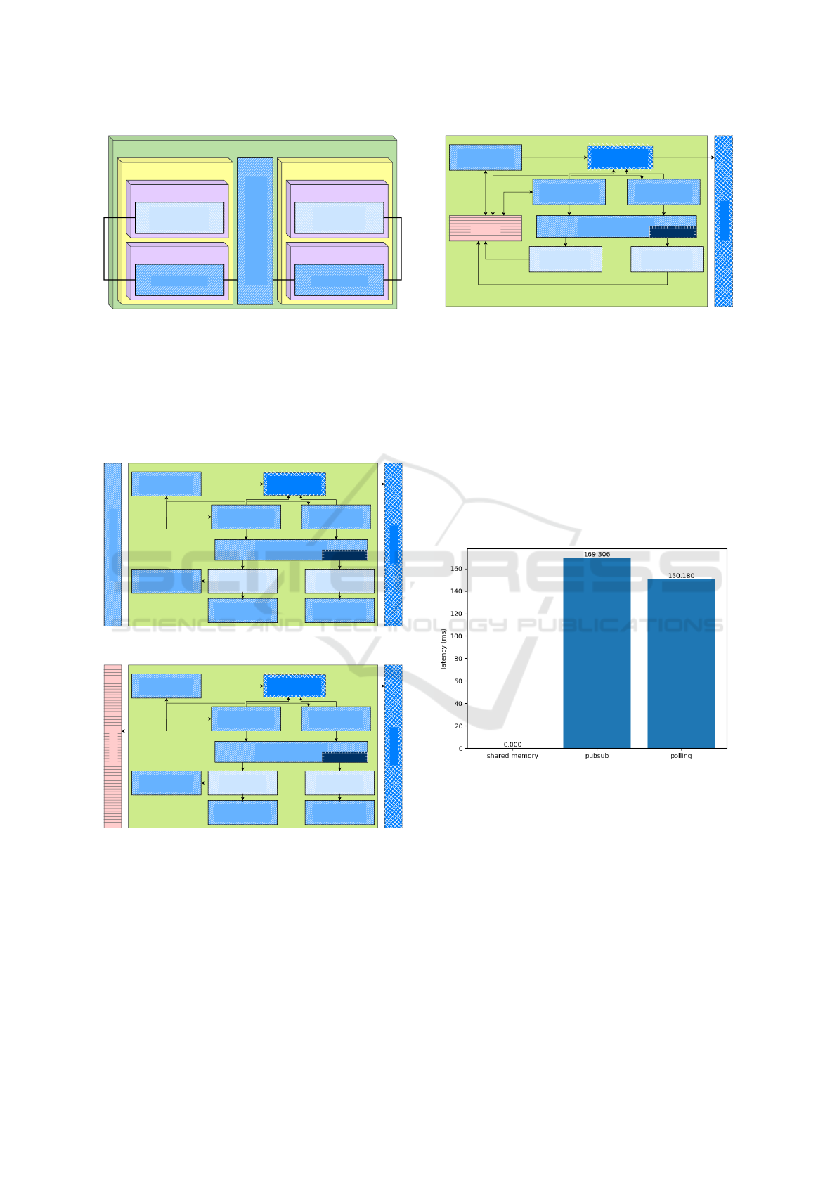
For each of the alternatives, a DEVS simulation
model of the deployed architecture is constructed and
evaluated. Figure 10 shows the publish-subscribe al-
ternative, Figure 11 the polling alternative, and Fig-
ure 12 the shared memory alternative DEVS coupled
model.
Experiment (PubSub)
Actual Object
(FMURunner)
Publisher
channel: "target"
Publisher
channel: "AO/v"
Twin Object
(FMURunner)
Publisher
channel: "TO/v"
instruct target
Subscriber
channel: "target"
Subscriber
channel: "AO/v"
Subscriber
channel: "TO/v"
AO TO
User Agent
(Data Collector)
Experiment Manager
(Orchestrator)
Subscription Handler
Dashboard
Workflow(s)
Figure 10: Publish Subscribe DEVS model (MQTT).
Experiment (Polling)
Actual Object
(FMURunner)
Publisher
channel: "target"
Publisher
channel: "AO/v"
Twin Object
(FMURunner)
Publisher
channel: "TO/v"
instruct target
Poller
channel: "target"
Poller
channel: "AO/v"
Poller
channel: "TO/v"
AO TO
User Agent
(Data Collector)
Experiment Manager
(Orchestrator)
Data Lake
Dashboard
Workflow(s)
Figure 11: Polling DEVS model (OPC UA on top of
TCP/IP).
The “Dashboard” is a process that introspects the
state of the “Data Collector” and plots the data every
x time.
In Figure 12, the “Requester”s send a request mes-
sage to access a variable in the “Memory” component.
The latest value of the variable will be returned. In
Figure 10, the “Publisher”s publish data on a commu-
nication channel and a “Subscription Handler” pro-
Experiment (Shared Memory)
target
AO/v
Actual Object
(FMURunner)
TO/v
Twin Object
(FMURunner)
instruct target
Requester
variable: "target"
Requester
variable: "AO/v"
Requester
variable: "TO/v"
AO TO
User Agent
(Data Collector)
Experiment Manager
(Orchestrator)
Dashboard
Memory
Workflow(s)
Figure 12: Shared Memory DEVS model.
cess applies a real-time interrupt in the “Subscriber”s
of the same channel(s). Figure 11 is similar, but com-
bines the variable request from Figure 12 and the ex-
ternal process from Figure 10.
Notice that we chose to let the orchestrator com-
municate directly with both AO and TO. An alterna-
tive would be to let this communication also happen
via a resource-constrained communication channel.
Figure 13 shows a bar plot of the latency perfor-
mance metric obtained after running the three differ-
ent Twinning experiments on the same system, using
the different communication technologies.
Figure 13: Average latency of different communication pro-
tocols.
As can be seen, using shared memory will be the
most efficient approach, followed by polling. Publish-
subscribe is the slowest of the three.
5.2.2 Different Publish-Subscribe
Implementations
We will now compare multiple publish-subscribe al-
ternatives. Note that this is by no means a general
analysis of these technologies, but rather a use-case-
specific comparison on which one works the best in
this case.
Multiple technologies are used in industry. We
Modelling and Simulation-Based Evaluation of Twinning Architectures and Their Deployment
179

compare the latency of ROS2 (https://www.ros.org/),
MQTT, and OPC UA’s publish-subscribe system (run-
ning on top of TCP/IP). All these technologies will
use Figure 10 as a concrete system architecture.
Figure 14 shows a bar plot of the latency obtained
after running the publish-subscribe experiments on
the same system, using the different technologies.
Figure 14: Average latency of different publish-subscribe
technologies.
Out of the three options, MQTT is the best, fol-
lowed by ROS2 and OPC UA respectively. All three
options yield latencies below 1 second, making them
all acceptable for this specific scenario.
6 RELATED WORK
Ever since the conceptualization of Digital Twins
(DTs) (Grieves and Vickers, 2017) and its intro-
duction to Industry 4.0 (Boss et al., 2020), a
plethora of (reference) architectures have been pro-
posed (Kritzinger et al., 2018; Tao and Zhang, 2017;
Llopis et al., 2023). Yet, most of these architectures
either remain conceptual, or too abstract to translate
into a working Twinning system or are rather ad hoc
(AboElHassan et al., 2023). They also often omit cru-
cial information about the nature of the twinning ac-
tivities (Oakes et al., 2021), resulting in a lack of con-
sensus (B
´
echu et al., 2022).
Unification of Twinning architectures is a perti-
nent topic in the literature, with many studies trying
to find common DT “requirements” (Dalibor et al.,
2022; Van der Valk et al., 2020; Jones et al., 2020).
The Asset Administration Shell (AAS) (Boss
et al., 2020) provides a methodology for capturing
the essential information related to assets (including
by means of twins), by means of the IIRA (Industry
IoT Consortium, 2022).
(Oakes et al., 2021) identify 14 characteristics for
experience report authors to better describe the capa-
bilities of their twins. Additionally, the relationship
to the AAS is described. (Ferko et al., 2024) provide
a mapping from architectural models in SysML onto
the AAS.
For behavioural simulation of architecture mod-
els to support quantitative analysis and compari-
son of alternatives, the DEVS formalism is a com-
mon choice (Vangheluwe, 2000). (Ahmad and Sar-
joughian, 2023) focus on the translation between
AADL and DEVS and (Kapos et al., 2014) does the
same for SysML. (Denil et al., 2017) did this for the
deployment variants of a power window and (Syriani
and Vangheluwe, 2013) used a similar approach to ex-
plore model transformation schedules. In the health-
care domain, discrete-event simulation is a common
approach to performance analysis (G
¨
unal and Pidd,
2010).
7 CONCLUSIONS AND FUTURE
WORK
The Twinning paradigm is increasingly seen as a so-
lution enabler for a host of problems in engineering
and science. The variety of problems leads to many
different solutions. To tackle this variability, this pa-
per proposes a three-stage workflow. In each stage,
variability may appear and choices have to be made
by the Twinning system designer.
Typically, deployment has the largest impact on
the cost for constructing a twin. As its main contribu-
tion, this paper proposes a MBSE approach to deploy-
ment space exploration. In particular, architectural
and technological alternatives are explicitly modelled
using the DEVS formalism. Simulation of these mod-
els allows for quantitative evaluation and comparison
of these alternatives. An example is the choice be-
tween ROS2 and MQTT for communication between
components. The simulation model may even be used
as a basis for the ultimate realization of the Twinning
system.
This paper uses the 1D motion of a ship as a sim-
ple example. For this example, we have analyzed
two different alternatives. This was used to demon-
strate how MBSE, and in particular, simulation-based
performance analysis can be applied to the design of
Twinning architectures.
We plan to apply the presented methodology
to different application domains we have experi-
ence with: robotics, harbour traffic, production pro-
cesses and waste water treatment. Furthermore, we
are currently exploring Twinning ecosystems. In
such ecosystems, different Twinning architectures are
SIMULTECH 2024 - 14th International Conference on Simulation and Modeling Methodologies, Technologies and Applications
180

combined. These architectures may differ in goals
and Properties of Interest, in level of abstraction or
detail, or may have been constructed for components
in a System under Study architecture (and we want a
twin of the overall SuS). Finally, we plan to inves-
tigate the relationship between the many Twinning
architectures presented in the literature and our pro-
posed workflow and reference architecture.
ACKNOWLEDGMENTS
The authors would like to thank the reviewers for their
detailed feedback and insightful comments.
This research was partially supported by Flanders
Make, the strategic research center for the manufac-
turing industry. Additionally, we would like to thank
the Port of Antwerp-Bruges for their explanations of
the nautical chain, within the context of the COOCK
project “Smart Port 2025: improving and accelerat-
ing the operational efficiency of a harbour eco-system
through the application of intelligent technologies”.
REFERENCES
AboElHassan, A., Sakr, A. H., and Yacout, S. (2023).
General purpose digital twin framework using digital
shadow and distributed system concepts. Computers
& Industrial Engineering, 183:109534.
Ahmad, E. and Sarjoughian, H. S. (2023). An Envi-
ronment for Developing Simulatable AADL-DEVS
Models. Simulation Modelling Practice and Theory,
123:102690.
B
´
echu, G., Beugnard, A., Cao, C. G. L., Perez, Q., Urtado,
C., and Vauttier, S. (2022). A software engineering
point of view on digital twin architecture. 2022 IEEE
27th International Conference on Emerging Technolo-
gies and Factory Automation (ETFA), pages 1–4.
Boss, B., Malakuti, S., Lin, S. W., Usl
¨
ander, T., Clauer, E.,
Hoffmeister, M., and Stojanovic, L. (2020). Digital
twin and asset administration shell concepts and ap-
plication in the industrial internet and industrie 4.0.
Industrial Internet Consortium: Boston, MA, USA.
Burger, A., Koziolek, H., R
¨
uckert, J., Platenius-Mohr, M.,
and Stomberg, G. (2019). Bottleneck identification
and performance modeling of OPC UA communica-
tion models. In Proceedings of the 2019 ACM/SPEC
International Conference on Performance Engineer-
ing, pages 231–242.
Dalibor, M., Jansen, N., Rumpe, B., Schmalzing, D.,
Wachtmeister, L., Wimmer, M., and Wortmann, A.
(2022). A Cross-Domain Systematic Mapping Study
on Software Engineering for Digital Twins. Journal
of Systems and Software, 193:111361.
de Weck, O. L., Roos, D., Magee, C. L., and Vest, C. M.
(2011). Life-Cycle Properties of Engineering Sys-
tems: The Ilities. In Engineering Systems: Meet-
ing Human Needs in a Complex Technological World,
pages 65–96. MIT Press.
Denil, J., Meulenaere, P. D., Demeyer, S., and Vangheluwe,
H. (2017). DEVS for AUTOSAR-based system de-
ployment modeling and simulation. SIMULATION,
93(6):489–513.
Ferko, E., Berardinelli, L., Bucaioni, A., Behnam, M., and
Wimmer, M. (2024). Towards Interoperable Digital
Twins: Integrating SysML into AAS with Higher-
Order Transformations. In 3rd International Work-
shop on Digital Twin Architecture (TwinArch) and
Digital Twin Engineering (DTE).
Grieves, M. (2014). Digital twin: manufacturing excel-
lence through virtual factory replication. White paper,
1(2014):1–7.
Grieves, M. and Vickers, J. (2017). Digital twin: Mitigat-
ing unpredictable, undesirable emergent behavior in
complex systems. In Transdisciplinary perspectives
on complex systems, pages 85–113. Springer.
G
¨
unal, M. M. and Pidd, M. (2010). Discrete event simu-
lation for performance modelling in health care: a re-
view of the literature. Journal of Simulation, 4:42–51.
Industry IoT Consortium (2022). The Industrial Internet
Reference Architecture. Accessed: April 5th 2024.
Jones, D., Snider, C., Nassehi, A., Yon, J., and Hicks, B.
(2020). Characterising the Digital Twin: A system-
atic literature review. CIRP Journal of Manufacturing
Science and Technology, 29:36–52.
Kang, K. C., Cohen, S. G., Hess, J. A., Novak, W. E.,
and Peterson, A. S. (1990). Feature-oriented domain
analysis (FODA) feasibility study. Technical report,
Carnegie Mellon University.
Kang, K. C. and Lee, H. (2013). Variability modeling. In
Systems and software variability management, pages
25–42. Springer.
Kapos, G.-D., Dalakas, V., Nikolaidou, M., and Anag-
nostopoulos, D. (2014). An Integrated Framework
for Automated Simulation of SysML Models Using
DEVS. Simulation, 90(6):717–744.
Kritzinger, W., Karner, M., Traar, G., Henjes, J., and Sihn,
W. (2018). Digital Twin in Manufacturing: A Cate-
gorical Literature Review and Classification. IFAC-
PapersOnLine, 51(11):1016–1022.
Llopis, J., Criado, J., Iribarne, L., Munoz, P., Troya, J., and
Vallecillo, A. (2023). Modeling and Synchronizing
Digital Twin Environments. In 2023 Annual Mod-
eling and Simulation Conference (ANNSIM), pages
245–257, Los Alamitos, CA, USA. IEEE Computer
Society.
Madni, A. M., Madni, C. C., and Lucero, S. D. (2019).
Leveraging digital twin technology in model-based
systems engineering. Systems, 7(1):7.
Maruyama, Y., Kato, S., and Azumi, T. (2016). Explor-
ing the performance of ROS2. In Proceedings of the
13th international conference on embedded software,
pages 1–10.
Minerva, R., Lee, G. M., and Crespi, N. (2020). Digital
Twin in the IoT Context: A Survey on Technical Fea-
Modelling and Simulation-Based Evaluation of Twinning Architectures and Their Deployment
181

tures, Scenarios, and Architectural Models. Proceed-
ings of the IEEE, 108(10):1785–1824.
Mittal, R., Eslampanah, R., Lima, L., Vangheluwe, H., and
Blouin, D. (2023). Towards an Ontological Frame-
work for Validity Frames. In 2023 ACM/IEEE In-
ternational Conference on Model Driven Engineer-
ing Languages and Systems Companion (MODELS-
C), pages 801–805. IEEE.
MODELISAR consortium and Modelica Association
Project “FMI” (2024). Functional mockup interface
standard 3.0. https://fmi-standard.org/docs/3.0/.
Mosterman, P. J. and Vangheluwe, H. (2004). Computer au-
tomated multi-paradigm modeling: An introduction.
Simulation, 80(9):433–450.
Oakes, B. J., Parsai, A., Meyers, B., David, I., Mierlo,
S. V., Demeyer, S., Denil, J., Meulenaere, P. D., and
Vangheluwe, H. (2021). A digital twin description
framework and its mapping to asset administration
shell. In Companion Proceedings of the International
Conference on Model-Driven Engineering and Soft-
ware Development, pages 1–24. Springer.
Paredis, R., Gomes, C., and Vangheluwe, H. (2021). To-
wards a Family of Digital Model / Shadow / Twin
Workflows and Architectures. In Proceedings of
the 2nd International Conference on Innovative In-
telligent Industrial Production and Logistics (IN4PL
2021), pages 174–182. SCITEPRESS – Science and
Technology Publications, Lda.
Paredis, R. and Vangheluwe, H. (2022). Towards a Dig-
ital Z Framework Based on a Family of Architec-
tures and a Virtual Knowledge Graph. In Compan-
ion Proceedings of the 25th International Conference
on Model Driven Engineering Languages and Systems
(MODELS-C).
Paredis, R., Vangheluwe, H., and Albertins, P. A. R. (2024).
COOCK project Smart Port 2025 D3.1: “To Twin
Or Not To Twin”. Technical report, University of
Antwerp. ArXiv preprint.
Plesser, H. E. (2018). Reproducibility Vs. Replicability: A
Brief History Of A Confused Terminology. Frontiers
in neuroinformatics, 11:76.
Qamar, A. and Paredis, C. (2012). Dependency Modeling
And Model Management In Mechatronic Design. In
Proceedings of the ASME Design Engineering Tech-
nical Conference, volume 2, Chicago, IL, USA.
SEBoK Editorial Board (2023). The Guide to the Systems
Engineering Body of Knowledge (SEBoK). Accessed:
11th of April 2024.
Singh, R. (1996). International Standard ISO/IEC 12207
software life cycle processes. Software Process Im-
provement and Practice, 2(1):35–50.
Syriani, E. and Vangheluwe, H. (2013). A modular timed
graph transformation language for simulation-based
design. Software & Systems Modeling, 12:387–414.
Tao, F. and Zhang, M. (2017). Digital twin shop-floor: a
new shop-floor paradigm towards smart manufactur-
ing. IEEE Access, 5:20418–20427.
Tekinerdogan, B. and Verdouw, C. (2020). Systems archi-
tecture design pattern catalog for developing digital
twins. Sensors, 20(18):5103.
Van Acker, B., Meulenaere, P. D., Vangheluwe, H., and De-
nil, J. (2024). Validity frame–enabled model-based
engineering processes. Simulation, 100(2):185–226.
Van der Valk, H., Haße, H., M
¨
oller, F., Arbter, M., Hen-
ning, J.-L., and Otto, B. (2020). A taxonomy of digital
twins. In AMCIS, pages 1–10, Salt Lake City, USA.
Vangheluwe, H. (2000). DEVS as a Common Denomina-
tor for Multi-Formalism Hybrid Systems Modelling.
In IEEE International Symposium on Computer-Aided
Control System Design, pages 129–134, Anchorage,
AK, USA.
Wanasinghe, T. R., Wroblewski, L., Petersen, B. K., Go-
sine, R. G., James, L. A., De Silva, O., Mann, G. K.,
and Warrian, P. J. (2020). Digital twin for the oil and
gas industry: Overview, research trends, opportuni-
ties, and challenges. IEEE access, 8:104175–104197.
Zeigler, B. P. (1984). Multifacetted Modelling and Discrete
Event Simulation. Academic Press, London.
Zeigler, B. P., Muzy, A., and Kofman, E. (2018). Theory
of Modeling and Simulation. Academic Press, New
York, 3rd edition.
SIMULTECH 2024 - 14th International Conference on Simulation and Modeling Methodologies, Technologies and Applications
182
