
Efficient Modelling with Logic-Labelled Finite-State Machines of
IEC 61499 Function Blocks: Simulation, Execution and Verification
Vladimir Estivill-Castro
1 a
, Miguel Carrillo
2 b
and David A. Rosenblueth
2 c
1
Department of Engineering, Pompeu Fabra University, Roc Boronat 138, Barcelona 08018, Spain
2
Instituto de Investigaciones en Matem
´
aaticas Aplicadas y en Sistemas, Universidad Nacional Aut
´
onoma de M
´
exico,
Apdo. 20-126, Ciudad de M
˙
exico 01000, Mexico
Keywords:
Models of Behaviour, Finite-State Machines, Distributed Systems, Formal Verification.
Abstract:
As automation grows, so does the complexity of software systems. Hence, the urgent and pressing need
for software verification, particularly for distributed systems, as they are notoriously difficult to verify. The
widespread of verification techniques, such as model checking, however, have been hindered by requiring a
significant level of expertise. In the realm of industrial automation, on the other hand, the IEC 61499 function
block architecture has gained prominence for modelling intricate distributed automation systems, especially in
demanding scenarios such as process control. However, it suffers from being event-driven, forcing semantic
interpretations and the use of timed events by a central clock, to produce input for model checkers. We argue
that this situation can be remedied by logic-labelled finite-state machines and control-status messages. This is
the first time that these concepts have been used for producing executable and verifiable models of distributed
systems for industrial automation with communication delays as is the current environment of application of
the IEC 61499.
1 INTRODUCTION
“Formal methods are critical to the development of
autonomous systems. Moreover, verification of the be-
haviour of autonomous systems is especially impor-
tant when they are embedded in safety-critical sys-
tems, which are increasingly being introduced into ev-
eryday settings.” (Provan, 2024). For effective appli-
cation (Sinha et al., 2019), formal verification neces-
sitates the development of tools and methods seam-
lessly integrating design models with their simulation,
execution, and formal verification of models without
semantic discrepancies. We introduce logic-labelled
finite-state machines (LLFSMs) for modelling dis-
tributed systems described with the IEC 61499 stan-
dard and show that this enables the simulation, execu-
tion, and formal verification of design. We illustrate
our approach with a three-level elevator.
In the realm of industrial automation, the
IEC 61499 standard’s function block architec-
ture (Vyatkin, 2011) is gaining prominence for mod-
elling intricate distributed automation systems, par-
a
https://orcid.org/0000-0001-7775-0780
b
https://orcid.org/0000-0003-2105-3075
c
https://orcid.org/0000-0001-8933-8267
ticularly in demanding scenarios such as process con-
trol. A factor fuelling this explosion of the IEC 61499
standard is the integration of operational technology
(OT) with information technology (IT), resulting in a
critical shift in the industrial sector (Bencherki et al.,
2024). (Bencherki et al., 2024) believes that Infor-
mation Technology’s rapid advancements have out-
paced those in OT. As a result, the IEC 61499 stan-
dard has been postulated as the most suitable tool for
the integration of IT and OT in industrial automa-
tion (Bencherki et al., 2024).
Like Ptolemy II, IEC 61499 uses event-driven
block diagrams for modelling cyber-physical systems
(CPSs), integrating physical processes with control
and communication mechanisms. While simulation
is the most commonly used validation method, it
has limitations in identifying potential faults. Model
checking provides exhaustive testing but faces risks,
such as combinatorial explosion, particularly with
complex data types and computations.
(Sinha et al., 2019) reviewed the application of
formal methods in the context of industrial automa-
tion. Over the past 15 years of research, some ad-
vancements have been made in formal modelling
within the IEC 61499 framework, though early efforts
Estivill-Castro, V., Carrillo, M. and Rosenblueth, D. A.
Efficient Modelling with Logic-Labelled Finite-State Machines of IEC 61499 Function Blocks: Simulation, Execution and Verification.
DOI: 10.5220/0013095200003896
In Proceedings of the 13th International Conference on Model-Based Software and Systems Engineering (MODELSWARD 2025), pages 141-149
ISBN: 978-989-758-729-0; ISSN: 2184-4348
Copyright © 2025 by Paper published under CC license (CC BY-NC-ND 4.0)
141

were limited by support for only basic data types,
non-timed semantics, and small-scale systems.
One of the most serious limitations was the
definition of a semantics for the IEC 61499. In
2010, (Cengic and Akesson, 2010) highlighted that
“IEC 61499 is based on function blocks for devel-
oping distributed control applications. However, the
standard has no formal semantics, and different in-
terpretations of it have emerged. Since then, many
efforts have been dedicated to providing such seman-
tics (Vyatkin, 2009; Lindgren et al., 2015; Pang et al.,
2014; Dubinin and Vyatkin, 2012).
We use LLFSMs (Carrillo et al., 2020) and
control-status messages (Kopetz, 2011) to demon-
strate that we can efficiently and effectively produce
models for industrial automation analogous to those
of the function blocks of the IEC 61499 architecture.
In Section 2, we review related work. In Section 3,
we show the modelling of a canonical example of the
IEC 61499 architecture. Subsection 3.1 describes the
case study appears repeatedly in the literature (Droz-
dov et al., 2021; Shatrov and Vyatkin, 2021; Droz-
dov et al., 2017) of formal verification of a complex
distributed system of function blocks with communi-
cation delays on messages. Subsection 3.2 presents
the model when there are no delays in the commu-
nication channels. In this case, a simple controller
results in an executable and verifiable model that sat-
isfies safety properties and liveness properties. How-
ever, in Subsection 3.3, we do model the delays in
the communication channel and show that the sim-
ple controller is insufficient. All safety properties and
liveness properties become false. Thus, in Subsec-
tion 3.4 we introduce the corrected controller that ac-
counts for message delays, and all properties become
valid again. Section 3.6 shows that our modelling en-
ables more efficient formal verification than an ear-
lier version available in GitHub (Shatrov, 2021). Sec-
tion 4 provides conclusions.
2 RELATED WORK
A function block is the modelling unit of the
IEC 61499 standard (International Electrotechnical
Commission (IEC), 2012). A function block is an
abstraction of a composable entity that has input and
output communication channels to connect to other
function blocks. Both input and output channels can
be (input/output) variables and (reception/generation
of) events. A function block encapsulates local vari-
ables, the event handling of the input events, and, if
it is a basic block, a behaviour defined by a state ma-
chine. Function blocks are grouped into composite
function blocks.
Formal verification of systems defined by function
blocks uses a particular semantics, where blocks at
the same level of composition receive a turn each and
no two blocks execute concurrently (Drozdov et al.,
2021). A distributed model partitions a set of com-
posite blocks into parts with access to a central clock.
The parts can execute concurrently corresponding to
the placement of composite function blocks on dis-
tributed hardware where connections are either wired
(no delays) or wireless. Wireless links exhibit random
jitter, ranging from no delay to a maximum value.
By adding time stamps to events, time-aware com-
putation (TAC) (Drozdov et al., 2021) provides a for-
mal semantics to a function-block architecture and
translate an IEC 61499 standard (International Elec-
trotechnical Commission (IEC), 2012) models to SMV
for formal verification (Drozdov et al., 2021; Xavier
et al., 2021; Drozdov et al., 2016; Patil et al., 2015;
Drozdov et al., 2017). TAC is an extension of the
use of event-timestamping (Vyatkin et al., 2015; Dai
et al., 2020; Shatrov and Vyatkin, 2020) where all
events across function blocks receive a double-valued
integer timestamp. The first value is the system clock
when the event is generated. The second value is the
system clock at consumption by a function block or
processing at an interface.
Thus, as far as we are aware, formal verification
(of a system represented by function blocks of the
IEC 61499 standard) only exists by translation to SMV,
under TAC, and with a queue of events that consid-
ers a first-in-first-out queue for event handling. In the
case of two events with the same timestamp, a sys-
tem of priorities breaks ties in the scheduler (Drozdov
et al., 2021, Page 174).
(Carrillo et al., 2020) provide a formal sequen-
tial semantics for an arrangement of LLFSMs, where
each machine executes in a round-robin fashion on a
single CPU, implying concurrency but not distribu-
tion. This formal semantics was used to transform
LLFSMs to SMV (NuSMV’s input language), providing
practical semantics as a Kripke structure. Later, (Mc-
Coll et al., 2022) showed that LLFSMs could be par-
titioned into groups with no communication, allow-
ing parallel execution across different processors. Al-
though this suggests potential distribution, our inter-
est here is when the groups are distributed because of
local functionality, and there is communication.
3 LLFSMs FOR THE IEC 61499
In contrast to TAC, LLFSMs are time-triggered, and
in the case of distributed systems, we propose they
MODELSWARD 2025 - 13th International Conference on Model-Based Software and Systems Engineering
142

offer the following advantages.
1. LLFSMs can model (define) a scheduler for sub-
groups of LLFSMs, which can be either round-
robin, non-deterministic or some other predefined
one, allocating the turn of the LLFSMs in the sub-
group. These schedulers enable the modelling of
different concurrency types, progress rates, and
can specify which parts of the system are dis-
tributed.
2. LLFSMs model communication with shared vari-
ables; these variables are called whiteboard vari-
ables.
3. The modelling can utilise the mechanisms of a
“time-triggered communication system and con-
trol/status messages” (Kopetz, 2011) instead of
event channels (also known as an event-triggered
communication system (Kopetz, 2011); which
avoids the use of time-stamping.
We now exhibit visual, graphical, executable and
formal modelling with LLFSMs of distributed sys-
tems with communication delays. For this, we use
a well-studied case of distributed systems within the
IEC 61499 standard (International Electrotechnical
Commission (IEC), 2012). The effectiveness of ar-
rangements of LLFSMs for modelling cyber-physical
distributed systems will be even more representative
because we will show we can model the message de-
lays in communications channels from one section of
the system to another.
The modelling of an elevator has been a clas-
sical case study for model checking (Merz, 2008).
Moreover, the elevator case study appears in the lit-
erature of MDSD and translation for formal verifica-
tion (Meyers et al., 2020). It is the canonical exam-
ple for the IEC 61499 standard (Drozdov et al., 2021;
Shatrov and Vyatkin, 2021; Drozdov et al., 2017).
Moreover, we could retrieve the function-block model
and its translation to SMV (Shatrov and Vyatkin, 2021;
Shatrov, 2021) in the case of delays in communica-
tion between components. We describe now how we
reproduced particularly closely the modelling of this
system, but with an arrangement of LLFSMs.
This case study involves three sub-cases. The first
demonstrates system correctness when distributed
and without message delays or losses. Formal veri-
fication ensures the system meets safety and liveness
properties. A safety property (B
´
erard et al., 2001)
guarantees that an undesirable state never occurs –—
for the elevator example, the doors never open unless
the elevator is correctly stationed at the floor (Absence
Property Pattern (Dwyer et al., 1998)). A liveness
property ensures that certain actions will eventually
happen, such as the elevator reaching a requested floor
(Response Property Pattern (Dwyer et al., 1998)).
Secondly, we demonstrate the failure of the prop-
erties when the same controller is used, but the system
may suffer message delays between sections. Thirdly,
we demonstrate correctness (the properties are valid
again) when the controller is extended to consider
such message delays. We conclude with a demonstra-
tion of the efficiency of our translated models by com-
paring the execution times of verification with pub-
licly available ones.
3.1 The Three-Level Elevator Case
Study
The three-level elevator system involves a controller
(software) and physical components (sensors, but-
tons, elevator, motor) that are distributed and con-
nected through a network with potential delays. Each
level has a sensor to detect when the elevator reaches
that floor, sending a signal to the controller. If the
floor matches the destination, the controller stops the
elevator and opens the door. However, network delays
may cause the elevator to miss the floor, stop beyond
it, and open the door, posing safety risks for users.
In this case, the system implements a correction,
reversing the direction of the elevator for a period
corresponding to the detectable delay in the message
from the sensor. The three-level elevator models must
satisfy the safety property and the liveness property
mentioned before for each level, in total six prop-
erties (Shatrov and Vyatkin, 2021; Drozdov et al.,
2017). Recall that the safety properties are that this
automation cyber-physical distributed system with the
correction never opens a door without the elevator
properly placed at the corresponding door. We write
this property in LTL for level 0, as follows.
G(door_0.At_CLOSED_0 ->
X(G(elevator.At_POSITION_FLOOR_0 | door_0.At_CLOSED_0))
)
Replacing 0 by 1 or 2 results in the other two prop-
erties for this safety property. The other property ver-
ified in the literature (Shatrov and Vyatkin, 2021) is a
liveness property and requires that a request at a floor
be eventually fulfilled by the elevator getting there.
For floor 2, the LTL formulation in SMV is as follows
G(button_floor_2.At_REQUESTED_2
-> F elevator.At_POSITION_FLOOR_2)
while for TLA+ we have
[] (button_floor_2State="REQUESTED_2"
˜> elevatorState="POSITION_FLOOR_2")
The controller must initialise the elevator by com-
manding it to go to level 0. The existing versions of
the SMV model (Shatrov, 2021) assume that when the
Efficient Modelling with Logic-Labelled Finite-State Machines of IEC 61499 Function Blocks: Simulation, Execution and Verification
143
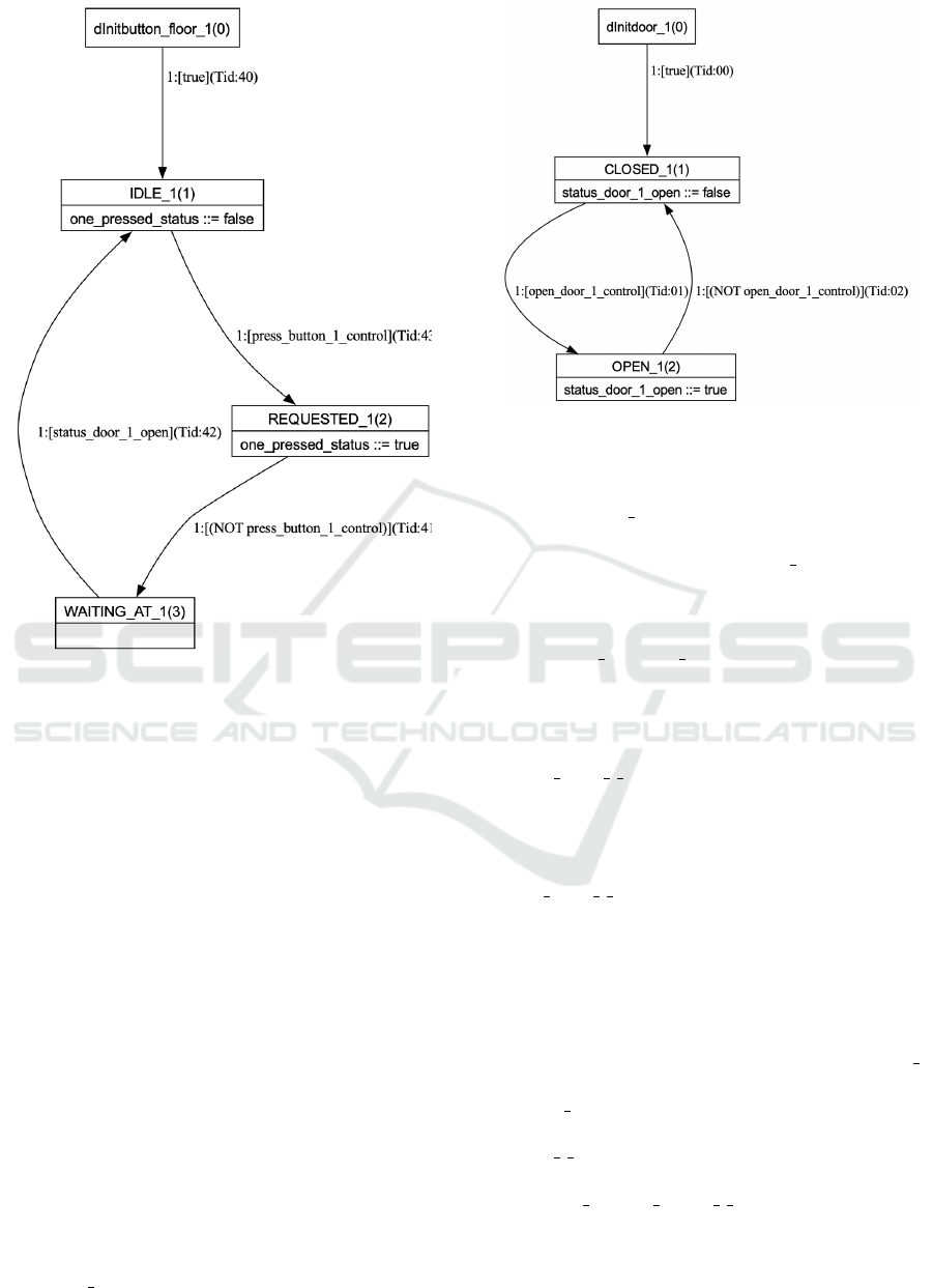
Figure 1: A drawing of the LLFSM for the call button at
level 1.
system starts, all doors are closed. For formal verifi-
cation of the sanity and liveness properties, the litera-
ture (Drozdov et al., 2017; Shatrov, 2021) proposes a
closed-loop model that we also replicate. Thus, once
initialisation is complete, users request the elevator
first in level 1, then in level 2, and finally in level 0.
This proposed test case (Drozdov et al., 2017) does
not stop at level 1 when going to level 2. By contrast,
we do not assume the doors are initially closed. Our
controller not only posts commands for the elevator
to reach level 0, but closes all potentially open doors
during initialisation. This explains our use of the X
operator in the first safety property.
3.2 Messages Without Delays
The first model does not have messaging delays, and
the controller does not consider this; thus, it has no
corrections. Nevertheless, all six properties are valid.
Fig. 1 shows the LLFSM for the call button at
level 1. There will be three analogous LLFSM in the
arrangement corresponding to the call buttons of the
three floors. A call button in floor i is typically in the
state IDLE i unless it receives a control message that a
Figure 2: A drawing of the LLFSM for the door at level 1.
request by a user has been made on that floor. If such
a message is received, this LLFSM will move to the
state REQUESTED i. When the user releases the button
(no longer a control message that it is pressed, this
LLFSM moves to the state WAITING i, until it notices
the status message of the door at level i indicating the
door is open (thus, the request is served). Note that
such call button LLFSM creates a status message, as
the variable i pressed status in the whiteboard.
Fig. 2 shows the LLFSM corresponding to the
door at level 1. A door at level i can either be
CLOSED or OPEN, and this is communicated in a sta-
tus message by updating the whiteboard variable
status door i open (notice that this is the status
that the call button consults). The doors are sub-
ject to the controller that sends them a control mes-
sage to close or open them. For the i-th door, this
is the control message in the whiteboard variable
[open door i control.
The LLFSMs for the sensors that detect whether
the elevator is on their floor are also machines with
two states. Fig. 3 shows the LLFSM corresponding to
the touch-sensor at level 1. There are three machines
modelling each sensor at each level.
The i-sensor has two states. When it is being
pressed by the elevator, it is in the state TOUCHED i,
and when it is not being pressed, it is in the state
ENABLED i. The touch sensor communicates its state
with a status message in the whiteboard variable
sensor i touching. The elevator controls the state
of the touch sensor with a control message on the vari-
able touch sensor floor i control.
The elevator is a more complicated LLFSM, as
shown by Fig. 4.
As per the descriptions of this case study, the
elevator takes four units of time to travel be-
MODELSWARD 2025 - 13th International Conference on Model-Based Software and Systems Engineering
144
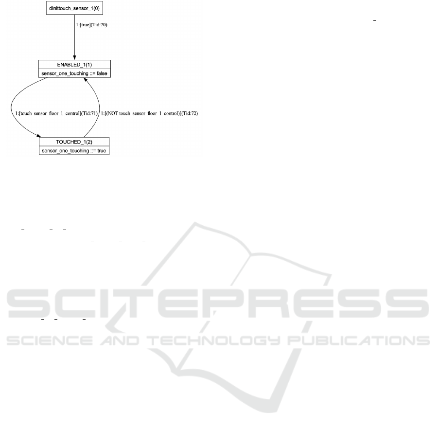
Figure 3: A drawing of the LLFSM for the touch sensor at
level 1.
tween two consecutive floors. It reacts to the
controller’s control messages on its motor. The
elevator moves up when the whiteboard variable
turn motor up control is true, and it moves down
when the variable turn motor down control is true.
The elevator is (a) at one of the three levels, (b) in
between levels lower than the bottom, or (c) higher
than the top level. So as not to use even more
states, three local variables are used to indicate how
far it is when in between levels. For instance,
when between levels one and two, the local variable
distance to floor 1 can have values in {1, 2, 3}.
The simple controller (Fig. 5) does not consider
the possibility of the elevator bypassing a floor since
there are no delays. The elevator’s arrival on a floor
causes sensor detection, and the controller reads the
sensor’s status immediately after.
To complete the arrangement as a closed model,
we have an LLFSM (Fig. 6) that models interaction
with the user and sends the control messages to the
call buttons, waiting for the elevator to arrive before
issuing the following control message.
3.3 Messages with Delays and
Controller Without Corrections
The second model introduces delays parameterised by
a maximum delay of 0, 1, or 2 units (in the litera-
ture (Shatrov and Vyatkin, 2021) the maximum de-
lay is set to 2 units). The delays in the communica-
tion channels are placed as in the literature (Shatrov
and Vyatkin, 2021) between the touch sensors and the
controller. The signal that the elevator is at a particu-
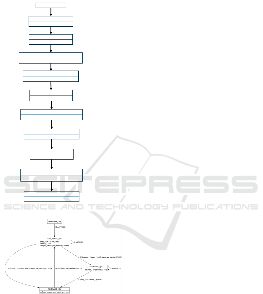
lar floor can be delayed as much as 2 time units. Fig. 7
shows the LLFSM that introduces a delay between the
touch sensor at level 1 and the controller. The sys-
tem now has three of these delaying machines, one
for each touch sensor.
The LLFSM is analogous to a E DELAY function
block presented in Fig. 2 by (Drozdov et al., 2016) or
in Fig. 6 by (Drozdov et al., 2017). The delay is non-
deterministic, meaning it can take any of the values
0, 1, or 2 units and the system shall be correct for all
these possibilities for every message.
Naturally, when the maximum delay is 0, this
model reduces to the earlier model of the previous
section (the delaying LLFSMs participate but have no
effect). But, since the controller assumes no delays,
it is enough for the maximum delay to be 1 for all
properties to be false; thus, with maximum delay 2,
all properties are also false (the trace that makes them
false with maximum delay 1 is a trace for the case
when the maximum delay is 2).
3.4 Messages with Delays and
Controller With Corrections
Our third model incorporates the correction in the
controller into the second model and now, no matter
how we set the maximum delay, all properties are sat-
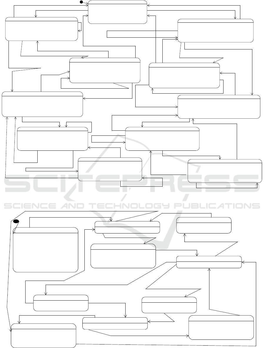
isfied. Fig. 8 shows a fraction of the new controller.
This fraction shows when the elevator departs from
floor 0 to floor 1 or to floor 2. The controller closes
the door at level 0, and then, according to the target
floor, calculates the expected time for the displace-
ment. The status of the calling button gives the tar-
get floor. A signal from a touch sensor at floor 1 or
floor 2 (which may be delayed) is sufficient for the
controller to stop the motor. Analogously to the cor-
rection in the literature, a difference between the ex-
pected travel time and the counting of time defines
how many steps to run the motor in the opposite di-
rection. Once the elevator arrives at a floor, the cor-
responding door is opened, and the elevator becomes
available again. Naturally, the three possible depar-
tures imply a larger controller, that for space reasons
is omitted, but available with our released examples.
3.5 Real-Time Properties
We reproduced the verification of all the safety prop-
erties and liveness properties we found in the liter-
ature. We now show that, with our translation to
SMV, we can verify real-time properties. There are
two types of real-time properties (Lamport, 2002)
(or Bounded Existence (Dwyer et al., 1998)). First,
there are properties that ensure an upper bound on
the length of time for the system to respond. Second,
there are those that ensure a lower bound on the length
of time that an aspect of the state is present. For the
first type of property, we verify that the waiting time
Efficient Modelling with Logic-Labelled Finite-State Machines of IEC 61499 Function Blocks: Simulation, Execution and Verification
145
BELOW_0_WENT_UP
touch_sensor_floor_1_control := false
touch_sensor_floor_2_control := false
touch_sensor_floor_0_control := false
distance_to_floor_1 := (distance_to_floor_1 - 1)
distance_to_floor_2 := (distance_to_floor_2 - 1)
distance_to_floor_0 := (distance_to_floor_0 - 1)
BELOW_0_WENT_DOWN
touch_sensor_floor_1_control := false
touch_sensor_floor_2_control := false
touch_sensor_floor_0_control := false
distance_to_floor_1 := (distance_to_floor_1 + 1)
distance_to_floor_2 := (distance_to_floor_2 + 1)
distance_to_floor_0 := (distance_to_floor_0 + 1)
ABOVE_2_WENT_DOWN
touch_sensor_floor_1_control := false
touch_sensor_floor_2_control := false
touch_sensor_floor_0_control := false
distance_to_floor_1 := (distance_to_floor_1 - 1)
distance_to_floor_2 := (distance_to_floor_2 - 1)
distance_to_floor_0 := (distance_to_floor_0 - 1)
ABOVE_2_WENT_UP
touch_sensor_floor_1_control := false
touch_sensor_floor_2_control := false
touch_sensor_floor_0_control := false
distance_to_floor_1 := (distance_to_floor_1 + 1)
distance_to_floor_2 := (distance_to_floor_2 + 1)
distance_to_floor_0 := (distance_to_floor_0 + 1)
BETWEEN_0_AND_1_WENT_UP
touch_sensor_floor_1_control := false
touch_sensor_floor_2_control := false
touch_sensor_floor_0_control := false
distance_to_floor_1 := (distance_to_floor_1 - 1)
distance_to_floor_2 := (distance_to_floor_2 - 1)
distance_to_floor_0 := (distance_to_floor_0 + 1)
POSITION_FLOOR_0
touch_sensor_floor_0_control := true
touch_sensor_floor_2_control := false
touch_sensor_floor_1_control := false
distance_to_floor_0 := 0
distance_to_floor_1 := TRAVEL_TIME
distance_to_floor_2 := (TRAVEL_TIME + TRAVEL_TIME)
POSITION_FLOOR_2
touch_sensor_floor_2_control := true
touch_sensor_floor_1_control := false
touch_sensor_floor_0_control := false
distance_to_floor_2 := 0
distance_to_floor_1 := TRAVEL_TIME
distance_to_floor_0 := (TRAVEL_TIME + TRAVEL_TIME)
BETWEEN_1_AND_2_WENT_UP
touch_sensor_floor_1_control := false
touch_sensor_floor_2_control := false
touch_sensor_floor_0_control := false
distance_to_floor_1 := (distance_to_floor_1 + 1)
distance_to_floor_2 := (distance_to_floor_2 - 1)
distance_to_floor_0 := (distance_to_floor_0 + 1)
BETWEEN_2_1_WENT_DOWN
touch_sensor_floor_1_control := false
touch_sensor_floor_2_control := false
touch_sensor_floor_0_control := false
distance_to_floor_1 := (distance_to_floor_1 - 1)
distance_to_floor_2 := (distance_to_floor_2 + 1)
distance_to_floor_0 := (distance_to_floor_0 - 1)
BETWEEN_1_AND_0_WENT_DOWN
touch_sensor_floor_1_control := false
touch_sensor_floor_2_control := false
touch_sensor_floor_0_control := false
distance_to_floor_1 := (distance_to_floor_1 + 1)
distance_to_floor_2 := (distance_to_floor_2 + 1)
distance_to_floor_0 := (distance_to_floor_0 - 1)
POSITION_FLOOR_1
touch_sensor_floor_1_control ::= true
touch_sensor_floor_2_control ::= false
touch_sensor_floor_0_control ::= false
distance_to_floor_1 ::= 0
distance_to_floor_2 ::= TRAVEL_TIME
distance_to_floor_0 ::= TRAVEL_TIME
2:(turn_motor_down_control AND (1 < distance_to_floor_2))
2:turn_motor_down_control
2:turn_motor_up_control
1:(turn_motor_up_control AND (1 == distance_to_floor_0))
3:(turn_motor_up_control AND (1 < distance_to_floor_0))
2:turn_motor_down_control
2:(turn_motor_up_control AND (1 < distance_to_floor_0))
1:[(turn_motor_up_control AND (1 == distance_to_floor_0))
3:turn_motor_down_control
2:turn_motor_up_control
1:(turn_motor_down_control AND (1 == distance_to_floor_2))
3:(turn_motor_down_control AND (1 < distance_to_floor_2))
AND (1 == distance_to_floor_2))
1:(turn_motor_down_control
3:turn_motor_up_control
1:turn_motor_up_control
2:turn_motor_down_control
3:(turn_motor_down_control AND (1 == distance_to_floor_0))
2:(turn_motor_up_control AND (1 < distance_to_floor_1))
4:(turn_motor_down_control AND (1 < distance_to_floor_0))
4:(turn_motor_up_control AND (1 < distance_to_floor_1))
4:(turn_motor_down_control AND (1 < distance_to_floor_1))
3:(turn_motor_up_control AND (1 == distance_to_floor_2))
1:(turn_motor_down_control AND (1 == distance_to_floor_0))
3:(turn_motor_down_control AND (1 < distance_to_floor_0))
1:(turn_motor_down_control AND (1 == distance_to_floor_1))
2:(turn_motor_up_control AND (1 == distance_to_floor_1))
1:(turn_motor_up_control AND (1 == distance_to_floor_1))
2:(turn_motor_up_control AND (1 < distance_to_floor_2))
1:(turn_motor_up_control AND (1 == distance_to_floor_2))
2:(turn_motor_down_control AND (1 == distance_to_floor_1))
3:(turn_motor_up_control AND (1 < distance_to_floor_2))
4:(turn_motor_down_control AND (1 < distance_to_floor_1))
1:turn_motor_up_control
2:(turn_motor_down_control)
Figure 4: A drawing of the LLFSM for the elevator.
ARRIVED_AT_TWO
turn_motor_up_control := false
turn_motor_down_control := false
open_door_2_control := true
press_button_2_control := false
ARRIVED_AT_ONE
turn_motor_up_control := false
turn_motor_down_control := false
open_door_1_control := true
press_button_1_control := false
DOOR_CLOSED_MOVING_UP
turn_motor_up_control := true
CLOSING_DOOR_2
open_door_2_control := false
elevator_ready := false
DOOR_1_CLOSING
open_door_1_control := false
elevator_ready := false
DOOR_0_CLOSING
open_door_0_control := false
elevator_ready := false
WAITING_IDLE
elevator_ready := true
ARRIVED_AT_ZERO
turn_motor_down_control := false
turn_motor_up_control := false
open_door_0_control := true
press_button_0_control := false
DOOR_CLOSED_MOVING_DOWN
turn_motor_down_control := true
STARTING
open_door_1_control := false
open_door_2_control := false
open_door_0_control := false
turn_motor_up_control := false
turn_motor_down_control := false
press_button_1_control := false
press_button_2_control := false
press_button_0_control := true
elevator_ready := false
1:((NOT status_door_1_open)
AND zero_pressed_status)
1:(NOT status_door_2_open)
2:((NOT status_door_1_open)
AND two_pressed_status)
(NOT status_door_0_open)
3:(sensor_two_touching
AND (zero_pressed_status OR one_pressed_status))
2:(sensor_zero_touching
AND (one_pressed_status OR two_pressed_status))
1:(sensor_one_touching
AND (zero_pressed_status OR two_pressed_status))
1:sensor_one_touching AND one_pressed_status
2:sensor_two_touching AND two_pressed_status
status_door_2_open
status_door_1_open
status_door_0_open
1:sensor_zero_touching AND zero_pressed_status
2:sensor_one_touching AND one_pressed_status
(NOT status_door_1_open)
AND (NOT status_door_2_open) AND (NOT status_door_0_open)
Figure 5: A drawing of the LLFSM for the controller that does not handle communication delays.
MODELSWARD 2025 - 13th International Conference on Model-Based Software and Systems Engineering
146
dInithmi(0)t
IS_ELEVATOR_READY(1)
PRESS_1(4)
WAITING_FOR_ELEVATOR_AT _1(2)
DOOR_OPENED_AT_ONE(3)
PRESS_2(5)
WAITING_FOR_ELEVATOR_AT_2(6)
DOOR_OPENED_AT_TWO(7)
PRESS_0(8)
WAITING_FOR_ELEVATOR_AT_0(9)
DOOR_OPENED_AT_ZERO(10)
1:[true](Tid:140)
1:[elevator_ready](Tid:142)
1:[one_pressed_status](Tid:143)
1:[status_door_1_open](Tid:141)
1:[true](Tid:144)
1:[two_pressed_status](Tid:145)
1:[status_door_2_open](Tid:146)
1:[true](Tid:149)
1:[zero_pressed_status](Tid:147)
1:[status_door_0_open](Tid:148)
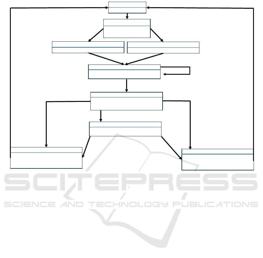
Figure 6: A drawing of the LLFSM for the user interaction.
Figure 7: A drawing of the LLFSM that delays the signal
of the touch sensor at level 1.
once the elevator is called at a floor is bounded by a
constant.
LTLSPEC
G( button_floor_0.At_REQUESTED_0
-> F[0,147] elevator.At_POSITION_FLOOR_0
)
This illustrates that a request for the elevator at
level 0 is serviced by the close model in no more than
147 Kripke states.
For the second type, we verify that once a door is
open, it remains open for at least a certain period.
LTLSPEC
G
( (door_1.At_OPEN_1& X !door_1.At_OPEN_1)
-> H[0,44] door_1.At_OPEN_1
)
This property indicates that door 1 remains open
for at least 44 Kripke states.
3.6 Comparison
Using the Eclipse Modelling Framework, we devel-
oped tools to translate LLFSMs models into SMV and
TLA+ through model-to-text transformations. Our
tools and examples are released as a Docker con-
tainer for ease of installation. The model checker
NuSMV completes the verification of the six proper-
ties for all three models in a matter of minutes. We
replicated this in a machine running Linux with a
CPU i7-10850H,0 and 16GB of RAM and a machine
tuning macOs Sonoma 14.5 with an Apple Arm M1
and 16GB of RAM. In contrast, the SMV model with
time-stamped events in the public domain (Shatrov,
2021) includes a script for verification. Our attempts
to run the verification failed to terminate in machines
with less than 16GB of RAM and required 2 hours
and 20 minutes to verify only one property on both
systems mentioned earlier. Moreover, for this model,
NuSMV raises a warning “Fair states set of the finite
state machine is empty” and the SMV formulation in-
cludes FAIRNESS directives, which raises issues about
the apparent verification of a property because the
property may be true by vacuity.
4 CONCLUSIONS
Whether a language is a domain-specific modelling
language or a general modelling language is in the
eye of the beholder (Wasowski and Berger, 2023).
Although Turing complete, LLFSMs can be consid-
ered a domain specific language tailored to describe
CPSs’ behaviour. LLFSMs are short of describ-
ing data structures or object-oriented mechanisms al-
though there is no reason why LLFSMs can be organ-
ised in inheritance hierarchies and also contain meth-
ods using statements as per the code associated with
states (LLFSMs already contain local variables).
The unambiguous semantics of LLFSMs, com-
bined with control-status messages, improve the reli-
ability of industrial automation and software systems
by eliminating semantic discrepancies. This ensures
Efficient Modelling with Logic-Labelled Finite-State Machines of IEC 61499 Function Blocks: Simulation, Execution and Verification
147
1:[delayed_sensor_zero_touching AND (one_pressed_status OR two_pressed_status](Tid:133)
WAITING_IDLE(2)
elevator ready ::= true
CLOSING_DOOR_0(6)
open_door_0_control ::= false
elevator_ready ::= false
global _clock_counter ::= 0
GOING_FROM_0_TO_2(11)
expected_arrival ::= TRAVEL_TIME+TRAVELTIME
GOING_FROM_0_TO_1(11)
expected_arrival ::= TRAVEL_TIME
DOOR_CLOSED_MOVING_UP(7)
turn_motor_up_control ::= true
global_clock_counter ::= global_clock+1
1:[one_pressed_status AND (NOT status_door_0_open)](Tid:139)
1:[two_pressed_status AND (NOT status_door_0_open)](Tid:1310)
1:[true]Tid:138)
1:[true]Tid:137)
STOP_GOING_UP(7)
turn_motor_up_control ::= false
turn_motor_down_control ::= false
count_back ::= global_clock – expected_arrival
2:[true]Tid:1320)
1:[(one pressed _status AND delayed_sensor_one_touching)
OR
(two_pressed_status AND delayed_sensor_two_touching]Tid:1319)
ARRIVED_AT_TWO(7)
turn_motor_up_control ::= false
turn_motor_down_control ::= false
open_door_2_control ::= true
press_button_2_control ::= false
ARRIVED_AT_ONE(7)
turn_motor_up_control ::= false
turn_motor_down_control ::= false
open_door_1_control ::= true
press_button_1_control ::= false
1:[status_door_1_open]Tid:134)
1:[status_door_2_open]Tid:134)
2:[expected_arrival == global_clock_counter
AND two_pressed_status](Tid:1310)
1:[expected_arrival == global_clock_counter
AND one_pressed_status](Tid:1310)
CORRECT_DOWN(13)
turn_motor_down_control ::= true
count_back ::= count_back -1
3:[expected_arrival < global_clock_counter](Tid:1331)
2:[two_pressed_status
AND (0==count_back](Tid:1331)
1:[one_pressed_status
AND (0==count_back](Tid:1311)
Figure 8: Fraction of the controller LLFSM that detects when the elevator bypasses a target floor and redirects it back.
consistency across different model checkers. Our
tools can translate LLFSM models into multiple pro-
gramming languages, with equivalent traces. While
translations to C and assembly may run at different
speeds, the execution times are proportional, allow-
ing for real-time property verification. Although not
shown here, the action language used in LLFSMs also
supports timed transitions, which allow system calls
to the system clock. Therefore, this introduction of
the LLFSMs approach and its tools for incorporating
them into the IEC 61499 standard is a step towards
even more trustworthy and certifiable distributed sys-
tems.
Software language engineering (SLE) is the ap-
plication of systematic, disciplined, and measurable
approaches to the development, deployment, use,
and maintenance of software (domain-specific) lan-
guages. The technology for this is now heavily reliant
of language workbenches. Language workbenches
are tools for reducing the gap between the design
and implementation of (external) domain-specific lan-
guages. Our tools are currently based on the Eclipse-
Modelling Framework. To modernise them for lan-
guage workbenches, in the future, we plan to shift
them to the GSLP (Metin and Bork, 2023).
REFERENCES
Bencherki, Z., Meyrueis, V., Benfriha, K., Cachot, L., and
Soares, P. (2024). The IEC 61499 standard in industry
4.0. IEEE Int. Conf. Automatic Control and Intelligent
Systems (I2CACIS), p. 24–29.
B
´
erard, B., Bidoit, M., Finkel, A., Laroussinie, F., Petit,
A., Petrucci, L., Schnoebelen, P., and McKenzie, P.
(2001). Systems and Software Verification. Model-
Checking Techniques and Tools. Springer.
Carrillo, M., Estivill-Castro, V., and Rosenblueth, D. A.
(2020b). Verification and simulation of time-domain
properties for models of behaviour. Model-Driven En-
gineering and Software Development Revised Selected
Papers, vol. 1361 CCIS, p. 225–249. Springer.
Cengic, G. and Akesson, K. (2010). On formal analysis
of IEC 61499 applications, part A: Modeling. IEEE
Trans. Industrial Informatics, 6(2):136–144.
Dai, W., Pang, C., Vyatkin, V., Christensen, J. H., and Guan,
X. (2020). Discrete-event-based deterministic execu-
tion semantics with timestamps for industrial cyber-
physical systems. IEEE Trans. Systems, Man, and Cy-
bernetics: Systems, 50(3):851–862.
Drozdov, D., Dubinin, V., Patil, S., and Vyatkin, V. (2021).
A formal model of IEC 61499-based industrial au-
tomation architecture supporting time-aware compu-
tations. IEEE Open J. Industrial Electronics Society,
2:169–183.
MODELSWARD 2025 - 13th International Conference on Model-Based Software and Systems Engineering
148

Drozdov, D., Patil, S., Dubinin, V., and Vyatkin, V. (2016).
Formal verification of cyber-physical automation sys-
tems modelled with timed block diagrams. IEEE 25th
Int. Symposium on Industrial Electronics (ISIE), pages
316–321.
Drozdov, D., Patil, S., Dubinin, V., and Vyatkin, V. (2017a).
Towards formal verification for cyber-physically ag-
nostic software: A case study. IECON 43rd An-
nual Conf. IEEE Industrial Electronics Society, pages
5509–5514.
Dubinin, V. N. and Vyatkin, V. (2012). Semantics-robust
design patterns for IEC 61499. IEEE Trans. Industrial
Informatics, 8(2):279–290.
Dwyer, M. B., Avrunin, G. S., and Corbett, J. C. (1998).
Property specification patterns for finite-state verifica-
tion. Proc. Second Workshop on Formal Methods in
Software Practice, FMSP, p. 7–15, NY, USA. ACM.
International Electrotechnical Commission (IEC) (2012).
IEC 61499-1:2012 Function blocks - Part 1: Archi-
tecture.
Kopetz, H. (2011). Real-Time Systems: Design Principles
for Distributed Embedded Applications. Springer, 2nd
edition.
Lamport, L. (2002). Specifying Systems: The TLA+ Lan-
guage and Tools for Hardware and Software Engi-
neers. Addison-Wesley, USA.
Lindgren, P., Lindner, M., Lindner, A., Vyatkin, V., Pereira,
D., and Pinho, L. M. (2015). A real-time semantics for
the IEC 61499 standard. IEEE 20th Conf. on Emerg-
ing Technologies & Factory Automation (ETFA), p. 1–
6.
McColl, C., Estivill-Castro, V., McColl, M., and Hexel,
R. (2022a). Decomposable and executable models
for verification of real-time systems. 9th Int. Conf.
Revised papers form Model-Driven Engineering and
Software Development MODELSWARD, vol 1708 of
CCIS, p. 135–156. Springer.
Merz, S. (2008). An introduction to model checking. Mod-
eling and Verification of Real-Time Systems: For-
malisms and Software Tools, p. 81–116. Wiley.
Metin, H. and Bork, D. (2023). On developing and operat-
ing GLSP-based web modeling tools: Lessons learned
from BIGUML. 2023 ACM/IEEE 26th Int. Conf.
Model Driven Engineering Languages and Systems
(MODELS), p. 129–139, IEEE Comp. Soc.
Meyers, B., Vangheluwe, H., Denil, J., and Salay, R.
(2020). A framework for temporal verification support
in domain-specific modelling. IEEE Trans. Software
Engineering, 46(4):362–404.
Pang, C., Patil, S., Yang, C.-W., Vyatkin, V., and Shalyto,
A. (2014). A portability study of IEC 61499: Seman-
tics and tools. 2014 12th IEEE Int. Conf. Industrial
Informatics (INDIN), pages 440–445.
Patil, S., Dubinin, V., and Vyatkin, V. (2015). Formal verifi-
cation of IEC61499 function blocks with abstract state
machines and SMV – modelling. 2015 IEEE Trust-
com/BigDataSE/ISPA, vol 3, p. 313–320.
Provan, G. (2024). Formal methods for autonomous vehi-
cles. IT Professional, 26(1):50–56. Reproduced in the
Column on Formal Methods in Industry, IEEE Com-
puting Edge.
Shatrov, V. (2021). INDIN2021 — examples of two IEC
61499 systems for comparison of formal verification
approaches. On github. https://github.com/vi34/
conf/tree/main/INDIN2021.
Shatrov, V. and Vyatkin, V. (2020). Formal verification of
IEC 61499 enhanced with timed events. Technolog-
ical Innovation for Life Improvement, IFIP Advances
in Information and Communication Technology, vol
577, p. 168–178. Springer.
Shatrov, V. and Vyatkin, V. (2021). Promela formal mod-
elling and verification of IEC 61499 systems with
comparison to SMV. IEEE 19th Int. Conf. on Indus-
trial Informatics (INDIN), pages 1–6.
Sinha, R., Patil, S., Gomes, L., and Vyatkin, V. (2019). A
survey of static formal methods for building depend-
able industrial automation systems. IEEE Trans. In-
dustrial Informatics, 15(7):3772–3783.
Vyatkin, V. (2009). The IEC 61499 standard and its seman-
tics. IEEE Industrial Electronics Magazine, 3(4):40–
48.
Vyatkin, V. (2011). IEC 61499 as enabler of distributed and
intelligent automation: State-of-the-art review. IEEE
Trans. Industrial Informatics, 7(4):768–781.
Vyatkin, V., Pang, C., and Tripakis, S. (2015). Towards
cyber-physical agnosticism by enhancing IEC 61499
with PTIDES model of computations. IECON 41st
Annual Conf. IEEE Industrial Electronics Society, p.
001970–001975.
Wasowski, A. and Berger, T. (2023). Domain-Specific Lan-
guages: Effective modeling, automation, and reuse.
Springer.
Xavier, M., Patil, S., and Vyatkin, V. (2021). Cyber-
physical automation systems modelling with
IEC 61499 for their formal verification. IEEE
19th Int. Conf. Industrial Informatics (INDIN), pages
1–6.
Efficient Modelling with Logic-Labelled Finite-State Machines of IEC 61499 Function Blocks: Simulation, Execution and Verification
149
