
Tutrace: Editable Animated Vector Shape from Video
Lo
¨
ıc Vital
a
Technicolor Group, France
Keywords:
Video, Vectorization, Rotoscopy, Animation, Vector Graphics.
Abstract:
We present a new video vectorization technique for converting a sequence of binary images into an animated
vector shape. Our approach offers the benefit of producing an output that can be directly used in a compositing
software to apply manual edits and corrections, which is often a mandatory constraint for rotoscoping artists
in the VFX industry. Our process initially builds a frame-by-frame vectorization of the input, finds correspon-
dences between vertices at different frames, and extracts an animated vector shape from the induced graph
structure. Although the presented method is completely automatic, the general approach is flexible and offers
several controls to adjust the fidelity vs. simplicity trade-off in the generated output.
1 INTRODUCTION
In the visual effects (VFX) industry, rotoscoping
artists work primarily with animated shapes (closed
or open 2D curves) as these vector graphics primitives
provide fine control over the final result and allow re-
editing in case of feedback from clients, supervisors
or downstream departments. However, using these
animated shapes comes at a cost, as they require sev-
eral hours of careful manual work from trained artists
to be initially created.
On the other hand, image segmentation methods
have matured in the recent years, and it is now pos-
sible to automatically extract a desired object from a
video with great precision in a number of scenarios.
However the lack of control and ability to edit the re-
sults is currently making it difficult for VFX studios
to integrate these methods in their standard workflow.
In this work, we propose a method to bridge this
gap, i.e. turn a segmented video (made out of binary
images) into an animated vector shape, which can be
imported in a compositing DCC
1
such as Nuke or Sil-
houette for re-editing. We call this method Tutrace.
This name originated as a blend between the initial
inspiration for the algorithm, Potrace, and the topol-
ogy of the output, which resembles a tube or tunnel.
The fact that we are targeting DCC-compatible
animated vector shapes imposes some specific con-
a
https://orcid.org/0009-0002-7972-9242
1
Digital Content Creator, i.e. software dedicated to cre-
ating and editing digital content such as 2D/3D geometry,
images, etc.
straints on the structure of the output. More precisely,
this means we must produce closed curves whose ge-
ometry is specified by a set of keyframes, i.e. frame
values along the timeline where the positions of all
control points are prescribed. Using this representa-
tion, the curve geometry in-between two keyframes is
determined by interpolating the control points posi-
tions.
The main challenge imposed by this structure is
that the number of vertices is fixed for the entire frame
range. By contrast, applying a single-image vector-
ization algorithm to each frame independently would
create vector shapes with a varying number of ver-
tices, adapted to the input geometry. This is particu-
larly visible in areas where details appear or disappear
over the animation: a flat area needs only two vertices
to be represented, but if this area breaks into several
parts then more vertices are needed.
Our algorithm works by first vectorizing each
video frame independently, then finding correspon-
dences between these initial static vector shapes to
extract an animated vector shape, and finally simpli-
fying it. Our main contribution lies in the central part
of this algorithm, which is the process of going from
a sequence of static vector shapes to an animated vec-
tor shape, thus solving the problem stated above using
an ad-hoc method. The simplifications performed af-
terwards on the animated shape aim at reducing its
complexity, i.e. the number of animated vertices and
keyframes, thus making the output better suited for
manual editing.
Vital, L.
Tutrace: Editable Animated Vector Shape from Video.
DOI: 10.5220/0013097900003912
Paper published under CC license (CC BY-NC-ND 4.0)
In Proceedings of the 20th International Joint Conference on Computer Vision, Imaging and Computer Graphics Theory and Applications (VISIGRAPP 2025) - Volume 1: GRAPP, HUCAPP
and IVAPP, pages 19-28
ISBN: 978-989-758-728-3; ISSN: 2184-4321
Proceedings Copyright © 2025 by SCITEPRESS – Science and Technology Publications, Lda.
19
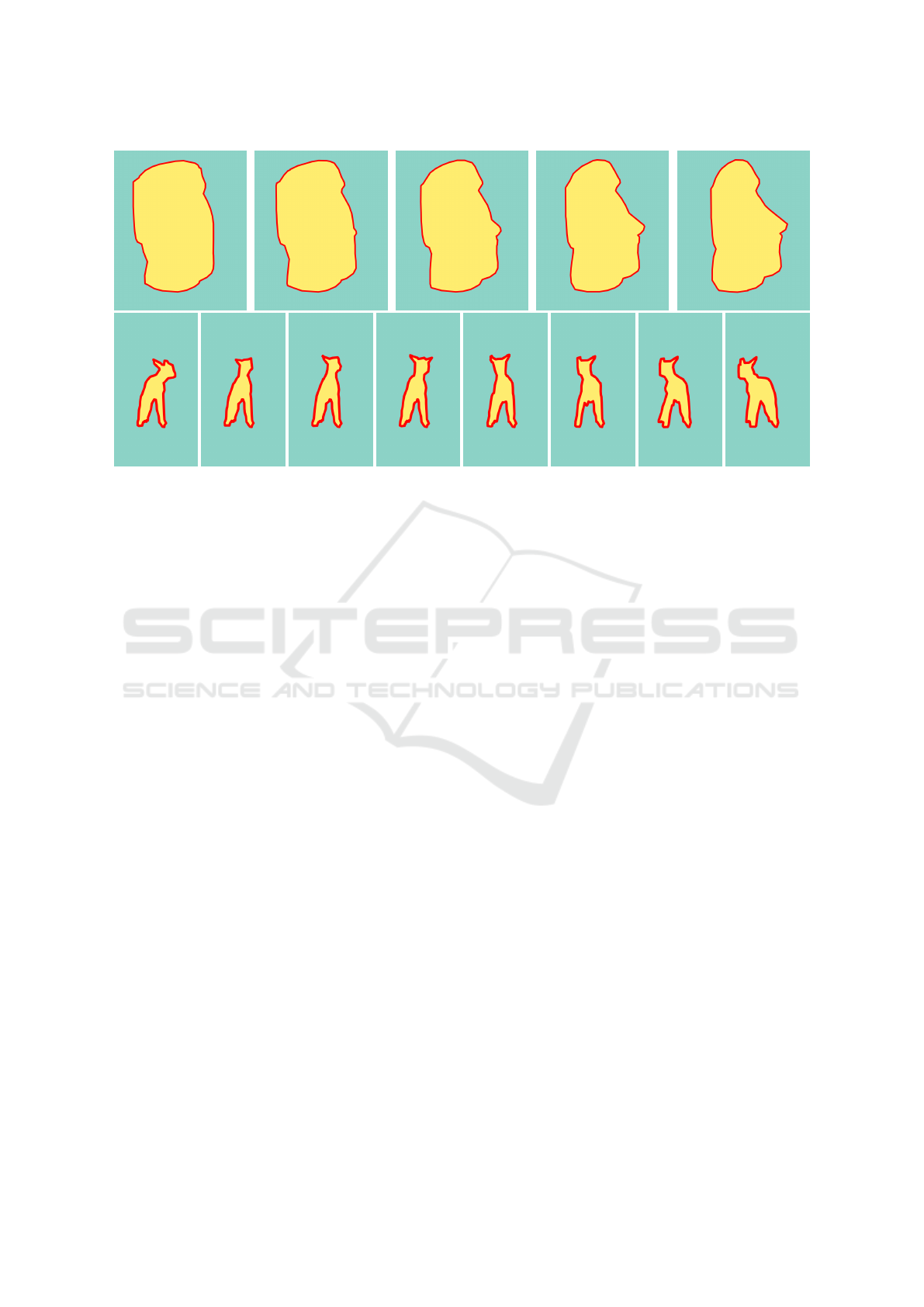
Figure 1: Animated vector shapes generated by Tutrace on the “statue” (first row) and “sheep” (second row) sequences, shown
in red and overlaid on the images.
2 RELATED WORK
2.1 Video Object Segmentation
Image segmentation and object segmentation in video
are fundamental problems in computer vision, and
there is now extensive literature on that topic (Yu
et al., 2023) (Yao et al., 2020). Going from object
segmentation in a single image to a sequence of im-
ages is not a trivial task, as temporal coherence has to
be taken into account, and many artifacts can arise.
In this article, we do not present any new seg-
mentation method: this work is complementary to
segmentation, as it takes a binary image sequence as
input and produces an animated vector shape. The
motivation behind this is to provide users with direct
control over the results of an automatic segmentation
process, rather than relying on implicit controls.
2.2 Image Vectorization
There has been much work on single-image vectoriza-
tion, with various algorithms and representations pro-
posed to cover a wide range of inputs: natural images,
cartoon, manga, line drawings (Favreau et al., 2016),
and even pixel art (Kopf and Lischinski, 2011).
These methods can be classified into two main
categories depending on the representation they work
with, namely meshes or curves. Mesh-based meth-
ods span a wide range of primitives, including Fergu-
son patches (Sun et al., 2007) and triangular B
´
ezier
patches (Xia et al., 2009). The curve-based methods
also include various primitives, for instance closed
polygons and B
´
ezier curves (Selinger, 2003) as well
as diffusion curves (Orzan et al., 2008).
In this work, we focus particularly on the context
of rotoscopy, thus adding the constraint that we must
be able to import and edit the vectorization result in a
compositing DCC. Therefore the set of possible prim-
itives we can use is reduced to closed curves, thus
making Potrace (Selinger, 2003) an adequate choice
to base our work on.
2.3 Video Vectorization
Several methods have already been proposed for
video vectorization, however they do not focus on the
same objectives as we do.
(Zhang et al., 2009) proposes a method specifi-
cally tailored for cartoon animation, and focuses on
decomposing the input images into spatially and tem-
porally coherent regions. However the final output
it generates is a frame-by-frame vectorization, not an
animated shape.
(Wang et al., 2017) takes a quite different ap-
proach: it considers the input video as a volume with
color information, and the vectorization as a tetrahe-
dral meshing problem. This approach greatly simpli-
fies the spatial-temporal duality and offers a link be-
tween vectorization and the wide literature on mesh
processing, however the output it generates is a tetra-
hedral mesh, which is not usable in any composit-
ing DCC and not easily convertible into an animated
shape.
GRAPP 2025 - 20th International Conference on Computer Graphics Theory and Applications
20

(Li et al., 2021) proposes a method based on dif-
fusion curves, producing results of great visual qual-
ity, using a combination of optical flow and shape
matching techniques for temporal coherence. How-
ever once again the output is not an animated shape,
but a frame-by-frame vectorization. In addition, the
output is made out of diffusion curves, which do not
have any topology constraint, and therefore generally
do not form a closed curve, therefore making the out-
put of this algorithm unfit to be used in ours.
(Zhang et al., 2023) focuses on motion graphics
video, i.e. animated graphic designs. They address
the problem of motion tracking and layered decompo-
sition, which is of critical importance whenever multi-
ple objects are in the scene. The output they produce,
however, is not a vector shape: each tracked object
is associated with an image inferred from the video
input, called its canonical image, a sequence of per-
frame affine transforms and a sequence of per-frame
z-index depth. In particular, this representation im-
plies that their approach does not handle change in
the objects themselves, such as details appearing and
disappearing throughout the animation, which occurs
quite frequently in the context of rotoscopy and must
not be put aside.
3 MOTIVATION AND OVERVIEW
3.1 Problem Statement
The input data we consider in this work is a finite se-
quence of images (I
f
)
0≤ f <F
where F is the number
of frames. All these images share the same dimen-
sions (w, h). In this article we do not take color into
account, we only treat binary images, i.e. images with
pixel values in the set {0, 1}.
We also make another strong assumption on these
images: we assume that in each image, the pixels with
value 1 form a connected component without hole.
We call this component the content of the image. This
assumption greatly simplifies the topology of the ani-
mated content.
The output we want to produce is an animated
shape, i.e. a closed curve defined by a sequence of N
vertices animated over K keyframes. Each keyframe
defines a fixed 2D position for the vertices, and for
a given frame in-between two keyframes the vertices
positions are linearly interpolated to determine the
shape geometry on that frame. Note that such an an-
imated shape is not necessarily a polygon: the ver-
tices could also be interpreted as control points for a
smooth curve. However, in the work that follows, we
will focus on generating an animated polygon.
3.2 Algorithm Breakdown
The overall workflow of the algorithm is quite intu-
itive: we start by vectorizing each image indepen-
dently, then we match the vertices between consec-
utive frames to create animated vertices, thus forming
an animated shape.
However most single-image vectorization algo-
rithms will try to simplify the shape geometry by
removing vertices in “flat” areas, which is problem-
atic for the matching phase. Indeed, if a portion of
the shape is flat at a given frame but “breaks into
two parts” at the following frame, hence creating a
new vertex at the breaking point, we won’t be able
to match this new vertex against the shape at the first
frame (see Figure 3a). To overcome this issue, we
make sure that the first vectorization step produces a
sequence of densely sampled shapes (see Figure 3b)
and we delay the simplification step until the end of
the algorithm, when we have a fully animated shape.
We refer to this final simplification step as pruning.
In addition, it is quite likely that the matching
phase does not produce 1-to-1 vertex matches be-
tween consecutive frames, which makes the process
of creating animated vertices and joining them into
an animated shape more complex than simply chain-
ing the matches. We call this process untangling.
In summary, our algorithm follows these four
steps, depicted in Figure 2: extract a dense contour
from each image, match the vertices of these contours
between consecutive frames, untangle these matches
to produce an animated shape, and prune the animated
vertices and keyframes on this animated shape.
3.3 Data Structure
The data structure we use in our method is a simpli-
fied version of the work presented in (Dalstein et al.,
2015), which we will call a Tutrace complex.
At the most abstract level, a Tutrace complex is
just a directed graph. A node in this graph is called
a key vertex, and it encodes both a 2D position and a
frame number. As for the edges in this graph, they are
split into two categories: the key edges and the tempo-
ral edges. A key edge always links two key vertices
which have the same frame number, whereas a tempo-
ral edge always links two key vertices with different
frame numbers, and is directed from lower to higher
frame number.
This graph structure is enriched with additional
entities which provide higher-level structures and se-
mantic for working with a Tutrace complex. A key
cycle is a looping path of key edges, and can be seen
as a static vector shape (made out of a single closed
Tutrace: Editable Animated Vector Shape from Video
21
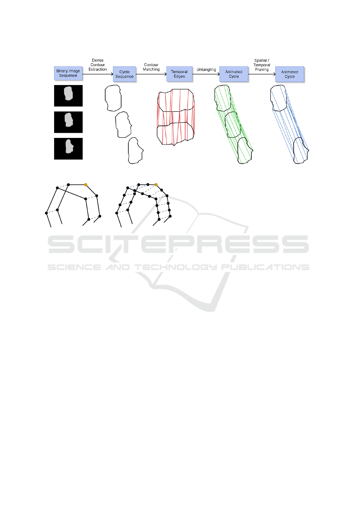
Figure 2: Overview of the Tutrace algorithm.
(a) (b)
Figure 3: Contour matching. Solid lines represent contours
and dashed lines represent matches. (a) Sparse contour. In
this case, there is no good candidate vertex to match the
highlighted vertex. (b) Dense contour. Here, finding a good
match for the each vertex becomes possible.
curve). A key cycle naturally inherits the frame num-
ber of its key edges. A sequence of key cycles with
increasing frame numbers is called a cycle sequence.
An animated vertex is a path of temporal edges. A
circular sequence of animated vertices is called an an-
imated cycle, and can be seen as an animated vector
shape.
4 DENSE CONTOUR
The first step of our algorithm is the extraction of
dense contours. This routine will run on each image
separately, and is very similar to a single-image vec-
torization algorithm, the main difference being that
we wish to keep a dense and regular sampling of
points along the resulting shape.
4.1 Contour Extraction
For a given image, this phase begins by tracing the im-
age’s content, i.e. it generates a closed polygon curve
that follows the boundary of the content’s pixels (see
Figure 4a).
This polygon is the most densely sampled shape
we can get, however since it follows the exact bor-
der of the pixels it also contains some high-frequency
details that we would like to get rid of (staircase ef-
fect) as they do not play a part in the actual shape we
perceive.
4.2 Contour Simplification
We add to this first tracing step a constrained simpli-
fication step, i.e. a simplification step that obeys the
following constraints: for any two consecutive points
p, q on the output polygon, ||p − q||
2
< d
max
, with
d
max
a parameter of the algorithm (see Figure 4b).
To perform this constrained simplification we de-
cided to use an iterative algorithm that progressively
decimates edges on the polygon while always respect-
ing the constraint. The decimation is done by us-
ing a 2D adaptation of the edge-contraction technique
based on quadric error metric, introduced in (Garland
and Heckbert, 1997). However, we add an eligibil-
ity condition on edges: we only consider an edge for
contraction if, once contracted, it would not create a
new edge longer than d
max
.
This algorithm has one main weakness: it may re-
move meaningful details if they are smaller than d
max
.
To solve this issue, we use the geometrical interpre-
tation of the quadric error metric: it measures the
distance to the lines formed by neighboring edges.
Therefore, in order to keep small details, we add a
second constraint to mark an edge e as eligible: we
ask for its contraction error to be under a given thresh-
old err
max
.
GRAPP 2025 - 20th International Conference on Computer Graphics Theory and Applications
22

(a) (b)
Figure 4: The two substeps of the dense contour extraction
phase. (a) The border of the image content is extracted, pro-
ducing a perfectly accurate shape. (b) This shape is simpli-
fied to smooth out staircase artifacts. The density constraint
imposes that all edges are smaller than d
max
.
5 CONTOUR MATCHING
The second step of our algorithm is the matching
of vertices between consecutive frames. Consider a
frame 0 ≤ f < F, we denote the dense contour ex-
tracted from I
f
as C
f
= {v
f ,0
, ..., v
f ,n
f
−1
} where each
v
f ,i
is a vertex of the dense contour polygon, inter-
preted as a 2D point. For 0 ≤ f < F − 1, the prob-
lem of matching C
f
with C
f +1
can be seen as finding
for each v
f ,i
a corresponding vertex v
f +1, j
. Note that
this matching is asymmetric, however this can be cor-
rected by also matching C
f +1
with C
f
: this will en-
sure that reading the sequence forward or backward
will lead to the same result.
An intuitive way to match v
f ,i
would be to find
its nearest neighbor in C
f +1
. However this approach
lacks robustness and leads to unwanted results in
many simple cases. Since we are trying to vectorize a
coherent object moving across a sequence of images,
we can assume that its displacement from one frame
to the next one is “small”. We approximate this small
displacement by a rigid transform on the dense con-
tours. Therefore we can apply a rigid point-set regis-
tration technique to find a rigid transform T : R
2
→ R
2
that best fits C
f
onto C
f +1
. Once we have T , we can
match v
f ,i
with C
f +1
by finding its nearest neighbor
in T
−1
(C
f +1
).
To perform the rigid point-set registration we use
the ICP algorithm (Besl and McKay, 1992), and we
denote by n
iter
the number of ICP iterations. This
method has the advantage of being fast and simple to
implement. In the case where the displacements be-
tween consecutive contours cannot be approximated
by rigid transforms, we can replace the ICP with more
generic point-set registration methods, such as Coher-
ent Point Drift (Myronenko and Song, 2010).
(a) (b)
Figure 5: In a situation like the one depicted in (a), the
untangling algorithm should favor selecting the animated
vertices a → c → d and b → c → e over a → c → e and
b → c → d. Indeed, in the second scenario the animated
vertices are crossing each other, resulting in a twist artifact
as depicted in (b).
6 UNTANGLING
The third step of our algorithm consists in untangling
the matches, i.e. extracting an animated cycle from
the Tutrace complex we have built so far.
Since the objective of this step is to only change
how the data is structured, we wish to minimize its
impact on the final geometry, i.e. keep as many an-
imated vertices as possible, well spread over the en-
tire shape. However we cannot simply keep all the
animated vertices as some of them can “cross” each
other, as shown in Figure 5. In this section we present
an ad-hoc method for extracting animated vertices
which ensures that there will be no such artifact in
the animated cycle.
6.1 Generating Animated Vertices
One way to build animated vertices from the input
data is to compute paths of key vertices connected
with temporal edges. Each path should start at the
first frame and end at the last frame. The correspond-
ing animated vertices thus have one key vertex per
frame.
Generating these animated vertices simply
amounts to computing all the paths linking a key
vertex at the first frame to a key vertex at the last
frame, which can be achieved with a graph traversal
algorithm. Note that two animated vertices can
potentially share one or more key vertices.
6.2 Circular Ordering and Intervals
Having generated this set of animated vertices, the
core problem of untangling is to select a subset and
structure it in a circular sequence.
For a given frame f let’s denote by kc
f
the in-
put key cycle at f and (kv
f ,i
)
0≤i<N
f
its key vertices
indexed in circular order. In addition, for a given ani-
mated vertex av, let’s denote by av( f ) the key vertex
Tutrace: Editable Animated Vector Shape from Video
23

lying on av at frame f .
Now imagine we select some animated vertices
(av
j
)
0≤ j<N
, thus forming an animated cycle ac,
which can also be seen as a directed graph with an-
imated vertices as nodes and edges inherited from the
circular ordering. At frame f , we want the induced
subset of key vertices (av
j
( f ))
0≤ j<N
to respect the
circular ordering of kc
f
.
Because of the cyclic nature of the problem, we
cannot say that a key vertex is before or after another
one. However we can say that a key vertex is between
two others if it lies on the path of key edges that con-
nects them. We call key vertex interval between two
key vertices kv and kv
′
(denoted [kv, kv
′
]) the ordered
sequence of key vertices which lie between kv and kv
′
.
Similarly, we call animated vertex interval between
two animated vertices av and av
′
(denoted [av, av
′
])
the ordered sequence of animated vertices which lie
on the path from av to av
′
in ac. Equipped with these
new notions, we can now say that ac respects the cir-
cular ordering of kc
f
if (and only if) for each ani-
mated vertex interval [av, av
′
] the induced key vertex
sequence at frame f is a sub-sequence of key vertex
interval [av( f ), av
′
( f )].
6.3 Divide-and-Conquer Approach
Let’s consider a key vertex interval [a, b] and a key
vertex c ∈ [a, b]. We can measure its distance to the
interval bounds by taking the maximum between the
length of the key edge path a → ... → c and the key
edge path c → ... → b. Going further, we can define an
interval mid-point as a key vertex minimizing the dis-
tance to the bounds. This mid-point definition can be
extended to animated vertex intervals by taking an an-
imated vertex that minimizes the maximum distance
to the bounds over all frames.
Being able to extract a mid-point from an ani-
mated vertex interval allows us to split it into two
smaller “balanced” parts, and thus provides a way
to construct an animated cycle using a divide-and-
conquer approach (see Algorithm 1 for pseudo-code).
For the initialization, we select an arbitrary animated
vertex av
re f
, add it to the animated cycle ac, and we
exceptionally consider that the interval [av
re f
, av
re f
]
contains all the generated animated vertices. Then,
for each considered interval, we select a mid-point,
add it to ac in-between the interval bounds - thus nat-
urally creating the circular order of ac and respecting
the circular order of the key cycles - and recursively
continue on the two sub-intervals created. The ter-
mination condition for the recursion is met when the
interval is only constituted of its own bounds.
Data: AV : set of animated vertices
Result: ac: animated cycle
ac
:
= empty circular list;
Q
:
= empty FIFO structure;
av
re f
:
= arbitrary element of AV ;
insert av
re f
in ac;
append (av
re f
, av
re f
, AV ) to Q;
while Q is not empty do
av
start
:
= animated vertex;
av
end
:
= animated vertex;
I
:
= animated vertex interval;
pop 1
st
element of Q into
(av
start
, av
end
, I);
if I contains only av
start
and av
end
then
continue to the next iteration;
end
find mid-point av
mid
∈ I that minimizes
the maximum distance to av
start
and
av
end
;
insert av
mid
in ac between av
start
and
av
end
;
append (av
start
, av
mid
, [av
start
, av
mid
]) to
Q;
append (av
mid
, av
end
, [av
mid
, av
end
]) to Q;
end
Algorithm 1: Pseudo-code for animated cycle extraction
from the generated animated vertices during untangling.
7 PRUNING
The fourth step of the algorithm is the simplification
of the animated cycle generated during the untangling
step. We can perform two kinds of operations to sim-
plify an animated shape: either remove an animated
vertex or remove a keyframe (i.e. all the key vertices
at a given frame). We divide this step into two distinct
pass: a spatial pass that removes animated vertices,
and a temporal pass that removes keyframes.
7.1 Spatial Pruning
In the spatial pruning pass, we interpret the animated
cycle as a directed circular graph where the nodes are
the animated vertices. We then apply an algorithm
similar to what is done in Potrace (Selinger, 2003):
1. we assign to each edge a weight w
base
2. for each path u → ... → v in the original graph of
length at most l
max
we create a new directed edge
u → v and assign it a weight equal to w
base
plus the
maximum geometric error made by short-cutting
the path u → ... → v with the path u → v over all
frames
GRAPP 2025 - 20th International Conference on Computer Graphics Theory and Applications
24
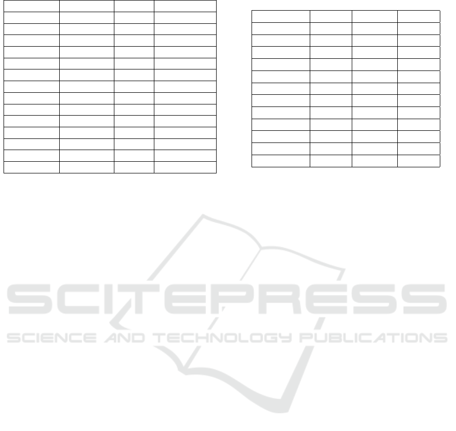
Table 1: Description of evaluation dataset.
Name Dim Frames Source
airplane 1920x1080 50 Synthetic
birdfall 259x327 30 SegTrack V2
blackswan 1920x1080 50 DAVIS 2017
cactus 720x1080 30 Synthetic
car-shadow 1920x1080 40 DAVIS 2017
house 640x480 20 Synthetic
parachute 414x352 51 SegTrack V2
paragliding 1920x1080 70 DAVIS 2017
penguin 384x212 42 SegTrack V2
rallye 1920x1080 50 DAVIS 2017
shark 1080x720 30 Synthetic
sheep 1920x1080 68 DAVIS 2017
statue 640x480 20 Synthetic
worm 480x264 244 SegTrack V2
3. we compute a circuit in this graph that minimizes
the sum of weights, which becomes the new ani-
mated shape.
The main idea behind this algorithm is that we will
shortcut the redundant vertices in areas that remain
flat over the entire animation because the error will be
low.
7.2 Temporal Pruning
In the temporal pruning pass, we view the animated
cycle as a sequence of F key cycles, and we interpret
each key cycle as a vector in R
2n
(with n the number
of animated vertices) by stacking the position of the
animated vertices at a given frame. Using this rep-
resentation we can apply a generalized version for
arbitrary dimension of the Ramer-Douglas-Peucker
line simplification algorithm introduced in (Douglas
and Peucker, 1973). We will denote by θ
k f
the er-
ror threshold parameter in the RDP algorithm. This
technique will produce a set of keyframes to keep in
our animated shape, and we can then remove the dis-
carded ones.
The intuition here is that we will remove
keyframes in frame ranges where they can be well ap-
proximated by linear interpolation.
8 EXPERIMENTAL RESULTS
We evaluated our method on a variety of binary image
sequences. Our dataset (Vital, 2024) contains videos
coming from 3 different sources, as it allows us to
cover a wide range of input properties (see Table 1):
synthetic sequences made by rendering only the matte
layer of 3D objects, sequences coming from the Seg-
Track V2 dataset (Li et al., 2013) and sequences com-
Table 2: Rasterization error comparison. Rasterization er-
rors have been mutliplied by 10
4
for readability.
Name Potrace VTracer Tutrace
airplane 96 4 5
birdfall 37 4 13
blackswan 275 7 11
car-shadow 96 3 13
house 35 16 25
parachute 67 6 10
paragliding 38 0 2
penguin 81 13 22
rallye 35 1 11
shark 239 11 21
sheep 133 2 4
statue 188 9 16
ing from the DAVIS 2017 dataset (Pont-Tuset et al.,
2017).
8.1 Comparison with Frame-by-Frame
Vectorization
We compare our results to what would be obtained
by vectorizing each frame independently. The output
of such a process is not an animated vector shape but
a sequence of static vector shapes, however we can
still compare the rasterization error, i.e. the per-pixel
difference between the input images and the images
obtained by rasterizing the vector shapes.
For the comparison, we use two different vector-
ization algorithms: Potrace (Selinger, 2003) which
has been in use for years in software such as Inkscape,
and VTracer (Pun and Tsang, 2020) which is a more
recent alternative to Potrace. For Potrace, we set the
α
max
parameter to 0 to generate only polygonal out-
puts, and we disable the curve optimization. Simi-
larly for VTracer we set the output mode to “poly-
gon”. For Tutrace, we use the following parameters:
d
max
= 20, err
max
= 2, n
iter
= 20, l
max
= 5, w
base
= .5,
and θ
k f
= 3.
It is important to note that even though these tests
provide a good basis for comparison, comparing two
different structures has some limitations: for instance,
we cannot use the number of keyframes in the ani-
mated vector shape as a metric, even though it is an
important factor in the final quality.
The evaluation results are displayed in Table 2,
which shows that our method performs quite well
in terms of rasterization error: the results are not as
good as VTracer, but this was expected since frame-
by-frame vectorization has no temporal constraint to
satisfy, however we still out-perform Potrace on every
sequence.
The number of animated vertices generated by
Tutrace: Editable Animated Vector Shape from Video
25
(a) 73 / 10 (b) 73 / 6 (c) 44 / 5 (d) 28 / 4
(e) 161 / 19 (f) 161 / 11 (g) 73 / 13 (h) 73 / 9
(i) 35 / 23 (j) 20 / 12 (k) 20 / 9 (l) 20 / 4
Figure 6: Varying pruning parameters on the “statue”, “car-
shadow” and “parachute” sequences to generate simpler
outputs. Figures are annotated like so: number of animated
vertices / number of keyframes.
our method is comparable to the average number of
vertices generated by Potrace but generally higher
than VTracer. Once again this was expected since
our method has to account for changing geometry
throughout the animation. However if we consider
the output complexity, i.e. the total number of control
points used to define the shapes, we remark that Tu-
trace is more compact than Potrace on all sequences,
and more compact than VTracer on all sequences ex-
cept 3, namely “blackswan”, “paragliding” and “ral-
lye”.
This experimental comparison shows that, in addi-
tion to generating a very specific and constraining ge-
ometric structure, Tutrace offers a good compromise
between output quality and complexity.
8.2 Fidelity vs. Simplicity Trade off
The final pruning step of our method offers the pos-
sibility to control the complexity of the generated an-
imated shape. The less complex an animated shape
is, the larger the rasterization error. However in some
applications it can be beneficial to be able to gener-
ate coarser shapes, as they are easier to work with.
As shown in Figure 6, by manipulating the pruning
parameters one can obtain various levels of simplifi-
cation and thus easily generate a shape with the ap-
propriate complexity.
8.3 Limitations and Failure Cases
As can be seen in Table 2, two sequences from the
dataset were not present in the comparison: cactus
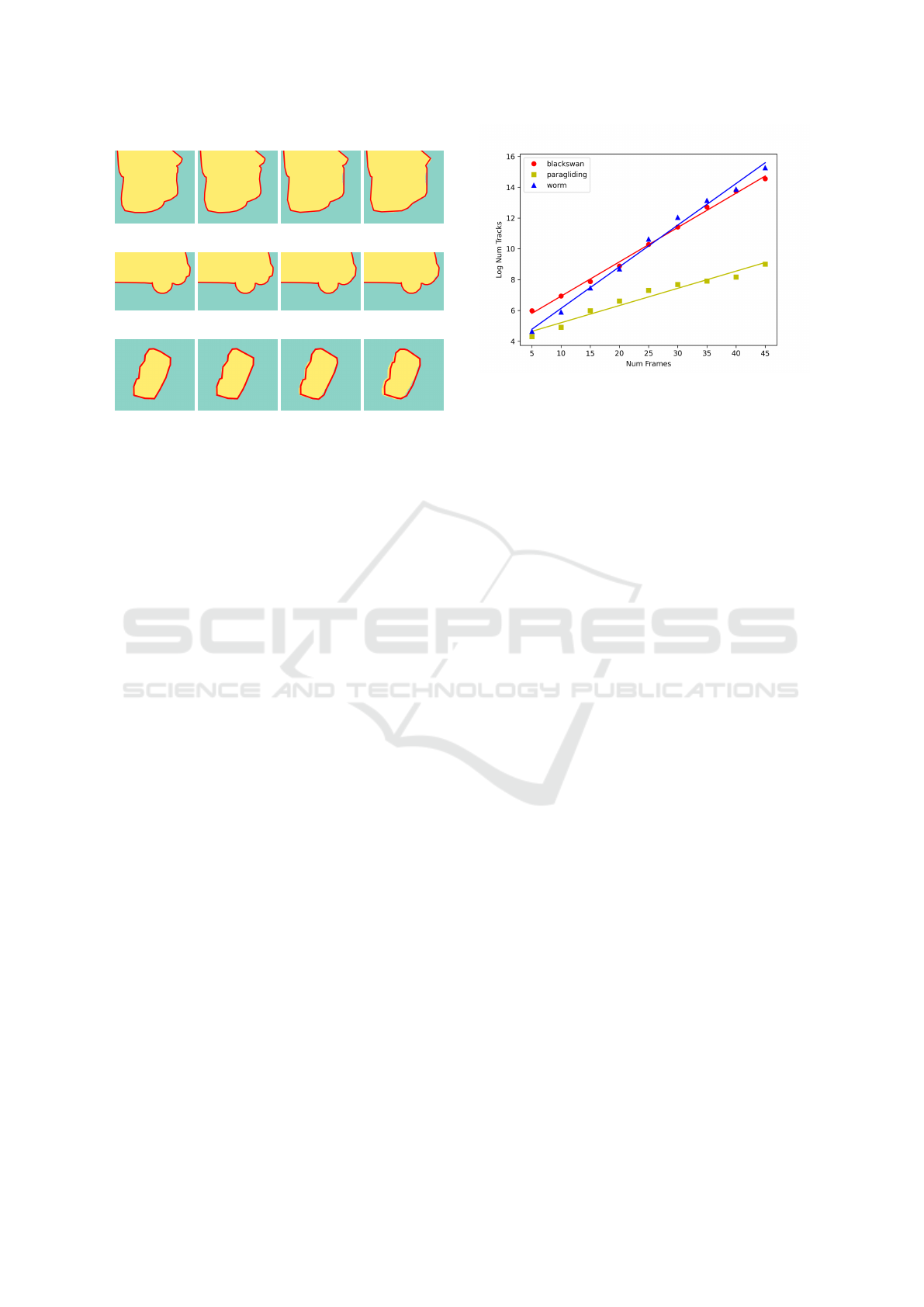
Figure 7: For the “blackswan”, “paragliding” and “worm”
sequences, we restricted the sequence to a given number of
frames and computed the number of animated vertices to
generate during the untangling step. We display the loga-
rithm of that number, along with a linear approximation to
highlight its exponential growth.
and worm. As explained in more details below, these
sequences reached the limits of what can currently be
achieved with Tutrace.
When working on the worm sequence (which is
particularly long), we have found that the impact of
the number of frames is critical for the performance
of the algorithm. Indeed, since the matching step does
not always produce 1-1 correspondences between key
vertices in adjacent frames, some animated vertices
generated at the beginning of the untangling step will
“split” at each new frame, leading to a combinato-
rial explosion. We measured the number of animated
vertices generated until a given frame for several se-
quences in our dataset. The results are shown in Fig-
ure 7. As we can see, the growth can be well approx-
imated by an exponential growth, with a coefficient
that varies from one sequence to another.
As for the cactus sequence, it is part of the syn-
thetic sequences made specifically for these experi-
ments: it consists of a static 3D cactus model around
which the camera is turning. As can be seen in Fig-
ure 8, the particular shape of the cactus will generate
many occlusions, with branches appearing, disappear-
ing and reappearing. Even though the Tutrace algo-
rithm was designed to handle occlusions - such as the
nose on the statue sequence shown in Figure 1 - this
particular case is too complex to untangle for our sys-
tem: when a side branch merges into the central trunk,
the empty region between that branch and the trunk
shrinks and disappears quickly, however the particu-
lar elongated shape of that region makes it difficult for
vertices to get matched properly as they will end up
matching against the outer side of the branch instead,
thus creating erroneous animated vertices. Note that
in practice, rotoscoping artists would not work on the
GRAPP 2025 - 20th International Conference on Computer Graphics Theory and Applications
26

Figure 8: A failure case with the “cactus” sequence.
whole cactus shape at once: they would work on each
branch separately to tackle this occlusion problem.
9 FUTURE WORK
As mentioned previously, an important limitation of
our method is performance, mostly due to the num-
ber of animated vertices that we generate during the
untangling step which can increase quickly with the
number of frames. We see two main ways to over-
come this issue in the future: modify the untangling
algorithm to generate only the necessary animated
vertices and/or cut down the input video into smaller
chunks which will be processed independently and
then merged.
We could also try to reinterpret the untangling
problem as a multi-graph matching task, where the
graphs to match would simply be the key cycles. In-
deed, many advancements have been made in recent
years on this topic (Yan et al., 2016), which would al-
low us to solve the untangling step much faster and
without requiring an ad-hoc method. However such
algorithms are designed to extract collections of cor-
responding nodes in the input graphs, which can be
interpreted in our setting as animated vertices, but not
the structure relating these collections to each other,
i.e. the circular structure of an animated cycle in our
case. Further work would therefore be required to see
if we could extend a multi-graph matching method to
fit our purposes.
Another important topic to investigate is smooth-
ing. Indeed, the shape we currently generate only
contains straight line segments, whereas most image
vectorization methods produce smooth shapes, using
for instance B
´
ezier segments. Smoothing an animated
vector shape is not a trivial problem, however it would
also have another positive side effect: fewer vertices
would be required to accurately vectorize curved ar-
eas in the input images. (Shao and Zhou, 1996) pro-
poses a curve fitting algorithm that could potentially
fit our purposes, if we could properly adapt the iden-
tification of critical points to animated vertices.
It can also be noted that in our pipeline the images
are only fed into the first step, and never used again.
Re-using the input images later in the process could
allow us to improve the quality of the animated shape
by fitting its geometry to the input data. Some meth-
ods for optimizing the rasterization error of a vector
shape have been proposed, such as (Li et al., 2020),
which could be extended to include the temporal di-
mension of video vectorization.
Handling multiple objects and occlusions could
also have a major impact, as these types of situations
arise frequently in rotoscopy, for instance when sev-
eral characters interact in the scene. Building on the
work of (Zhang et al., 2023) could be an interesting
starting point as they provide a framework for solving
both object tracking and layer decomposition.
10 CONCLUSION
We have presented a video vectorization algorithm
that works on a binarized input and generates an an-
imated vector shape. The core of our method lies in
the untangling step, which extracts animated vertices
from static shapes and correspondences between their
vertices. We showed that the output quality is com-
parable to frame-by-frame vectorization, with the ad-
vantage of being directly ready to import and edit in
a DCC. Additionally, the user can control the com-
plexity of the animated shape, thus allowing to create
simpler shapes. We hope that this method, with the
flexible multi-step approach it uses, will serve as a
basis for further development in this area, mostly tar-
geting use cases in rotoscopy for VFX.
ACKNOWLEDGEMENTS
Many thanks to Vincent Demoulin for his useful com-
ments and feedback on both Tutrace and this article.
We also thank the anonymous reviewers for helping
us improve this paper. This work was partially sup-
ported by Technicolor Group.
REFERENCES
Besl, P. J. and McKay, N. D. (1992). Method for regis-
tration of 3-d shapes. In Sensor fusion IV: control
paradigms and data structures, volume 1611, pages
586–606. Spie.
Tutrace: Editable Animated Vector Shape from Video
27

Dalstein, B., Ronfard, R., and Van De Panne, M. (2015).
Vector graphics animation with time-varying topol-
ogy. ACM Transactions on Graphics (TOG), 34(4):1–
12.
Douglas, D. H. and Peucker, T. K. (1973). Algorithms for
the reduction of the number of points required to rep-
resent a digitized line or its caricature. Cartographica:
the international journal for geographic information
and geovisualization, 10(2):112–122.
Favreau, J.-D., Lafarge, F., and Bousseau, A. (2016). Fi-
delity vs. simplicity: a global approach to line drawing
vectorization. ACM Transactions on Graphics (TOG),
35(4):1–10.
Garland, M. and Heckbert, P. S. (1997). Surface simpli-
fication using quadric error metrics. In Proceedings
of the 24th annual conference on Computer graphics
and interactive techniques, pages 209–216.
Kopf, J. and Lischinski, D. (2011). Depixelizing pixel art.
In ACM SIGGRAPH 2011 papers, pages 1–8.
Li, F., Kim, T., Humayun, A., Tsai, D., and Rehg, J. M.
(2013). Video segmentation by tracking many figure-
ground segments. In Proceedings of the IEEE Interna-
tional Conference on Computer Vision, pages 2192–
2199.
Li, T.-M., Luk
´
a
ˇ
c, M., Gharbi, M., and Ragan-Kelley, J.
(2020). Differentiable vector graphics rasterization for
editing and learning. ACM Transactions on Graphics
(TOG), 39(6):1–15.
Li, Y., Wang, C., Hong, J., Zhu, J., Guo, J., Wang, J., Guo,
Y., and Wang, W. (2021). Video vectorization via
bipartite diffusion curves propagation and optimiza-
tion. IEEE Transactions on Visualization and Com-
puter Graphics, 28(9):3265–3276.
Myronenko, A. and Song, X. (2010). Point set registra-
tion: Coherent point drift. IEEE Transactions on Pat-
tern Analysis and Machine Intelligence, 32(12):2262–
2275.
Orzan, A., Bousseau, A., Winnem
¨
oller, H., Barla, P., Thol-
lot, J., and Salesin, D. (2008). Diffusion curves: a vec-
tor representation for smooth-shaded images. ACM
Transactions on Graphics (TOG), 27(3):1–8.
Pont-Tuset, J., Perazzi, F., Caelles, S., Arbel
´
aez, P.,
Sorkine-Hornung, A., and Van Gool, L. (2017). The
2017 davis challenge on video object segmentation.
arXiv preprint arXiv:1704.00675.
Pun, S. and Tsang, C. (2020). Vtracer. https://www.
visioncortex.org/vtracer-docs.
Selinger, P. (2003). Potrace: a polygon-based tracing algo-
rithm.
Shao, L. and Zhou, H. (1996). Curve fitting with bezier
cubics. Graphical models and image processing,
58(3):223–232.
Sun, J., Liang, L., Wen, F., and Shum, H.-Y. (2007). Image
vectorization using optimized gradient meshes. ACM
Transactions on Graphics (TOG), 26(3):11–es.
Vital, L. (2024). Tutrace evaluation videos. {https://doi.org/
10.5281/zenodo.14510189}.
Wang, C., Zhu, J., Guo, Y., and Wang, W. (2017). Video
vectorization via tetrahedral remeshing. IEEE Trans-
actions on Image Processing, 26(4):1833–1844.
Xia, T., Liao, B., and Yu, Y. (2009). Patch-based im-
age vectorization with automatic curvilinear feature
alignment. ACM Transactions on Graphics (TOG),
28(5):1–10.
Yan, J., Yin, X.-C., Lin, W., Deng, C., Zha, H., and Yang,
X. (2016). A short survey of recent advances in graph
matching. In Proceedings of the 2016 ACM on Inter-
national Conference on Multimedia Retrieval, pages
167–174.
Yao, R., Lin, G., Xia, S., Zhao, J., and Zhou, Y. (2020).
Video object segmentation and tracking: A survey.
ACM Transactions on Intelligent Systems and Tech-
nology (TIST), 11(4):1–47.
Yu, Y., Wang, C., Fu, Q., Kou, R., Huang, F., Yang, B.,
Yang, T., and Gao, M. (2023). Techniques and chal-
lenges of image segmentation: A review. Electronics,
12(5):1199.
Zhang, S., Ma, J., Wu, J., Ritchie, D., and Agrawala, M.
(2023). Editing motion graphics video via motion vec-
torization and transformation. ACM Transactions on
Graphics (TOG), 42(6):1–13.
Zhang, S.-H., Chen, T., Zhang, Y.-F., Hu, S.-M., and Mar-
tin, R. R. (2009). Vectorizing cartoon animations.
IEEE Transactions on Visualization and Computer
Graphics, 15(4):618–629.
GRAPP 2025 - 20th International Conference on Computer Graphics Theory and Applications
28
