
A Targeting Attack by Dynamic Fake QR Code Using Invisible Laser
Irradiation
Dai Itakura, Taiga Manabe, Yuki Kamata, Ayana Oku, Hiroshi Yamamoto, Yoshihisa Takayama and
Toshihiro Ohigashi
Tokai University, 2–3–23 Takanawa, Minato-ku, Tokyo, 108-8619, Japan
Keywords:
QR Code, Fake QR Code, Laser.
Abstract:
In this study, we propose a method to generate a fake QR code that can lead to a malicious website at any
particular time by laser irradiation of a QR code. First, we explain the fake QR code. Subsequently, we
will examine the configuration of a fake QR code that dynamically changes the probability of induction to a
malicious website by laser irradiation, considering that the camera treats the area as a bright area when the
area is imaged with high illumination by the laser. We show its feasibility by experimentation. We focus
on the attackable distance, which is critical in evaluating the threat level. The feasibility is then shown and
the threat level is evaluated by the attackable distance. Specifically, we examine the conditions necessary to
achieve long laser irradiation distances. Consequently, a demonstration experiment shows that it is possible
to fake a QR code by laser irradiation over a long distance of approximately 100 meters. Finally, we discuss
countermeasures against laser irradiation for fake operation.
1 INTRODUCTION
QR code (QRc, 2015) is a matrix-type two-
dimensional barcode developed by DENSO WAVE
INCORPORATED in 1994, and an international stan-
dard in ISO. QR codes can handle more data than one-
dimensional barcodes. With the spread of cell phones
and smartphones, they are widely used as a means of
communicating information, such as accessing web-
sites and making payments. Humans do not imme-
diately understand the data content of the displayed
QR code. There are attacks that utilize this fact. One
attack on QR codes was to put a sticker of malicious
QR code on top of the legitimate QR code (Tech in
Asia, 2021).
In a previous study, a fake QR code was found
as an attack against QR codes (Takita et al., 2018).
The method of its composition is shown. Fake QR
codes generate a code that is intermediate between
QR codes corresponding to two URLs. It allows a
black-and-white detection error in a particular module
to cause the decoded URL to switch. Specifically, it
adds a small white or black stain in the center of a par-
ticular module. This probabilistically induces a black-
and-white detection error by the camera, leading the
user to the wrong URL. Countermeasure methods for
fake QR codes are discussed in Reference (Ohigashi
et al., 2021)(Takita et al., 2018). However, software
with the countermeasures is not widely available at
this time. Therefore, it is important to analyze the
attack capability of fake QR codes in environments
where no countermeasures have been implemented.
Additionally, it is important to discuss countermea-
sures against such attacks.
Because the fake QR codes are printed and posted
on a smudged state, the probability of being misdi-
rected after posting is fixed. Consider the case where
the inducement probability is sufficiently low to pre-
vent the user realizing that the posted QR code is a
fake QR code. In this case, the victim of the fake QR
code is unspecified users with low probability. There-
fore, it is difficult to provide fake inducement to a par-
ticular user with a high probability. We call fake in-
ducement the case that we are unintentionally induced
to another website instead of the legitimate website.
In this study, we discuss a method to increase the
probability of inducement on printed materials. Al-
though unrelated to discussion in this paper, one way
to increase the probability of fake inducement is to
replace the QR code displayed on the digital signage
(electronic signage) with a fake QR code. Attacks us-
ing electronic media are expected to be alerted. How-
ever, printed paper does not change the information
written in front of people eyes. Therefore, when read-
Itakura, D., Manabe, T., Kamata, Y., Oku, A., Yamamoto, H., Takayama, Y. and Ohigashi, T.
A Targeting Attack by Dynamic Fake QR Code Using Invisible Laser Irradiation.
DOI: 10.5220/0013102500003899
In Proceedings of the 11th International Conference on Information Systems Security and Privacy (ICISSP 2025) - Volume 2, pages 455-462
ISBN: 978-989-758-735-1; ISSN: 2184-4356
Copyright © 2025 by Paper published under CC license (CC BY-NC-ND 4.0)
455

ing a QR code, one is not expected to be attentive.
In this paper, we propose a dynamic fake QR code
that utilizes the technology of fake QR codes and
laser beams. This QR code can be directed to a ma-
licious website at any time using an invisible laser
beam against a printed static QR code. Specifically,
a laser beam is used to dynamically manipulate the
module’s black-white or white decision. The laser
beam is highly directional, thus it can irradiate a spe-
cific module at a distance from the QR code. This
attack of features is difficult to detect. Therefore, it is
difficult to detect a fake QR code when the attack has
stopped.
The proposed method is a highly covert method
that allows fake inducement of specific targets. A
laser beam with a uniform wavelength and wavefront
is highly directional. This feature allows the beam
to be focused to a specific location. This technology
is applied to various technologies, such as satellite-
based long-distance communication, measurement,
ranging, and power supply (Degnan, 1985)(Hemani
and Georges, 2017)(Jin and Zhou, 2019)(Liu et al.,
2019)(Mohammad and Murat, 2014). Areas that are
highly illuminated by the laser beam are treated as
bright areas when read by the camera. The image
sensors in smartphones and other devices are more
sensitive to a wider range of wavelengths than the hu-
man visible spectrum. Therefore, the user cannot see
directly owing to the wavelength of the laser beam
that illuminates the manipulated object. However,
the camera can be made to recognize it as a bright
area. The QR code can be falsified without noticeable
changes. Furthermore, the fake induction probability
owing to laser irradiation depends on the power of the
laser beam. Therefore, the probability of induction
by a fake operation can be dynamically controlled at
arbitrary timings.
We demonstrate the feasibility of the attack by ex-
periments to target a fake QR code at a distance of 5
m. In the experiments, we change several parameters,
which are the wavelength and the power of the laser,
diameter of irradiation range, and angle of the scan-
ning camera. In addition, to evaluate the covertness
of an attack, it is essential to make an evaluation re-
garding the limits of the distance at which the attack
is successful. Therefore, we verify the conditions for
long-distance fake operation of dynamically fake QR
codes using invisible lasers. Furthermore, demonstra-
tion experiments show the feasibility of long-distance
fake operations. In optical communications, the re-
ceiver has a mechanism to compensate for the propa-
gation angle of the arriving light. However, the pro-
posed method requires precise control of the irradia-
tion angle of the laser beam only by operation on the
transmitter side. When irradiating a QR code module,
if an adjacent unrelated black module is irradiated, the
module is determined to be white and the attack fails.
In particular, precise irradiation that does not affect
the surroundings is necessary. Therefore, we calcu-
late the starting position of the laser beam to ensure
that the laser beam is focused on the QR code. It is
shown that stable irradiation can be achieved by cal-
culating the lens distance. Consequently, a fake op-
eration at a distance of up to 100 m was achieved in
the demonstration test. The results of this experiment
suggest that it may be possible to attack the target QR
code from a neighboring building. Therefore, we con-
sider this experiment a realistic threat as a laser-based
attack. Note that the QR code to be attacked must be
created by the attacker.
Recent studies on the effects of laser irradiation
on security include the Light Commands(Sugawara
et al., 2020), which enable silent voice input by ir-
radiating smart speakers with lasers, and an attack
that misleads the traffic sign recognition system of
self-driving cars by irradiating traffic signs with in-
visible light lasers(Sato et al., 2023). The discussion
on attacks by laser irradiation is one of the important
themes that spills over into these studies.
The structure of this paper is as follows: Section
2 explains the fake QR code on which this research
is based. Section 3 explains the principles of dy-
namic fake QR codes and experiments with varying
parameters. Section 4 calculates the distance between
the laser end-face and the lens that focuses on the
QR code, and based on the results, conducts exper-
iments on irradiation from long distances. Section 5
describes considerations and countermeasures this at-
tack. Section 6 summarizes this paper.
2 FAKE QR CODE
Takita et al. show how QR codes that induce de-
coding errors (fake QR codes) can probabilistically
lead to malicious websites (Takita et al., 2018). Fake
QR codes utilize error-correcting code technology.
As shown in Fig. 1, probabilistically different in-
formation is read. In addition, the probability of
being directed to each website can be adjusted ar-
bitrarily. Therefore, it is possible to make it diffi-
cult to detect the posting of QR codes that are caus-
ing damage by adjusting the system to ensure that
inducements to malicious websites occur rarely. In
this paper, we use the legitimate website (URL1):
http://www.u-tokai.ac.jp/ and the malicious website
(URL2): http://www.u-yokai.ac.jp/. We outline a
method of constructing a fake QR code that proba-
ICISSP 2025 - 11th International Conference on Information Systems Security and Privacy
456
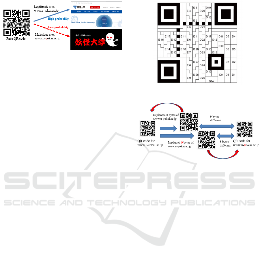
Figure 1: Original Fake QR code.
bilistically generates a lead to these two websites, as
an example.
QR codes embed information by arranging the
smallest unit cell called a module, which indicates one
bit of information, in two dimensions. The informa-
tion is read as an image and decoded. The number
of modules that can be deployed can be specified by
the version information. QR codes use an error cor-
rection code, thus they can be read even if they are
slightly dirty. The error correction level is specified
as L, M, Q, H and S. The QR code used in this paper
is the 2-M type QR code shown in Fig. 2. D1–D28
are the data part and E1–E16 are the error-correction
part. Error correction can restore incorrect data from
up to 8 symbols (8 bytes) of this QR code.
We show how to create a fake QR code that prob-
abilistically directs the user to URL1 or URL2. First,
we create two QR codes that are similar. The 2-M
type QR code can correct errors up to 8 symbols.
Therefore, these two similar QR codes must differ by
at least 2 × 8 + 1 = 17 symbols. Subsequently, we
create a QR code that combines symbols from both
QR codes and resembles both, as shown in Fig. 3.
This can be achieved by overwriting different parts
of each QR code on a symbol-by-symbol basis. The
created QR code can be restored to another QR code
by overwriting one additional symbol. However, the
symbol difference between URL1 and URL2 is only
one module. Therefore, inverting the black and white
of one module changes the URL to be read. Finally,
we change the color of the central part of the module
to ensure that this one module is probabilistically de-
termined to be white or black. Changing the color of
the central part of the module, rather than the entire
module, makes loading unstable. This induces prob-
abilistic reading errors. The probability depends on
the brightness of the center, camera to be read, OS
performance, and QR code. It does not appear to be a
significant threat immediately owing to the difficulty
of controlling the probability.
Figure 2: Module location in a 2-M type QR code.
Figure 3: Creating an intermediate QR code.
3 DYNAMIC FAKE QR CODE
3.1 Principle
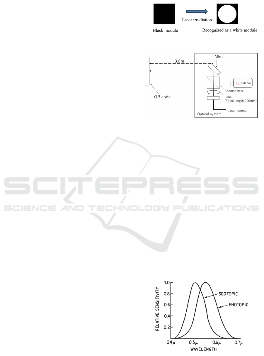
In this section, we explain dynamic fake QR codes. A
dynamic fake QR code has a similar structure to the
fake QR code in Chapter 2. The difference between
the two QR codes is whether or not there is a mod-
ule that changes probabilistically. Dynamic fake QR
codes do not have a module that changes probabilisti-
cally. However, this QR code becomes different from
the original by irradiating a laser beam on a specific
black module. This QR code is realized by laser ir-
radiation of a specific black module. By irradiating
the laser, the camera recognizes the black module as
a white module like Fig. 4. Consequently, the cam-
era reads a different URL from the original QR code.
This allows fake operations to be performed from a
distance only when the laser beam is irradiated.
3.2 Experiments with Variable
Parameters
We conducted an experiment in which we irradiated
a laser beam with a QR code and directed the user to
A Targeting Attack by Dynamic Fake QR Code Using Invisible Laser Irradiation
457
a different URL from the original one to demonstrate
the feasibility of the attack. In this experiment, the
angle of scans and the power of the laser are changed.
This experiment allowed us to intentionally change
the reading results by irradiating the laser.
The whole system of the experiment is shown in
Fig. 5. The distance between the optical system that
controls the pointing of the laser beam and the QR
code is approximately 3.8 m. The wavelengths of the
laser beam used in the experiments were 635 nm and
785 nm, respectively. The range of wavelengths visi-
ble to the human eye varies between individuals, with
the minimum being 360–400 nm and the maximum
being 760–830 nm. Cameras, such as those of smart-
phones can be sensitive to ultraviolet rays below 400
nm, which is shorter than visible light, and infrared
rays above 780 nm. The sensitivity regions are shown
in Fig. 6 and Fig. 7 (Lucid Vision Labs, 2024)(Smith,
2000). The length of one side of the QR code is 114
mm, the length of one piece of the module is 4 mm,
and the focal length of the lens is 40 mm. Illumina-
tion power of 2.65 mW and 9.4 mW are used at 635
nm wavelength. Illumination power of 2.65 mW and
7.1 mW are used at 785 nm wavelength. However,
the illumination power at 785 nm could not be strong
owing to equipment failure. Irradiation range diame-
ter is 2 mm and 4 mm. The angles of scanning are 45°
and 90°. The 90° is the one where the paper surface
of the QR code and the camera are facing each other.
We used a QR code that leads the user to URL2 when
the QR code was read without any fake operation, and
leads the user to URL1 when the QR code was read
with a fake operation. The camera of iPhone was used
to read the QR code. Experiments were conducted
by changing the power of the laser beam, irradiation
range, and irradiation angle of the laser beam relative
to the normal of the printed surface of the QR code.
The wavelengths for Experiments 1 and 2 were 635
nm and 785 nm, respectively.
The results of the experiments are shown in Table
1 and Table 2. The URL1 or URL2 indicates that the
result switches depending on the timing of the scan.
URL2 was read when the illumination power was 2.65
mW with a 635 nm laser beam. When the illumina-
tion power was 9.4 mW, two URLs were read from an
angle of 45
◦
, switching between them at high speed.
From a 90
◦
angle, URL1 was read. The camera may
not be able to recognize the light when the power is
weak or when it is at an angle to the illuminated sur-
face. URL1 was read at any power, angle, and irradi-
ation range for the 785 nm laser beam. However, in
the angled case, the two URLs were read alternately.
It is believed that the camera does not recognize the
bright area owing to the reflection of the laser light on
Figure 4: Laser irradiation on the module.
Figure 5: Full system of experiments.
the irradiated surface irradiating at an angle. Specif-
ically, this also indicates that it is possible to attack
and that a probabilistic attack is possible. Fig. 8 and
Fig. 9 show photographs of a normal QR code and a
QR code irradiated with laser beam.
4 CHALLENGE TO
LONG-DISTANCE ATTACK
As in the experiment in Section 3, irradiation from
a short distance is more likely to be found attack-
ing. Therefore, it is necessary to attack from an un-
detectable location. For the practical attack, the at-
tack should be extended to long distance attack, e.g.
50 m or 100 m. Subsequently, the attack may work
against the target fake QR code posted on a neighbor-
ing building or over a street. However, to irradiate a
laser beam from a long distance, it is necessary to fo-
cus the laser beam. In this section, we calculate the
Figure 6: Photopic luminous efficiency function (Smith,
2000).
ICISSP 2025 - 11th International Conference on Information Systems Security and Privacy
458
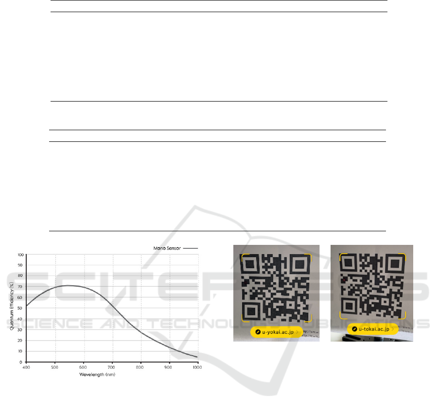
Table 1: Results of Experiment 1.
Illumination power Irradiation range diameter Camera angle Result of URLs
2.65 mW 2 mm 45
◦
URL2
2.65 mW 2 mm 90
◦
URL2
2.65 mW 4 mm 45
◦
URL2
2.65 mW 4 mm 90
◦
URL1
9.4 mW 2 mm 45
◦
URL1 or URL2
9.4 mW 2 mm 90
◦
URL1
9.4 mW 4 mm 45
◦
URL1 or URL2
9.4 mW 4 mm 90
◦
URL1
Table 2: Results of Experiment 2.
Illumination power Irradiation range diameter Camera angle Result of URLs
2.65 mW 2 mm 45
◦
URL1 or URL2
2.65 mW 2 mm 90
◦
URL1
2.65 mW 4 mm 45
◦
URL1 or URL2
2.65 mW 4 mm 90
◦
URL1
7.1 mW 2 mm 45
◦
URL1 or URL2
7.1 mW 2 mm 90
◦
URL1
7.1 mW 4 mm 45
◦
URL1
7.1 mW 4 mm 90
◦
URL1
Figure 7: Quantum efficiency of a typical camera (Lucid
Vision Labs, 2024).
emission position and focal point of the laser beam at
the imaging lens. Based on the results, we conduct
long-distance irradiation experiments.
4.1 Image Formation Position of Thin
Lens
In Section 3.2, laser irradiation was used to fake the
QR code at a distance of approximately 3.8 m. The
QR code module used in this experiment was sized
to fit the light flux diameter of the collimated beam.
However, to fake the QR code by irradiating it from
a greater distance, it is necessary to focus the laser
beam. Therefore, in this section, the emission posi-
tion and focal point of the laser beam at the imaging
Figure 8: Normal QR
code.
Figure 9: Wavelength 635
nm (irradiation range 2
mm, illumination power
7.1 mW).
lens are calculated for long-distance fake operation.
For a thin lens, let b be the position of the image
by the lens of the light emitted from a on the optical
axis. The lens imaging equation is shown in Eq. (1)
(Hecht, 2017).
a
−1
+ b
−1
= f
−1
(1)
The position of the image formed by the thin lens is
shown in Fig. 10. Where a is the distance from the
main plane of the lens to the QR code, b is the dis-
tance from the main plane of the lens to the position
of the laser beam, and f is the focal length of the lens.
Assuming the focal length to be 200 mm, from Eq.
(1), the value of b for a is shown in Fig. 11.
Based on these results, we irradiated QR codes us-
ing invisible lasers.
A Targeting Attack by Dynamic Fake QR Code Using Invisible Laser Irradiation
459
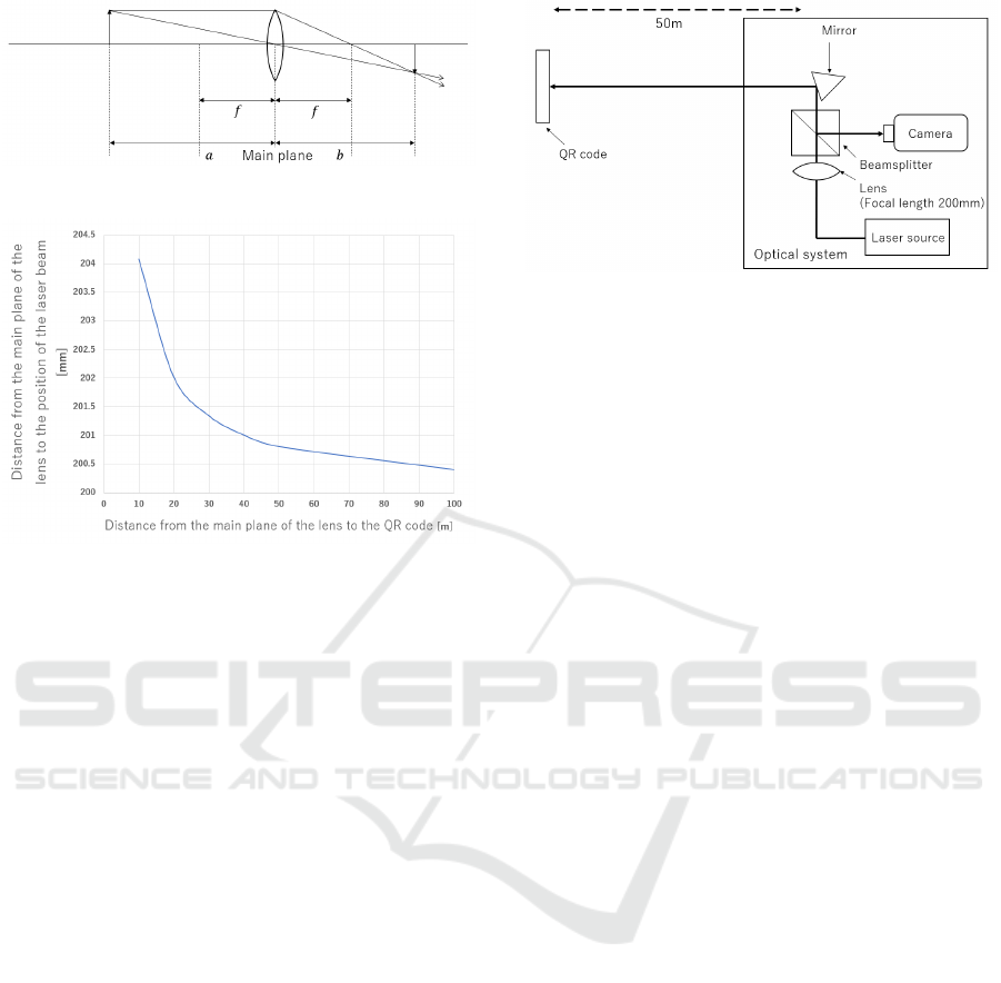
Figure 10: Image formation by a single thin lens.
Figure 11: Relation between laser beam emission position
and image formation position.
4.2 Long-Distance Irradiation
Experiment
In this section, we conducted an experiment in which
we irradiated a QR code with a laser beam from a
distance of 10 to 100 meters to direct users to a URL
that is different from the original URL. Consequently,
we confirmed the difference in the destination of the
guided directions of the fake QR code depending on
the distance.
A diagram of the experiment at 10–50 meters is
shown in Fig. 12; a diagram of the experiment at 100
m in Fig. 13; and a simplified diagram of the exper-
imental environment in Fig. 14. The distances be-
tween the optics that control the pointing of the laser
beam and the QR code are 10, 20, 30, 40, 50, and
100 meters, respectively. In the 100 m experiment, a
mirror is set up at 50 m and the laser beam is folded
back. Fig. 14 shows a plan view of the experimental
site, with the air conditioning vents located between
40 and 50 meters. The wavelengths of the laser beam
used in the experiments were 635 nm and 785 nm, re-
spectively. The power of the laser beam was measured
at the position where the laser beam was irradiated.
The value was approximately 10 mW. The length of
one side of the QR code used was 114 mm, as in Sec-
tion 3.2, and the length of a piece of the module was
4 mm. Scanning a QR code is performed with the pa-
per side of the QR code and the camera facing each
other in front of the camera. Light emitted from the
Figure 12: Configuration diagram of the 10–50 meters ex-
periment.
laser source of the optical system is guided through
a single-mode fiber and emitted into space. The fo-
cal point can be adjusted by passing the laser beam
through a lens. In the experiments, the distance from
the single fiber to the lens was adjusted based on Fig.
10. Additionally, a beam splitter was employed to ad-
just the laser beam to the desired location by adjusting
the mirror while inspecting it through a camera.
Let URL1 be the URL where the QR code is read
without laser irradiation, and let URL2 be the URL
where the QR code is faked by laser irradiation.
The results of the experiment are shown in Table
3. URL2 was read by laser irradiation at 10, 20, 30,
and 40 meters for both 635 and 785 nm. In the ex-
periments at 50 and 100 meters, URLs 1 and 2 were
read alternately. One possible reason for this result
is that the irradiation position of the laser beam on
the QR code was fluctuating. In this experimental en-
vironment, the laser beam was blurred owing to at-
mospheric turbulence caused by the air conditioning.
This may have caused the irradiated area to vary by
2 to 3 mm vertically and horizontally, resulting in a
difference in the URL readout.
During the demonstration experiment, fake induc-
tion succeeded even when the laser beam spread be-
yond the size of the module. This is because the inten-
sity of the laser beam decreases as it moves outward
from the center of the laser beam. The outward spread
of the light decreases in intensity. Therefore, even if
the laser beam irradiated beyond the size of the mod-
ule, only the center portion is considered to have been
determined as the bright area. Therefore, it is impor-
tant to note that the range of possible irradiation is not
the apparent range of the laser beam, but the range of
high optical intensity.
ICISSP 2025 - 11th International Conference on Information Systems Security and Privacy
460
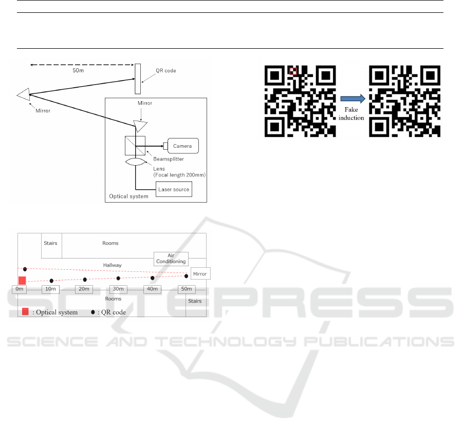
Table 3: Experimental results when irradiated with 635 nm and 785 nm wavelength.
Distance from the main plane of the lens to the QR code.
10m 20m 30m 40m 50m 100m
Wavelength of laser beam
635 nm URL2 URL2 URL2 URL2 URL1 or 2 URL1 or 2
785 nm URL2 URL2 URL2 URL2 URL2 URL1 or 2
Figure 13: Configuration diagram of the 100 m experiment.
Figure 14: Simplified diagram of the experimental environ-
ment.
5 CONSIDERATIONS
5.1 Fake QR Codes Suitable for
Long-Distance
This section discusses fake QR codes suitable for
long-distance attacks. In the discussion up to the pre-
vious section, long-distance attack was achieved by
calculating the emission position and focal point of
the laser beam at the imaging lens. When consider-
ing the ease of focusing, it is considered effective to
widen the target area of laser irradiation (laser aper-
ture). This is because it eases the attack and the lim-
itation of the equipment to be used. Therefore, we
consider fake QR codes that have a wide range of irra-
diation targets, such as 2×2 or 3×3 modules, instead
of one module.
The laser irradiation changes the judgment in the
direction from black to white. We focus on this
change and the fact that the judgment remains white
even when a white module is irradiated by laser. For
Figure 15: Fake QR code with expanded attack range (2 ×
2).
example, if the entire area of a 2×2 modules is white
to produce fake induction, the aperture can be in-
creased by a factor of approximately 2. Thus, if it
is possible to make the QR code in which all areas
larger than 2×2 modules can be white, the rectangle
of laser irradiation can be made larger.
However, it is not always possible to obtain a QR
Code that satisfies these conditions. According to
Reference (Ohigashi et al., 2021), the QR Code pat-
tern can be extended by using the parameters of the
HTTP GET method. Specifically, this method con-
siders some cases, in which adding an arbitrary string
after “?” in the URL will access the same website as if
the parameter had not been added. The cases here are
static pages or dynamic pages with no corresponding
parameters. The same effect can be achieved by using
the HTML fragment identifier “#”. We introduce this
method. We searched heuristically with this method
and found a QR code that can be attacked within a
2×2 range, as shown in Fig. 15. The area circled in
red on the left side of the QR code in Fig. 15 indicates
the area that can be laser irradiated for fake induction.
5.2 Countermeasures
As a countermeasure against static, fake QR codes,
Takita et al. have shown how to change the QR code
reading application (QRc, 2015). Specifically, mul-
tiple readings are attempted using a decoder, and the
output results are compared. Dynamic fake QR codes
can lead the user to another site with a high probabil-
ity, such as probability 1, during an attack. The coun-
termeasures taken by Takita et al. cannot prevent this
because the legitimate sites are always accessed once
the laser irradiation is stopped. The countermeasures
taken by Takita et al. cannot prevent this because the
legitimate sites are accessed when the laser irradiation
is stopped.
A Targeting Attack by Dynamic Fake QR Code Using Invisible Laser Irradiation
461

However, Ohigashi et al. propose a detection
method that focuses on the principle of the construc-
tion method of fake QR codes (Ohigashi et al., 2021).
Dynamic fake QR codes have the same characteristics
as static fake QR codes. Thus, The countermeasure
methods in Reference (Ohigashi et al., 2021) work ef-
fectively. Dynamic fake QR codes require the irradia-
tion of a laser. Therefore, an effective countermeasure
can be achieved by adding atmospheric effects to the
laser beam. Specifically, it is considered effective to
install air conditioning, etc.
6 CONCLUSION
In this study, we proposed a method to generate a fake
QR code that can lead to a malicious site at arbitrary
timing by irradiating a laser beam onto a QR code.
Specifically, we considered that certain modules are
treated as bright areas when they are read by a cam-
era with laser irradiation. In addition, a study was
conducted on faking from long distances using laser
irradiation. Calculations showed the relationship of
the emission position to focus on the QR code. Sub-
sequently, experiments were conducted to confirm the
operation of QR code fake by laser irradiation at 10,
20, 30, 40, and 50 meters. In this experimental en-
vironment, the URL before the fake operation was
occasionally loaded at a distance of 50 or 100 me-
ters. The cause is owing to be that the air-conditioning
system was in operation. The air conditioning sys-
tem was centrally controlled and could not be shut
down for the experiments. The air conditioning may
have caused fluctuations in the atmosphere, making
it difficult for the laser beam to continue irradiating
the target module. Future experiments conducted over
longer distances, such as 1 km, will require more pre-
cise laser irradiation. It is necessary to study the ef-
fect of long-distance laser irradiation, which is sub-
ject to strong atmospheric fluctuations, on the fake
operation. Furthermore, we confirmed that the results
change with the angle of the reading, even at the same
laser power. In future work, we will study the change
of the inducing site with the angle of the reading rel-
ative to the laser irradiation.
ACKNOWLEDGEMENTS
This work was supported in part by the JSPS KAK-
ENHI JP24K14952.
REFERENCES
(2015). Information technology, Automatic Identification
and data capture techniques - QR Code bar code sym-
bology specification.
Degnan, J. J. (1985). Satellite laser ranging: Current sta-
tus and future prospects. IEEE Transactions on Geo-
science and Remote Sensing, GE-23(4):398–413.
Hecht, E. (2017). Optics. Pearson Education Inc., Essex,
5th edition.
Hemani, K. and Georges, K. (2017). Optical commu-
nication in space: Challenges and mitigation tech-
niques. IEEE Communications Surveys & Tutorials,
19(1):57–96.
Jin, K. and Zhou, W. (2019). Wireless laser power transmis-
sion: A review of recent progress. IEEE Transactions
on Power Electronics, 34(4):3842–3859.
Liu, Z., Barlow, J. F., Chan, P. W., Fung, J. C. H., Li, Y.,
Ren, C., Mak, H. W. L., and Ng, E. (2019). A review
of progress and applications of pulsed doppler wind
lidars. Remote. Sens., 11(21):2522.
Lucid Vision Labs (2024). Understanding digital
image sensors. https://thinklucid.com/tech-briefs/
understanding-digital-image-sensors/. Accessed:
2024-06-13.
Mohammad, A. K. and Murat, U. (2014). Survey on free
space optical communication: A communication the-
ory perspective. IEEE Communications Surveys & Tu-
torials, 16(4):2231–2258. Fourth quarter.
Ohigashi, T., Kawaguchi, S., Kobayashi, K., Kimura, H.,
Suzuki, T., Okabe, D., Ishibashi, T., Yamamoto, H.,
Inui, M., Miyamoto, R., Furukawa, K., and Izu, T.
(2021). Detecting fake QR codes using information
from error-correction. J. Inf. Process., 29:548–558.
Sato, T., Bhupathiraju, S. H. V., Clifford, M., Sugawara,
T., Chen, Q. A., and Rampazzi, S. (2023). Wip: In-
frared laser reflection attack against traffic sign recog-
nition systems. In Proceedings of the Inaugural Sym-
posium on Vehicle Security and Privacy (VehicleSec
2023), page 5 pages.
Smith, W. J. (2000). Modern Optical Engineering. McGraw
Hill Education Inc., New York, 3rd edition.
Sugawara, T., Cyr, B., Rampazzi, S., Genkin, D., and Fu,
K. (2020). Light commands: Laser-based audio injec-
tion on voice-controllable systems. In Proceedings of
the USENIX Security Symposium 2020, pages 2631–
2648.
Takita, M., Okuma, H., and Morii, M. (2018). A construc-
tion of fake QR codes based on error-correcting codes.
In Sixth International Symposium on Computing and
Networking, CANDAR, pages 188–193. IEEE Com-
puter Society.
Tech in Asia (2021). Thieves are pickpocketing wallet apps
in china. Tech in Asia. Accessed: 2021-03-28.
ICISSP 2025 - 11th International Conference on Information Systems Security and Privacy
462
