
Towards Synthesis-Based Engineering for Cyber-Physical Production
Systems
Wytse Oortwijn
1
, Yuri Blankenstein
1,2
, Jos Hegge
1
, Dennis Hendriks
1,3
, Pi
¨
erre van de Laar
1
,
Bram van der Sanden
1
, Laura van Veen
1
and Nan Yang
1
1
TNO-ESI, The Netherlands
2
Capgemini Engineering, The Netherlands
3
Radboud University, The Netherlands
Keywords:
Supervisory Control, Systems Engineering, Synthesis Based Engineering, Model Based Design, Industrial
Adoption.
Abstract:
Supervisory control is a key part of Cyber-Physical Production Systems (CPPSs), to orchestrate all system
resources to work together in a safe, correct, and optimal way. Engineering reliable supervisors for industrial
CPPSs is highly challenging due to their complex nature. Synthesis-Based Engineering (SBE) is an engi-
neering approach centered around supervisory controller synthesis, a technique for automatically computing
correct-by-construction supervisors out of formal system requirements and plant models that describe unre-
stricted system behavior. Even though SBE may lead to higher degrees of automation and faster feedback
cycles, SBE may be difficult to integrate into existing ways of working since it is different from traditional
engineering. This article contributes a three-step approach to gradually introduce SBE in industrial settings.
We are instantiating this approach in a research case together with ASML and VDL-ETG, by developing a
proof-of-principle workflow. In this workflow, control is specified as UML activities, for which we contribute
a formal execution semantics since that is missing in current practice. Moreover, we discuss design assistance
provided in the workflow as well as its evaluation with domain experts. The domain experts see the value of
automated design assistance and are willing to take further steps towards the adoption of SBE.
1 INTRODUCTION
Supervisory control is a key part of Cyber-Physical
Production Systems (CPPSs), which are systems con-
sisting of mechatronic components that comprise the
physical part of a system, and which are coordinated
by control software that comprise the cyber part.
CPPSs evolve over time and are typically not indi-
vidual products, but product lines with many configu-
rations and variations (Linden et al., 2007). Their su-
pervisory controllers should orchestrate all resources
to work together in the right way to ensure safe, cor-
rect, and optimal system behavior.
Engineering reliable supervisory controllers for
industrial CPPSs is challenging due to their complex
nature (Fokkink et al., 2023a). For example, such
systems are typically worked on by multiple engi-
neering teams of various disciplines that must coop-
erate. These teams must engineer supervisory con-
trollers that adhere to many safety and functional re-
quirements, which may be incomplete, could be hard
to realize, and might change over time. The con-
trollers must let the system operate safely, correctly,
and optimally, also in exceptional situations, thereby
considering all configurations and variations for prod-
uct lines as well as potentially high degrees of con-
currency that CPPSs may have. The combination of
all these complexity factors, which moreover tend to
increase further over time due to system evolution,
might make manual engineering infeasible.
One strategy for managing this complexity is em-
ploying Synthesis-Based Engineering (SBE) (Baeten
et al., 2016), which is an engineering approach that
combines model-based engineering with computer-
aided design. SBE is centered around supervisory
controller synthesis (Ramadge and Wonham, 1987;
Wonham et al., 2018), a technique for computing
correct-by-construction controllers from formal plant
models that describe unrestricted system behavior,
and formal system requirements. These formal mod-
158
Oortwijn, W., Blankenstein, Y., Hegge, J., Hendriks, D., Laar, P., van der Sanden, B., Veen, L. and Yang, N.
Towards Synthesis-Based Engineering for Cyber-Physical Production Systems.
DOI: 10.5220/0013103300003896
In Proceedings of the 13th International Conference on Model-Based Software and Systems Engineer ing (MODELSWARD 2025), pages 158-168
ISBN: 978-989-758-729-0; ISSN: 2184-4348
Copyright © 2025 by Paper published under CC license (CC BY-NC-ND 4.0)

els help to manage complexity by their focus on spec-
ifying requirements, i.e., what the system should do
rather than how the controllers should realize them in
every relevant situation. Specifying the how, i.e., the
design, is often significantly more complex than spec-
ifying the what, i.e., requirements
1
. SBE largely auto-
mates the realization of supervisory controllers: they
can automatically be (re)synthesized from the for-
mal specifications in a correct-by-construction fash-
ion. This may lead to higher degrees of automation
and faster feedback cycles in the development pro-
cess (Fokkink et al., 2022; Fokkink et al., 2023b).
Despite these potential benefits, integrating SBE
into existing ways of working is difficult since it dif-
fers from traditional engineering, e.g., by putting a
stronger focus on handling requirements. This article
contributes a three-step approach for gradually intro-
ducing SBE in industrial settings. The first step of this
approach is formalizing the (current) control specifi-
cations, as an enabler for design assistance. A key
aspect of the specification formalism is composition-
ality, the ability to compose larger specifications out
of smaller ones. The second step is introducing design
assistance for validating and verifying specifications,
e.g., by means of simulation and property checking.
This may already lead to less defects and reduced
cost, and puts validation support in place, which is es-
sential in SBE for determining whether the specified
requirements are the right ones. The third step is sup-
porting automated synthesis of these formal control
specifications out of system requirements and plant
models of unrestricted system behavior. The compo-
sitional nature of the formal control specifications al-
lows engineers to synthesize parts of the specification
while still being able to manually specify other parts,
and gradually scale up synthesis as needed. The non-
synthesized parts can then still be verified, to check
their adherence to the specified system requirements.
We are instantiating our three-step approach by
developing a tool-supported workflow, with the aim to
introduce SBE in industrial settings. As a carrier case
for the research, we consider the development pro-
cess of the wafer handler for ASML’s lithography ma-
chines, jointly developed by ASML
2
and VDL-ETG
3
.
The wafer handler is a complex subsystem respon-
sible for transporting wafers between the track and
wafer stage at a specified throughput rate. Eventually,
once this workflow is in place, we aim to investigate
1
A FIFO requirement is an example of an easy-to-
specify yet hard-to-realize requirement, as is showcased
here (Accessed 2024-12-18): https://eclipse.dev/escet/cif/
synthesis-based-engineering/example.html.
2
https://www.asml.com (Accessed 2024-12-18).
3
https://www.vdletg.com (Accessed 2024-12-18).
to what extent SBE can help engineers and architects
that are non-experts in formal methods to manage the
increasing complexity of specifying wafer flow.
Wafer flow is specified in terms of UML activities,
but in an informal way, i.e., in the absence of a formal
definition of what their execution means. Therefore,
addressing step one of the approach, we contribute a
formal execution semantics for these activities, cov-
ering relevant specification concepts that are being
used, in particular atomicity, conditional waiting, and
guards and effects for data handling. To the best of
our knowledge, such concepts are not native in exist-
ing standard definitions of activities like fUML (Ob-
ject Management Group, 2021). That is, these con-
cepts can be expressed in terms of other fUML con-
cepts, but that is cumbersome to specify and not as
intuitive for users.
A first proof-of-principle workflow has been de-
veloped that is centered around these formalized
UML activities. This workflow includes initial design
assistance—step two of the approach—in the form
of modelling, simulation and verification support, by
means of (translations to) off-the-shelf tooling. Sup-
port for synthesis—step three of the approach—is not
yet included. However, the feasibility of synthesizing
UML activities has been demonstrated (Laar, 2023).
We have evaluated our first workflow with engi-
neers and architects from ASML and VDL-ETG, with
positive outcome. They expressed interest in formal-
izing their wafer flow specifications to enable design
assistance and later synthesis, to shorten feedback cy-
cles and help manage the increasing complexity.
To summarize our contributions:
1. We contribute an approach to (gradually) intro-
duce SBE in industrial settings where formal
modelling is not yet common practice.
2. We contribute an execution semantics of UML ac-
tivities. Such a formal semantics is needed as pre-
requisite for applying our approach at ASML and
VDL-ETG.
3. We present first experiences and results with exe-
cuting this approach at ASML and VDL-ETG.
The rest of the article is organized as follows. Sec-
tion 2 gives necessary background on SBE. Section 3
explains the approach towards adopting SBE in in-
dustrial settings. Section 4 discusses the proof-of-
principle workflow that implements our approach.
In particular, we define activities and their execu-
tion semantics as the main specification formalism
(Sec. 4.1), discuss design assistance for these activ-
ities (Sec. 4.2), discuss the evaluation of the work-
flow with architects and engineers from ASML and
VDL-ETG (Sec. 4.3), and outline the high-level strat-
Towards Synthesis-Based Engineering for Cyber-Physical Production Systems
159

egy for extending the workflow with synthesis support
(Sec. 4.4). Finally, Section 5 discusses related work
and Section 6 concludes.
2 SYNTHESIS-BASED
ENGINEERING
Our aim is to gradually introduce SBE of supervisory
control into industrial practices. The supervisory con-
trollers are responsible for orchestrating the individ-
ual system components to work together correctly and
optimally (Sheridan and Johannsen, 1976). We con-
sider supervisors of discrete event systems. That is,
movements of mechanical components are initiated
by discrete outputs from the supervisory controller
(e.g., ‘start’ and ‘stop’) based on discrete inputs from
the system (e.g., sensor observations) although these
movements may themselves be continuous in time.
The SBE approach is centered around supervi-
sory controller synthesis, a technique for automati-
cally computing correct-by-construction supervisory
controllers based on formal specifications of system
requirements and the unrestricted behavior of the
mechanical components. Code generation, e.g., for
PLCs, can then be employed on synthesized con-
trollers (Reijnen, 2020; Reijnen et al., 2022). The
input component specifications for controller synthe-
sis are called plants, and describe all possible unre-
stricted component behavior in terms of events and
indicate which of these are controllable. Supervisors
can only influence controllable events, by disabling
them whenever they would (in)directly cause viola-
tions of requirements. Moreover, synthesized super-
visors are guaranteed to be minimally restrictive: they
do not restrict controllable events more than needed.
Since SBE largely automates the design, realiza-
tion and verification of supervisors, engineers can fo-
cus primarily on specifying and validating the sys-
tem requirements. At the same time this makes SBE
different from traditional engineering, and therefore
non-trivial to integrate into industrial practices. In
traditional engineering, requirements and designs are
typically specified in informal documents, which are
input for software engineers to write code, which in
turn is verified and validated by means of testing.
With Model-Based Engineering (MBE), the design
specifications are formalized as models, from which
code implementations can automatically be gener-
ated. One could additionally formalize the require-
ments, to be able to automatically check them on
the models, leading to the approach of Verification-
Based Engineering (VBE). SBE extends MBE and
takes VBE one step further, by synthesizing the de-
signs from the formal requirements in a correct-by-
construction manner.
3 INCREMENTAL MIGRATION
TO SBE
We contribute a high-level approach for gradually in-
tegrating SBE in industrial ways of working where
(means for) SBE are not yet in place. This approach
is centered around the observation that, in order to
adopt SBE, first MBE and VBE should progressively
be adopted to some extent. This not only enables
SBE, but also gradually scales up the degree of de-
sign automation, thereby allowing users to gradually
get used to formal specifications and think in terms of
requirements (the what) rather than the detailed de-
sign (the how).
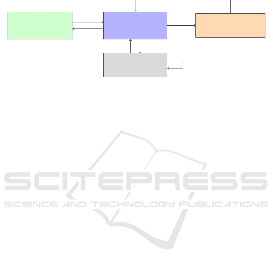
Figure 1 shows the approach (Hegge et al., 2023),
consisting of three steps: (1) formalizing the cur-
rent specifications; (2) providing design assistance for
these formal specifications; and (3) providing support
for synthesizing these specifications.
Step (1). From the starting point of traditional en-
gineering, step (1) is formalizing the current design
specifications into formal models that have a well-
defined unambiguous semantics. Apart from being
essential in enabling design assistance and synthesis,
this step may already provide practical value on itself,
e.g., by requiring engineers to think more critically
about (the meaning of) their specifications. Moreover,
this step enables automatic generation of relevant ar-
tifacts from the models, like code, documentation,
and tests. Generating such artifacts not only reduces
implementation effort, but also ensures that develop-
ments artifacts are consistent with one another. Ar-
tifact generation should however ensure traceability:
whenever an issue occurs during system execution, it
should be possible to link the observed behavior back
to formally specified behavior, to support diagnostics.
To start with step (1), a specification formalism
needs to be defined or chosen. A key property of the
chosen formalism is compositionality: the ability to
compose larger specifications out of smaller ones, for
example by means of hierarchy. Compositional spec-
ifications allow multiple development teams to work
independently on different parts of the overall specifi-
cation. They also simplify the gradual introduction of
SBE, by allowing synthesized control specifications
to be composed with ones that are manually made.
A practical consideration for implementing
step (1), is to stay close to currently-used specifi-
cation languages, even when these are not optimal
MODELSWARD 2025 - 13th International Conference on Model-Based Software and Systems Engineering
160
Formal synthesis
specifications
(e.g., plants, requirements)
Step (3)
Formal control
specifications
(e.g., UML activities)
Step (1)
Design assistance
(e.g., simulation, verification)
Step (2)
Generated artifacts
(e.g., code, documentation)
Synthesize
Link
Analyze
Link
Generate
Execute
Observe
Incorporate feedback
Figure 1: A three-step approach for gradual adoption of SBE. Step (1), formalizing control specifications, is shown in blue.
Step (2), establishing design assistance for formal control specifications, in orange. Step (3), synthesizing control specifica-
tions from synthesis specifications, in green.
for automated analysis and synthesis. Especially in
brownfield situations, switching to a new specifica-
tion formalism would not only require formalizing
the existing specifications, but also converting them
to suit the new formalism, training engineers and
architects to work with this new formalism, adapting
the overall development process accordingly, etc.
Another consideration is to connect to existing in-
dustry standards for modeling, like UML or SysML,
whenever possible. Such industry standards are
accessible for engineers, e.g., due to their widely
available documentation and (community) support
including commercial tooling, while preventing
companies from having to maintain (expertise of)
their own standards and associated tooling.
Step (2). Once formal specifications are in place,
suitable design assistance can be developed for them.
The execution semantics of the formal specifications
enables simulation, and checking of standard prop-
erties like absence of deadlocks. Moreover, a for-
mal semantics allows different validation and verifi-
cation techniques to be consistent with one another,
e.g., any property violation found by a model checker
can be visualized by simulating the counterexample.
Such design assistance helps to find potential prob-
lems early, leading to fewer defects and reduced cost.
It also shortens feedback cycles: architects are able to
validate ideas at design-time, without having to wait
for a concrete code implementation.
One practical consideration for adopting design
assistance is leveraging existing tooling when pos-
sible, to prevent companies from having to de-
velop/maintain in-house technology. For example,
many verifiers come with their own front-end specifi-
cation language, to which the specifications of step (1)
may be translated in a behavior-preserving manner.
Step (3). The next step towards migrating to SBE
is introducing support for synthesizing formal control
specifications. Synthesis requires a separate specifi-
cation formalism that is higher-level than the one in-
troduced for step (1) in the sense that synthesis speci-
fications specify what the system should do, whereas
control specifications specify how to do it. Therefore,
synthesis specifications require (at least) two compo-
nents: a formal specification of the plants, i.e., the
unrestricted system behavior, and a formal specifica-
tion of requirements expressed over this system be-
havior. From a formal synthesis specification, a for-
mal control specification is thus automatically synthe-
sized, rather than manually crafted.
Formalizing system requirements may already
provide value even without support for synthesis, for
various reasons. Firstly, doing so would make re-
quirements precise as well as explicit, as opposed to
being informally written in design documents or hid-
den in (legacy) test suites. Secondly, design assistance
can be devised to model check formalized require-
ments on control specifications. Therefore, synthesis
specifications can themselves also gradually be intro-
duced, by starting with formalizing the requirements.
Once a contextual formal model of (unrestricted)
system behavior is in place as well, e.g., in the form
of a modular library of component models, engineers
can start to synthesize parts of the control specifica-
tions. This can be done incrementally due to the com-
positional nature of the control specifications. For ex-
ample, at first, engineers could synthesize currently
handwritten specifications and compare them for sub-
optimality, in order to gain trust. After that, engi-
neers may start replacing handwritten specifications
by synthesized ones, thereby gradually lifting the
abstraction level by increasingly relying on require-
ments. These synthesized control specifications have
the benefit of being correct-by-construction with re-
Towards Synthesis-Based Engineering for Cyber-Physical Production Systems
161
spect to the requirements, as well as being automati-
cally resynthesizable in case the requirements change.
The degree to which controller synthesis is applied
can be scaled as needed, up to the potential point
where the entire control specification is synthesized.
The gradual introduction of SBE leads to an in-
creasing degree of design automation and therewith
an increasing focus on specifying requirements, since
specifying and verifying the control design requires
less attention. This makes the role of validation
increasingly prominent for determining whether the
specified requirements are the right ones. However,
due to synthesis producing a formal control specifi-
cation as defined for step (1), the necessary means
for validating synthesis specifications, e.g., simulat-
ing synthesized results, are then already established
as part of step (2). This design assistance also en-
ables short feedback cycles for working with synthe-
sis specifications.
4 APPLICATION
We are currently instantiating our three-step approach
in a research case together with ASML and VDL-
ETG, aimed to introduce SBE to help manage the
increasing complexity of the development process of
the wafer handler. The wafer handler is a complex
subsystem of ASML’s lithography machines (Sanden
et al., 2015) that is jointly developed by ASML and
VDL-ETG, and is responsible for transporting wafers
between the input track and wafer stage at a specified
throughput rate. This transportation is done by vari-
ous robots and stations that operate concurrently, i.e.,
multiple wafers are handled simultaneously in order
to meet the required throughput. Concurrency conse-
quently increases the system complexity. The com-
plexity is further increased by expensive cleanroom
space and limited hardware that necessitates resource
sharing, as well as various configurations and varia-
tion points that wafer handlers may have, that can sig-
nificantly influence routing paths of wafers through
the system. Nevertheless, wafer handling should be
done correctly, e.g., according to system-level re-
quirements and without deadlocking.
The aim of our research case is investigating to
what extent SBE can help to manage the increasing
complexity in large industrial settings, in this case to
achieve correct and optimal wafer handling. How-
ever, this requires SBE to be integrated first, for which
we follow our approach as explained in Section 3.
Concretely, we are instantiating our approach by
developing a tool-supported workflow, aimed to in-
troduce SBE at the wafer handler development team.
Formal synthesis
specifications
Plants and requirements
Formal control
specifications
UML activities
Simulation model
(e.g., for activity
simulation)
Verification model
(e.g., for deadlock
checking)
Synthesize
Transform
Transform
Export/replay
counterexample
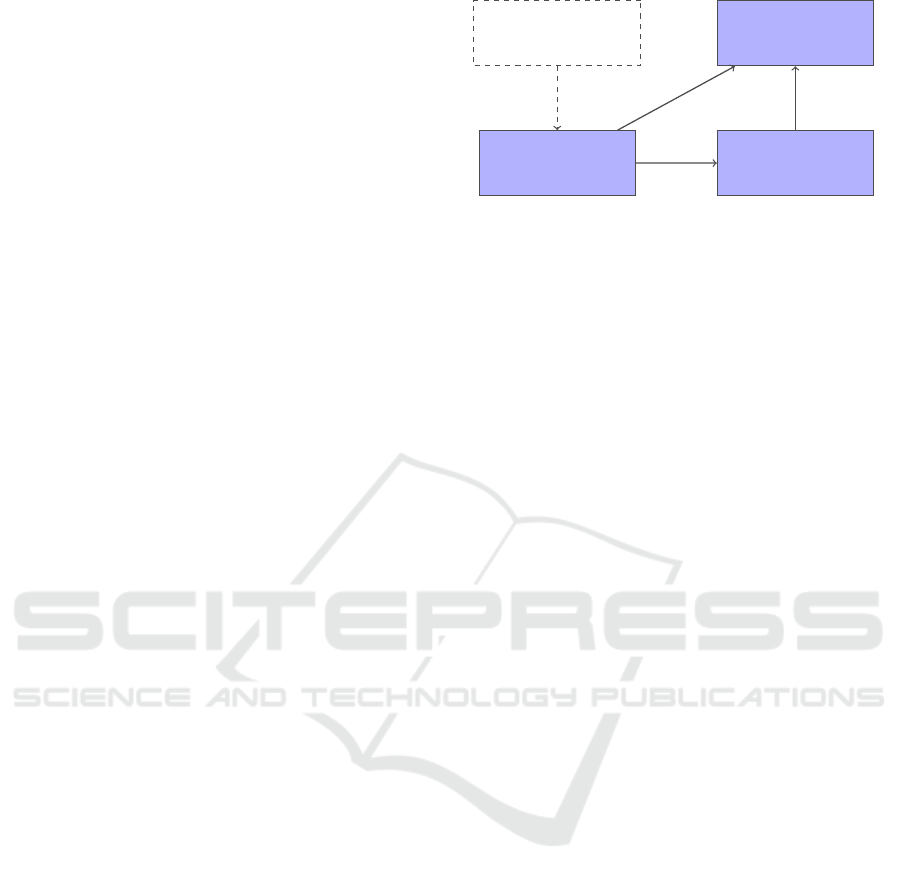
Figure 2: The workflow used to gradually introduce SBE.
Figure 2 illustrates this workflow, which currently
covers steps (1) and (2) of the approach, i.e., formal
modelling and design assistance.
Wafer flow is specified by ASML and VDL-ETG
in terms of UML activities, but in the absence of a
formal semantics of their execution. Therefore, as a
first step in setting up the workflow, we defined an
execution semantics for their activities. This execu-
tion semantics is different from existing semantics in
the literature, on two main aspects. Firstly, the ac-
tivities use specification concepts like action atomic-
ity and conditional waiting, which to the best of our
knowledge are not native in any existing off-the-shelf
execution semantics for activities; see Section 5 for a
more in-depth discussion. Secondly, these specifica-
tion concepts are needed to be able to connect to the
current ways of working. Section 4.1 formally defines
our execution semantics for UML activities.
These formalized activities enable integrating sup-
port for validation and verification into the workflow,
in the form of activity simulation and deadlock prop-
erty checking. This is done by leveraging existing
off-the-shelf tooling, particularly the Cameo Simula-
tion Toolkit (No Magic, nd) and ITS-tools (Thierry-
Mieg, 2015), by translating the formalized activities
to their input formalisms. Section 4.2 briefly explains
the translations, after which Section 4.3 discusses the
evaluation of the workflow with domain experts.
The next (work-in-progress) step, is to support au-
tomatic synthesis of UML activities. Support for ac-
tivity synthesis is not yet implemented in our work-
flow, since formalized models and design assistance
must be in place first. Nevertheless, we have shown
that activity synthesis is technically feasible; Sec-
tion 4.4 outlines the synthesis strategy. Integrating
this strategy into the workflow is thus future work.
4.1 Activities
Our workflow is built around formalized activities, for
which this section defines an execution semantics.
Activities are defined in the presence of state, for
example a set of variables and their current valuation.
MODELSWARD 2025 - 13th International Conference on Model-Based Software and Systems Engineering
162

We keep the notion of state more abstract for the pur-
pose of defining the semantics, and let State be the
set of all states. Users of this semantics could later
instantiate State as desired, e.g., as variable valuation
mappings. Let σ ∈ State be a typical state.
The main building blocks of activities are the ac-
tion nodes, which are nodes that carry out a cer-
tain action. An action α = (a, g,u) ∈ Action is a
triple consisting of an action label, a ∈ Label, a
guard, g ∈ Guard, and an effect, u ∈ Effect. Let
Action = Label × Guard × Effect be the universe set
of all actions, with Guard = State → B the set of
all guards, which are state predicates, and Effect =
State → 2
State
the set of all effects, which are state
transformers. The guard of any action must hold in
order for the action to be executed, and its effect de-
termines possible successor states after having per-
formed the action. For any action α = (a, g,u), let
guard(α) = g and effect(α) = u be projection func-
tions for obtaining the guard and effect of α, respec-
tively.
Activities A = (N,E) are defined as directed
graphs with N ⊆ Node a set of nodes and
E ⊆ N × Guard × N a set of guarded edges, with
Node = ID × Type. Activity nodes, n = (ℓ,t) ∈ Node,
consist of a node identifier ℓ used to give identity to
nodes (e.g., to allow activities to have multiple forks
and joins), and a node type t taken from the following
subset of standard UML activity node types:
Type ::= init | final | fork | join | decision | merge | act(α)
Action-typed nodes act(α) closely relate to
opaque actions in UML in the sense that their execu-
tion updates the current state according to α (possibly
non-deterministically so in case α’s effect has multi-
ple successor states to choose from). The other node
types are standard in UML. However, in UML, ac-
tivity nodes are typically subject to well-formedness
conditions in order for their execution to have mean-
ing. For example, initial nodes are not allowed to have
incoming edges. In contrast, our semantics does not
rely on any such well-formedness constraints.
We define a token-passing execution semantics for
activities. We thereby follow the style of (Daw and
Cleaveland, 2015), which divides Type into two be-
havioral categories: and-nodes requiring a token from
all incoming edges, such as fork and join; and or-
nodes requiring a token from a single incoming edge,
such as decision and merge. This classification allows
the execution semantics of activities to be defined in
terms of just two reduction rules: one for and-nodes
and one for or-nodes. To be able to define these two
reduction rules, we first define a notion of abstract ac-
tivities in which and and or are explicitly represented.
Then we define the two reduction rules in terms of
these abstract activities. Finally, we define the seman-
tics of activities as a translation to abstract activities.
Like (concrete) activities, abstract activities
A = (N ,E) are defined as directed graphs con-
sisting of (abstract) nodes N ⊆ AbstrNode and
guarded edges E ⊆ N × Guard × N . Abstract nodes
η ∈ AbstrNode with AbstrNode = ID × AbstrType, in
turn, are pairs consisting of a node identifier and an
abstract node type from AbstrType ::= and⟨α⟩ | or⟨α⟩
containing an action α and its execution strategy.
Later, when translating concrete activities to abstract
ones, we translate control-typed nodes like fork and
merge as special actions whose guards are always true
and whose effects do not change the state.
Let us introduce some convenient shorthand no-
tation. We define in(η) = {(η
s
,g,η
t
) ∈ E | η
t
= η}
to be the set of all incoming edges of η ∈ N in the
context of some abstract activity A = (N , E), and
in(η,σ) = {ε ∈ in(η)|guard(ε)(σ)} to be all incom-
ing edges of η whose guard holds with respect to state
σ ∈ State. Let out(η) and out(η, σ) be similarly de-
fined to instead capture the outgoing edges of η.
The two execution rules for abstract activities are
defined as a reduction relation between configura-
tions, in the sense that an execution step in an ab-
stract activity gets you from one configuration to an-
other configuration. A configuration c ∈ Config with
Config = 2
E
× State is defined to be a pair c = (Σ, σ)
with Σ ⊆ E a set of edges—the ones currently holding
a token—and σ a (current) state. Any edge ε is said to
be enabled in c if it has a token in c, i.e., if ε ∈ Σ. Note
that the edge guards do not influence whether an edge
is enabled or not. Instead, edge guards restrict when
an edge can receive a token (as opposed to whether
they can hold a token).
The execution semantics of abstract activities
A = (N ,E) is defined in terms of the single-step
labeled reduction relation
.
−→⊆ Config × N × Config.
Figure 3 shows the two reduction rules of
.
−→. The
AND rule defines the execution of nodes η of type
and⟨α⟩. It requires: (1) all incoming edges into η to
have a token; (2) none of the outgoing edges of η ex-
cept self-loops to have a token; (3) the guard of α to
hold with respect to the current state σ; (4) a succes-
sor state σ
′
to be available from α’s effect; and (5) the
guards of all outgoing edges to hold with respect to
σ
′
. If these requirements are all met, AND removes all
tokens from in(η) and puts tokens on out(η), making
(Σ \ in(η)) ∪ out(η) the new arrangement of tokens.
The OR rule defines the execution of nodes η of
type or⟨α⟩. It requires: (1) the existence of an incom-
ing edge ε of η that is enabled; (2) the existence of
an outgoing edge ε
′
of η that is not enabled unless it
Towards Synthesis-Based Engineering for Cyber-Physical Production Systems
163

AND
η = (ℓ, and⟨α⟩)
in(η) ⊆ Σ (out(η) \in(η))∩ Σ =
/
0 guard(α)(σ) σ
′
∈ effect(α)(σ) out(η) = out(η, σ
′
)
(Σ,σ)
η
−→ ((Σ \ in(η)) ∪ out(η), σ
′
)
OR
η = (ℓ, or⟨α⟩) ε ∈ in(η) ∩ Σ ε
′
∈ out(η,σ
′
)\(Σ\{ε}) guard(α)(σ) σ
′
∈ effect(α)(σ)
(Σ,σ)
η
−→ ((Σ \ {ε}) ∪ {ε
′
},σ
′
)
Figure 3: The execution semantics of abstract activities, where c
η
−→ c
′
is shorthand notation for (c,η, c
′
) ∈
.
−→.
[[(ℓ, init)]]
n
= (ℓ,or⟨(init,λσ.true, λσ.σ)⟩)
[[(ℓ, final)]]
n
= (ℓ,or⟨(final,λσ.true, λσ.σ)⟩)
[[(ℓ, fork)]]
n
= (ℓ,and⟨(fork, λσ.true, λσ.σ)⟩)
[[(ℓ, join)]]
n
= (ℓ,and⟨(join,λσ.true, λσ.σ)⟩)
[[(ℓ, decision)]]
n
= (ℓ,or⟨(decision,λσ.true, λσ.σ)⟩)
[[(ℓ, merge)]]
n
= (ℓ,or⟨(merge,λσ.true, λσ.σ)⟩)
[[(ℓ, act(α))]]
n
= (ℓ,and⟨α⟩)
Figure 4: The translation from concrete activity nodes to
abstract activity nodes.
equals ε, and whose guard holds with respect to σ
′
;
(3) the guard of α to hold with respect to the current
state σ; and (4) a successor state σ
′
to be available
from α’s effect. The OR rule allows multiple input
edges to be enabled, but only one of them will par-
ticipate per application of the OR rule. Similarly, if
multiple outgoing edges could potentially participate,
one of them actually participates. If these require-
ments are met, OR removes the token from ε and puts
it on ε
′
, making (Σ \ {ε}) ∪ {ε
′
} the new arrangement
of tokens.
This reduction relation
.
−→ defines an atomic ex-
ecution semantics in the sense that actions are exe-
cuted atomically: in a single execution step, the action
guard is evaluated and a successor state is determined
from the action effect.
The last step is defining the semantics of con-
crete activities, which we do by translating them
to abstract activities to allow AND and OR to give
meaning to concrete node types. The translation
of activity nodes is defined as a translation function
[[ · ]]
n
: Node → AbstrNode, under the assumption that
the set Label of action labels is chosen in such a way
to contain ‘reserved labels’ for all control node types,
i.e., all node types except act. Figure 4 shows the def-
inition of [[ · ]]
n
. In this definition, λσ.true is the con-
stant guard that is always true, and λσ.σ the identity
effect that leaves any state unchanged. Fork and join
nodes are both translated to and-type nodes, allowing
fork nodes to produce multiple tokens in order to ini-
tiate concurrency, and join nodes to consume multiple
tokens in order to behave like a barrier. Action nodes
act are also translated to abstract and nodes, since this
is consistent with fUML semantics, which describes
action nodes to behave like an “implicit fork” (Object
Management Group, 2021). All other node types are
translated to or-type nodes as their execution produces
and consumes tokens on single edges.
The translation of edges is straightforward, since
it simply amounts to translating the source and tar-
get node of the edge using [[ · ]]
n
. The translation of
edges is defined as a function [[ · ]]
e
: Node × Guard ×
Node → AbstrNode × Guard × AbstrNode such that
[[(n, g, n
′
)]]
e
= ([[n]]
n
,g,[[n
′
]]
n
).
Let the translation of any (concrete) activ-
ity A = (N, E) be defined as [[A]] = ({[[n]]
n
|n ∈
N},{[[e]]
e
|e ∈ E}). Then the semantics of A is de-
fined to be the semantics of [[A]].
This finishes the definition of the execution se-
mantics of activities, except for the starting points for
their execution. The starting point of executing con-
crete activities are their init nodes. Since initial nodes
are translated to or-type nodes, the execution of an ac-
tivity is started along exactly one outgoing edge of a
(single) init node. In case an activity has multiple ini-
tial nodes, and/or in case there are initial nodes with
multiple outgoing edges, the activity has multiple po-
tential initial configurations. Given any (concrete) ac-
tivity A = (N,E), the configuration ({ε}, σ
I
) ∈ Config
is defined to be an initial configuration of A for any
choice of initial state σ
I
∈ State, if there exists an ini-
tial node (ℓ, init) ∈ N such that ε ∈ out([[(ℓ, init)]]
n
,σ
I
).
That is, any outgoing edge of any initial node can
form an initial configuration together with some ini-
tial state σ
I
, given that this edge is allowed by its
guard to receive a token in the initial state σ
I
.
Finally, with respect to compositionality, activities
are being used in a hierarchical manner: activities can
call other activities by means of call actions. That
is, concrete activities come with an additional type
Type ::= · ·· | call(ı) and are executed in a context of
a number of activities A
0
,. . . , A
n
, where ı ∈ {0, ..., n}
is a reference to one of those activities. We disallow
(in)direct recursion, so that hierarchy is maintained.
MODELSWARD 2025 - 13th International Conference on Model-Based Software and Systems Engineering
164

By doing so, such extended activities can be flattened
into single activities without any call actions, by in-
lining any activity being called, thereby replacing the
call action. Therefore, the semantics of these extended
activities is defined to be the semantics of the flattened
single activity.
4.2 Workflow
This activity formalism constitutes the basis of the
workflow since its execution semantics enables sup-
port for design assistance and synthesis. Design as-
sistance is provided by leveraging existing tooling for
simulation and deadlock property checking, by trans-
lating activities to their input formalisms.
For (formal) modeling UML Designer (Obeo, nd)
is used, which is a graphical tool for construct-
ing UML diagrams, including activities. The work-
flow thereby uses UML activities, but annotated with
data properties (constituting state), and (action/edge)
guards and effects that are expressed (for now) in
the CIF language (van Beek et al., 2014). We then
consider these activities under the execution seman-
tics defined earlier. The use of an existing UML tool
makes formalizing activities accessible.
For simulation the Cameo Simulation Toolkit (No
Magic, nd) is used, which provides extensive sim-
ulation support for activities under the semantics of
fUML. Although fUML handles action execution dif-
ferently than the execution semantics as defined in
Section 4.1 (which is further detailed in Section 5),
our execution semantics can be encoded in terms of
fUML constructs, e.g., by using different UML con-
cepts like events and signals to encode the notion of
action atomicity. Therefore, for simulation we have
devised an automated UML-to-fUML transformation
that translates action guards/effects, and their atomic
execution semantics, into fUML specifications that
can be simulated using the Cameo Simulation Toolkit.
For verification the model checker ITS-
tools (Thierry-Mieg, 2015) is used, which supports
checking reachability, LTL, and CTL properties, us-
ing a symbolic back-end. The use of symbolic model
checking techniques helps to analyze industry-scale
specifications. The input formalism of ITS-tools
is a compositional model called ITS (Instantiable
Transition Systems) (Thierry-Mieg et al., 2009)
expressed in a DSL called GAL—the Guarded
Action Language. ITS and GAL are well-suited
for translating activities to, since they come with a
Petri net style concurrent semantics that lies close to
our execution semantics. We have implemented an
proof-of-principle automated UML-to-GAL transfor-
mation for activities, to enable verification. Deadlock
properties for activities are then expressed as CTL
properties that are roughly of the form: ‘it globally
holds that, unless there are no more products/wafers
to process, there must always exist an activity node
that can be executed’. Any violation of this property
leads to a counterexample, i.e., a trace from an initial
configuration to a configuration where no further
progress is possible, which may then be simulated.
4.3 Evaluation
We have empirically evaluated our first workflow with
architects and engineers from ASML and VDL-ETG
by means of two validation phases. In the first phase
we investigated whether the workflow can add value
to the wafer handler development process by finding
potential problems early. In the second phase we in-
vestigated whether formal modeling and design assis-
tance would suit the current way of working.
For the first validation phase, we formalized a par-
ticularly complex part of the wafer handler specifi-
cation that comprises over 90 activities in total, to
be able to simulate and verify it, thereby following
the proposed workflow. As a result, we automati-
cally found multiple potential deadlock situations re-
sulting from subtle interleavings of concurrently exe-
cuting activities, that we could present to the domain
experts—the architects and engineers. Such deadlock
situations are difficult to find without design assis-
tance due to the high complexity. The domain experts
indicated that, although we might miss some contex-
tual restrictions due to having formalized only part of
the overall specification, some of the found situations
might be actual deadlock behaviors, though possibly
non-production mode ones. They recognize the value
of design-time validation and verification, and later
synthesis for automatically computing solutions for
such situations, and expressed interest in exploring
the integration of these techniques into their current
way of working.
Therefore, for the second validation phase, we for-
malized another part of the specification in a session
together with domain experts, aimed to get feedback
on the workflow and identify follow-up steps towards
its adoption. The outcome was positive: the domain
experts indicated to be willing to put effort in for-
malizing their specifications, but that first some fur-
ther engineering is needed to make the workflow suf-
ficiently user friendly, e.g., by adding type checking
support of guard expressions, and convenient UI sup-
port for specifying guards and effects. We are cur-
rently working on further maturing the workflow ac-
cording to this feedback.
Towards Synthesis-Based Engineering for Cyber-Physical Production Systems
165

4.4 Activity Synthesis
The next step after formalizing the activities and pro-
viding design assistance, is providing support for syn-
thesis. Although our workflow currently does not sup-
port activity synthesis, we have preliminary results
showing that such synthesis is technically feasible,
and can be automated (Laar, 2023).
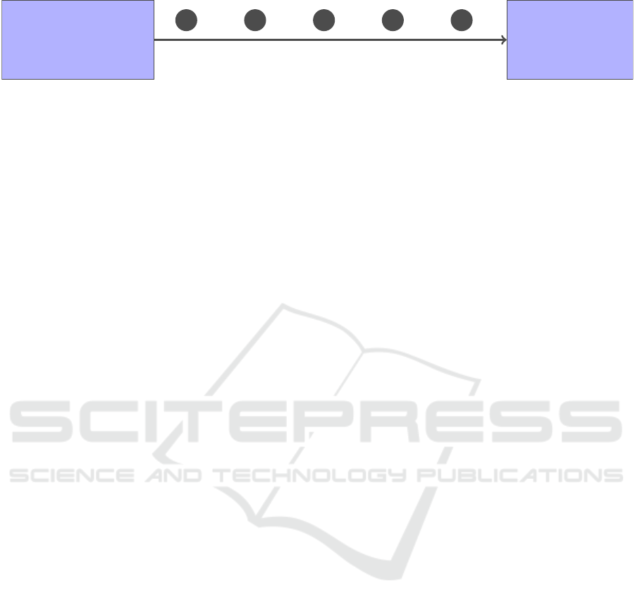
Figure 5 shows the strategy for automatically syn-
thesizing UML activities, as was used in our feasi-
bility study. Firstly, a supervisory controller is syn-
thesized from a specification of plants, requirements,
and pre- and postconditions for the to-be-synthesized
activity. Secondly, the state space of all safe behavior
as allowed by the synthesized supervisor is generated.
Thirdly, a minimal Petri net is synthesized from this
safe state space using the theory of regions (Badouel
and Darondeau, 1998). Minimality of these Petri nets
means that concurrent interleavings (diamond shapes)
in state spaces are reduced to fork-join patterns where
possible. Finally, the Petri net is translated to a UML
activity.
For demonstrating feasibility, we resynthesized
part of the wafer handler control specifications us-
ing this strategy. The synthesis specification was ex-
pressed in CIF for the purpose of showing feasibility,
and the controller synthesis is performed with Eclipse
ESCET™ (Fokkink et al., 2023a)
4
. Moreover, we
used Petrify (Cortadella et al., 1997) for synthesiz-
ing a minimal Petri Net. Overall, the main technical
challenge of synthesizing activities is synthesizing the
guards of edges out of decision nodes, since existing
techniques for Petri net synthesis do not handle data.
5 RELATED WORK
Numerous individual case studies of formal methods
being applied in industry have been reported (Bicar-
regui et al., 2009), e.g., by academic communities like
iFM
5
and FMICS
6
. Moreover, various conceptual so-
lutions, guidelines and experiences are reported on
integrating formal methods into industrial practice in
a broad sense (Nyberg et al., 2018; Huisman et al.,
2022; Gleirscher et al., 2023). However, to the best of
our knowledge, a structured approach for integrating
4
See https://eclipse.dev/escet (Accessed 2024-12-18).
‘Eclipse’, ‘Eclipse ESCET’ and ‘ESCET’ are trademarks
of Eclipse Foundation, Inc.
5
Integrated Formal Methods; http://www.
ifmconference.org (Accessed 2024-12-18).
6
The ERCIM Working Group on Formal Methods for
Industrial Critical Systems; https://fmics.inria.fr (Accessed
2024-12-18).
SBE into industrial practices has not been proposed
earlier.
General recommendations for industrial integra-
tion of formal methods are given in (Huisman et al.,
2022), which are in line with our approach and work-
flow, e.g., investigating existing practices and tool-
ing, keeping end-users in mind, and gradually inte-
grating formal methods by starting lightweight. Ex-
periences on gradually introducing ASD
7
—a formal
approach for modeling, checking of standard prop-
erties and code generation—into an industrial work-
flow at Philips Healthcare are reported in (Osaiweran
et al., 2013) and shown to lead to a reduced defect
rate. In (Nyberg et al., 2018), enablers and obsta-
cles are discussed for introducing formal verification
at Scania. One highlighted obstacle is that formally
modelling code implementations for automated anal-
ysis, e.g., deductive verification or model checking,
is challenging. Our strategy is to apply formal meth-
ods at design time while staying close to current prac-
tices. Integrating formal methods by strongly con-
necting to current practices is also a key principle as
proposed in a recent manifesto on applicable formal
methods (Gleirscher et al., 2023).
With respect to existing semantics for activities;
the current standard semantics for (a subset of) UML
activities is Foundational UML (fUML). However,
fUML’s execution semantics is not formally defined
but rather given the form of pseudo-Java (Laurent
et al., 2014), making it difficult to use for verifica-
tion and synthesis. As a consequence, various alter-
native semantics have been proposed, like (Laurent
et al., 2014; Abdelhalim et al., 2010; Lima et al.,
2013) which define the semantics in terms of math-
ematical languages like CSP or relational calculi, or
do not handle action guards and effects.
Moreover, fUML’s execution semantics does not
natively handle action atomicity nor conditional wait-
ing (i.e. handling of edge guards), which are concepts
needed not only to properly connect to current ways
of working, but also to ease integration with verifi-
cation and synthesis tooling. In fUML there is no
native concept of waiting for an action/edge guard
to become true before execution should resume. In-
stead, if no immediate progress can be made (e.g.,
none of the outgoing edges of a decision node can
currently be taken) then activity execution will di-
rectly terminate. Likewise, for concurrently-enabled
actions, fUML does not guarantee that they execute
atomically, only that they are executed after forking
and before joining. Nevertheless, action atomicity
and conditional waiting can be encoded by means of
7
Analytical Software Design; https://www.verum.com/
asd (Accessed 2024-12-18).
MODELSWARD 2025 - 13th International Conference on Model-Based Software and Systems Engineering
166
Formal synthesis
specifications
(Plants and requirements)
Formal control
specifications
(UML activities)
1 2 3 4 5
Automatic synthesis
Transform
to state
machines
Synthesize
supervisory
controller
Compute
state space
of all safe
behavior
Synthesize
minimal
Petri net
Translate
to activity
Figure 5: The high-level strategy for synthesizing UML activities.
native fUML constructs, e.g., by using UML events
and signals to implement a global locking mechanism
to achieve atomicity. We perform such encodings in
our UML-to-fUML translation for simulation. Fur-
thermore, atomic actions with guards and effects can
straightforwardly be translated to formalisms for ver-
ification and synthesis in a consistent manner, e.g.,
to transition guards/bodies in case of GAL, and edge
guards/updates in case of CIF.
Our semantics of activities closely corresponds to
(colored) Petri Nets, since UML 2.x uses a Petri Net
based model (Daw and Cleaveland, 2015). The ex-
ecution of and-nodes corresponds to transition firing
in Petri Nets. The execution of or-nodes is slightly
different since it only distributes a single token.
Other notable related formalisms are BPMN (Di-
jkman et al., 2008), used to model business processes,
and SysML v2, for which an execution semantics for
activities is not defined (Jansen et al., 2022).
6 CONCLUSION
This article presents a three-step approach to intro-
duce SBE in industrial settings. Since SBE is differ-
ent from traditional engineering approaches, it should
be integrated gradually to help in its acceptance.
Moreover, every (next) migration step should add (ad-
ditional) value to the development process, e.g., by in-
creasingly automating control design. We took initial
steps towards such integration, by instantiating our
approach in a research case together with ASML and
VDL-ETG in the form of a formal modeling work-
flow supported by automated design assistance. The
specification formalism used in the workflow is based
on UML activities, for which this article contributes a
formal execution semantics, which is otherwise miss-
ing. We evaluated this workflow with domain experts,
who considered the workflow conceptually valuable,
and, when made sufficiently user-friendly, would like
to use it to formalize their specifications and thereby
enable design assistance and eventually synthesis.
As future work, we are developing the automated
activity synthesis strategy as sketched in Section 4.4.
This enables step three in our approach: automati-
cally synthesizing wafer control specifications based
on formal requirements that are specified by engineers
and architects themselves. Moreover, we will further
integrate and evaluate steps one and two of our ap-
proach at ASML and VDL-ETG—formal modelling
of UML activities and their design assistance.
ACKNOWLEDGEMENTS
The authors thank ASML and VDL-ETG for the col-
laboration on this project, and especially Abdullah
Alabsawi (VDL-ETG), Falco Creemers (VDL-ETG),
Jip Reinders (VDL-ETG), Joost van Leeuwen (VDL-
ETG), Prabhat Kumar Sharma (VDL-ETG), Rainer
Wolf (ASML), and Saurab Rajkarnikar (VDL-ETG)
for their help and efforts in validating the workflow.
This research is partly carried out at part of the
Poka Yoke program under the responsibility of TNO-
ESI in cooperation with ASML and VDL-ETG. Poka
Yoke is funded by Holland High Tech — TKI HSTM
via the PPP Innovation Scheme (PPP-I) for public-
private partnerships.
REFERENCES
Abdelhalim, I., Sharp, J., Schneider, S., and Treharne, H.
(2010). Formal Verification of Tokeneer Behaviours
Modelled in fUML Using CSP. In Dong, J. and Zhu,
H., editors, ICFEM, pages 371–387. Springer Berlin
Heidelberg.
Badouel, E. and Darondeau, P. (1998). Theory of regions,
pages 529–586. Springer Berlin Heidelberg.
Baeten, J., Mortel-Fronczak, J. v. d., and Rooda, J.
(2016). Integration of Supervisory Control Synthesis
in Model-Based Systems Engineering, pages 39–58.
Springer International Publishing.
Bicarregui, J., Fitzgerald, J., Larsen, P., and Woodcock, J.
(2009). Industrial Practice in Formal Methods: A Re-
view. In Cavalcanti, A. and Dams, D., editors, FM,
pages 810–813. Springer Berlin Heidelberg.
Cortadella, J., Kishinevsky, M., Kondratyev, A., Lavagno,
L., and Yakovlev, A. (1997). Petrify: a tool for ma-
nipulating concurrent specifications and synthesis of
Towards Synthesis-Based Engineering for Cyber-Physical Production Systems
167

asynchronous controllers. EICE Transactions on In-
formation and Systems, E80-D(3):315–325.
Daw, Z. and Cleaveland, R. (2015). Comparing model
checkers for timed UML activity diagrams. Science
of Computer Programming, 111:277–299.
Dijkman, R., Dumas, M., and Ouyang, C. (2008). Se-
mantics and analysis of business process models
in BPMN. Information and Software Technology,
50(12):1281–1294.
Fokkink, W., Goorden, M., Hendriks, D., Beek, D. v.,
Hofkamp, A., Reijnen, F., Etman, L., Moormann,
L., Mortel-Fronczak, J. v. d., Reniers, M., Rooda, J.,
Sanden, B. v. d., Schiffelers, R., Thuijsman, S., Ver-
bakel, J., and Vogel, J. (2023a). Eclipse ESCET™:
The Eclipse Supervisory Control Engineering Toolkit.
In Sankaranarayanan, S. and Sharygina, N., editors,
TACAS, pages 44–52. Springer Nature Switzerland.
Fokkink, W., Goorden, M., Hendriks, D., Mortel-Fronczak,
J. v. d., Oortwijn, W., and Rooda, J. (2023b).
Synthesis-Based Engineering of Supervisory Con-
trollers. Mikroniek, 6:22–26.
Fokkink, W., Goorden, M., Mortel-Fronczak, J. v. d., Rei-
jnen, F., and Rooda, J. (2022). Supervisor Synthesis:
Bridging Theory and Practice. Computer, 55(10):48–
54.
Gleirscher, M., Pol, J. v. d., and Woodcock, J. (2023). A
manifesto for applicable formal methods. Software
and Systems Modeling, 22:1737–1749.
Hegge, J., Hendriks, D., Laar, P. v. d., Sanden, B.
v. d., Oortwijn, W., and Yang, N. (2023). State-
of-the-art study on formalisms and methods to
specify and analyze flows in logistic processes.
TNO Report 2023-R12176, https://repository.tno.nl/
SingleDoc?docId=57891 (Accessed 2024-12-18).
Huisman, M., Gurov, D., and Malkis, A. (2022). Formal
Methods: From Academia to Industrial Practice. A
Travel Guide.
Jansen, N., Pfeiffe, J., Rumpe, B., Schmalzing, D., and
Wortmann, A. (2022). The Language of SysML v2
under the Magnifying Glass. The Journal of Object
Technology, 21.
Laar, P. v. d. (2023). Synthesis-Based Engineer-
ing of Activity Diagrams. Presentation at
the 2nd Eclipse ESCET community meeting.
https://gitlab.eclipse.org/eclipse/escet/escet/uploads/
44f7235a5f3a4304bbe78355c718d5d9/3 - Eclipse
ESCET community meeting 2 - Synthesis-Based
Engineering of activity diagrams.pdf (Accessed
2024-12-18).
Laurent, Y., Bendraou, R., Baarir, S., and Gervais, M.
(2014). Formalization of fUML: An Application to
Process Verification. In Jarke et al., M., editor, CAiSE,
pages 347–363. Springer International Publishing.
Lima, L., Didier, A., and Corn
´
elio, M. (2013). A Formal
Semantics for SysML Activity Diagrams. In Iyoda,
J. and Moura, L. d., editors, SBMF, pages 179–194.
Springer Berlin Heidelberg.
Linden, F. v. d., Schmid, K., and Rommes, E. (2007). Soft-
ware Product Lines in Action: The Best Industrial
Practice in Product Line Engineering. Springer Sci-
ence & Business Media.
No Magic (n.d.). Cameo Simulation Toolkit.
https://www.3ds.com/products/catia/no-magic/
cameo-simulation-toolkit (Accessed 2024-12-18).
Nyberg, M., Gurov, D., Lidstr
¨
om, C., Rasmusson, A., and
Westman, J. (2018). Formal Verification in Automo-
tive Industry: Enablers and Obstacles. In Margaria,
T. and Steffen, B., editors, ISoLA, pages 139–158.
Springer International Publishing.
Obeo (n.d.). UML Designer. https://www.umldesigner.org
(Accessed 2024-12-18).
Object Management Group (2021). Semantics of a
Foundational Subset for Executable UML Models
(fUML), v1.5. https://www.omg.org/spec/FUML/1.5
(Accessed 2024-12-18).
Osaiweran, A., Schuts, M., Hooman, J., and Wesselius, J.
(2013). Incorporating formal techniques into indus-
trial practice: an experience report. In FESCA, pages
49–63.
Ramadge, P. and Wonham, W. (1987). Supervisory Control
of a Class of Discrete Event Processes. SIAM Journal
on Control and Optimization, 25(1):206–230.
Reijnen, F. (2020). Putting supervisor synthesis to work:
controller software generation for infrastructural sys-
tems. PhD thesis.
Reijnen, F., Erens, T., Mortel-Fronczak, J. v. d., and Rooda,
J. (2022). Supervisory controller synthesis and imple-
mentation for safety PLCs. Discrete Event Dynamic
Systems, 32:115–141.
Sanden, B. v. d., Reniers, M., Geilen, M., Basten, T., Ja-
cobs, J., Voeten, J., and Schiffelers, R. (2015). Mod-
ular model-based supervisory controller design for
wafer logistics in lithography machines. In MODELS,
pages 416–425.
Sheridan, T. and Johannsen, G. (1976). Monitoring Behav-
ior and Supervisory Control. Springer New York.
Thierry-Mieg, Y. (2015). Symbolic Model-Checking Us-
ing ITS-Tools. In Baier, C. and Tinelli, C., editors,
TACAS, pages 231–237. Springer Berlin Heidelberg.
Thierry-Mieg, Y., Poitrenaud, D., Hamez, A., and Kordon,
F. (2009). Hierarchical Set Decision Diagrams and
Regular Models. In Kowalewski, S. and Philippou,
A., editors, TACAS, pages 1–15. Springer Berlin Hei-
delberg.
van Beek, D., Fokkink, W., Hendriks, D., Hofkamp, A.,
Markovski, J., Mortel-Fronczak, J. v. d., and Reniers,
M. (2014). CIF 3: Model-Based Engineering of Su-
pervisory Controllers. In
´
Abrah
´
am, E. and Havelund,
K., editors, TACAS, pages 575–580. Springer Berlin
Heidelberg.
Wonham, W., Cai, K., and Rudie, K. (2018). Supervisory
control of discrete-event systems: A brief history. An-
nual Reviews in Control, 45:250–256.
MODELSWARD 2025 - 13th International Conference on Model-Based Software and Systems Engineering
168
