
An Easy-to-Use System for Tracking Robotic Platforms Using
Time-of-Flight Sensors in Lab Environments
Andr
´
e Kirsch and Jan Rexilius
Bielefeld University of Applied Sciences and Arts, 32427 Minden, Germany
Keywords:
Tracking, Robot, Drone, MAV, External, Time-of-Flight, LiDAR.
Abstract:
The acquisition of accurate tracking data is a common problem in scientific research. When developing new
algorithms and AI networks for the localization and navigation of mobile robots and MAVs, they need to be
evaluated against true observations. Off-the-shelf systems for capturing ground truth data often come at a high
cost, since they typically include multiple expensive sensors and require a special setup. We see the need
for a simpler solution and propose an easy-to-use system for small scale tracking data acquisition in research
environments using a single or multiple sensors with possibly already available hardware. The system is able
to track mobile robots moving on the ground, as well as MAVs that are flying through the room. Our solution
works with point clouds and allows the use of Time-of-Flight based sensors like LiDAR. The results show that
the accuracy of our system is sufficient to use as ground truth data with a low-centimeter mean error.
1 INTRODUCTION
Ground truth data is an important requirement to cor-
rectly assess the accuracy of navigation and local-
ization algorithms and is also used for training rein-
forcement learning networks for mobile robots and
micro aerial vehicles (MAVs), hereafter summarized
as robotic platforms. The data contains positional
information and sometimes also information about
the orientation of the robotic platform. But captur-
ing valid tracking data typically requires some sort
of motion capturing system like OptiTrack
1
, which
come at a high cost. There are other cheaper alter-
natives available, each having different advantages
and disadvantages, like the Lighthouse positioning
system (Taffanel et al., 2021) and Ultra-Wideband
(UWB) (Shule et al., 2020), which require hardware
mounted on the tracked object.
We focus on Time-of-Flight (ToF) based technolo-
gies like LiDAR, as they do not require any lighting in
the environment and can track unknown objects that
have no tags or special hardware attached to them.
Time-of-Flight is a technology that computes distance
based on how much time light or sound needs to travel
until it hits something and bounces back. For light, a
typical wavelength is infrared. It is often either emit-
ted using LEDs for low-range ToF devices or using
a laser in case of LiDAR. Sending out light waves as
1
https://optitrack.com/
a laser has the advantage of the light reaching farther
distances and therefore covering a larger area.
In this paper, we present a system for tracking
robotic platforms using Time-of-Flight for tracking
data acquisition, as shown in figure 1. The system
focuses on lab environments and can be used with
different types of Time-of-Flight-based sensors that
capture point clouds. Its main goal is to make cap-
turing position data more accessible since it does not
rely on a specific sensor. This enables the use of sen-
sors already available to a researcher, which might
have become unused after finishing an earlier research
project. This omits the need to invest into a costly mo-
tion capturing system. The proposed system should
be easy to install and already be useable with a single
sensor, while being scalable to multi sensor setups.
Multi sensor setups can increase the recording area
or capture the scene from a different angle. Please
note, that the tracking accuracy, frequency, and range
highly depend on the selected sensor. Furthermore,
there is no need to install additional hardware on the
robotic platform when using our system.
2 RELATED WORK
Camera-based motion capturing systems are the gold
standard for tracking objects in a confined space and
are often used to record ground truth data due to their
Kirsch, A. and Rexilius, J.
An Easy-to-Use System for Tracking Robotic Platforms Using Time-of-Flight Sensors in Lab Environments.
DOI: 10.5220/0013110500003905
In Proceedings of the 14th International Conference on Pattern Recognition Applications and Methods (ICPRAM 2025), pages 571-578
ISBN: 978-989-758-730-6; ISSN: 2184-4313
Copyright © 2025 by Paper published under CC license (CC BY-NC-ND 4.0)
571
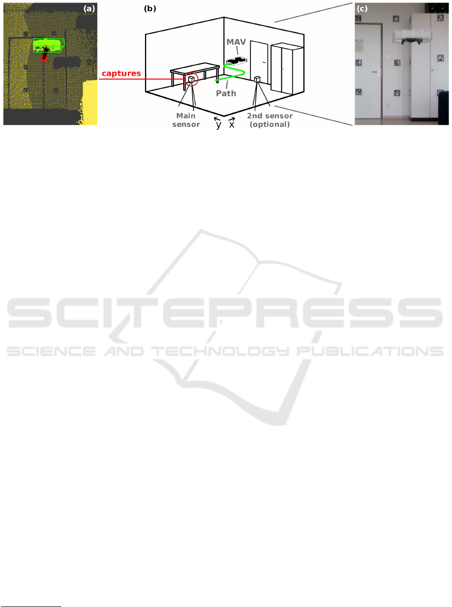
Figure 1: Visualization of the setup of the proposed system. Subfigure (b) shows the recording area with two installed sensors.
At least one sensor is required. Additional sensors can be used to either increase the size of the recording area or to capture
the recording area from a different angle, as shown in the image. The captured data is visualized in subfigure (a), where our
system is tracking the detected MAV. Subfigure (c) shows a real-life view of a part of the recording area captured from the
view of the main sensor.
millimeter-level accuracy, as shown in (Furtado et al.,
2019). Popular systems include OptiTrack, Vicon
2
and Qualysis
3
, which come at a high cost and re-
quire a complex setup of multiple sensors in a des-
ignated area. They either use active or passive mark-
ers attached to the tracked object that emit or reflect
infrared (IR) light, respectively. This light is cap-
tured by multiple special cameras. Through triangu-
lation of the captured data, it is possible to calculate
the position of the markers in 3D space. A cheaper
open-source alternative that uses markers is Easy Ro-
Cap (Wang et al., 2024), which is specifically de-
signed for tracking mobile robots and MAVs. It uses
infrared sensors from multiple Intel RealSense depth
cameras. There are also commercial markerless mo-
tion capturing systems but these mainly focus on the
tracking of humans.
Another IR-based system for tracking MAVs is the
Lighthouse Positioning system (Taffanel et al., 2021).
Multiple base stations emit IR light through moving
sweep planes. This light is captured by multiple IR
receivers mounted on the tracked MAV. The position
is calculated on-board the MAV. With lower velocity
and in a confined space, this method can reach accura-
cies of less than a centimeter. Ultra-Wideband is an-
other alternative, requiring active components on the
tracked hardware. As the name suggests, it utilizes
radio technology to determine the location of tracked
objects. An outline of this technology is given by
(Shule et al., 2020). As we want the location esti-
mation to be computed independently of the tracked
object, we focus on a different method. We use ToF
sensors that are part of the environment and capture
data without communication with the tracked object
required.
2
https://www.vicon.com/
3
https://www.qualisys.com/
2.1 Time-of-Flight-Based Methods
Compared to the aforementioned methods, Time-of-
Flight and especially LiDAR are used in a variety
of use cases. Its advantage over other approaches is
that it does not require any active or passive hard-
ware mounted on the tracked object. Therefore, it
is a preferred technology for tracking unknown ob-
jects and has formed the research area of 3D single
object tracking (3DSOC), including the pioneering
works of SC3D (Giancola et al., 2019) and P2B (Qi
et al., 2020). SC3D uses a Siamese tracker, while
P2B leverages PointNet++ (Qi et al., 2017). More
recent solutions to the problem include PTTR and
PTTR++ (Zhou et al., 2022), as well as P2P (Nie
et al., 2024), which also use some sort of AI network.
The networks are commonly evaluated and compared
using outdoor LiDAR sequences of a driving car, as in
the KITTI dataset (Geiger et al., 2013). Object classes
therefore include different types of cars, pedestrians,
and cyclists. None of the mentioned AI-based re-
search has been designed and tested with robotic plat-
forms in mind, which in our case are typically smaller
compared to their evaluated object classes.
The research on tracking mobile robots is much
more sparse. This might be due to the large variety
in forms and sizes, but also because swarms of mo-
bile robots are typically connected through a network
and can exchange their position information. (Yilmaz
and Bayindir, 2022) and (Was¸ik et al., 2015) use a
2D LiDAR sensor to find mobile robots of the same
type as the carrier of the sensor in the environment,
also known as kin detection. (Pleterski et al., 2023)
do kin detection for miniature mobile robots using
an ultralow-resolution ToF sensor. They train a CNN
on the depth images to determine if a mobile robot is
present in the image.
With the recent publications of the LiDAR-based
ICPRAM 2025 - 14th International Conference on Pattern Recognition Applications and Methods
572
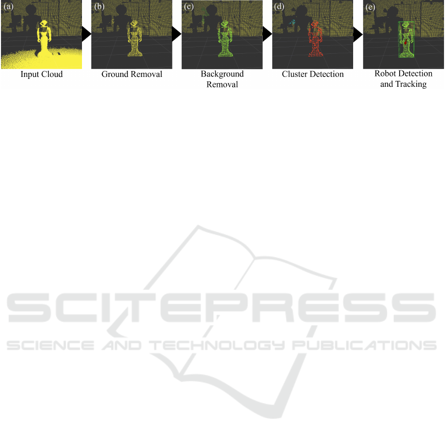
Figure 2: Overview of the proposed pipeline using the Pepper mobile robot as an example. An input cloud is shown in (a).
The other subfigures (b)-(e) show the different stages of the pipeline as described in the sections 3.2-3.5. For visualization
reasons, the background is shown in all images in yellow. Note that we downsampled the point cloud for performance reasons.
MAV datasets by (Catalano et al., 2023b) for gen-
eral MAV detection and tracking, and by (Yuan et al.,
2024) for drone threat detection, there is a stronger
focus on detection and tracking of drones in point
clouds compared to mobile robots. Compared to
3DSOC, both AI-based and traditional methods are
researched to solve this problem. Initial groundwork
has been done by (Dogru and Marques, 2022) and
(Wang et al., 2021). Other traditional methods include
works done by (Qingqing et al., 2021) and (Cata-
lano et al., 2023a), who integrate multiple scans us-
ing different frequencies to improve accuracy, as well
as (Gazdag et al., 2024), who use a particle filter for
tracking and utilize the scanning pattern of the LiDAR
sensor. For AI-based methods, (Sier et al., 2023) fuse
2D signal image provided by the sensor and point
clouds to detect MAVs. Point clouds are used in a
consecutive step to extract the MAV pose. (Chen
et al., 2024) detect MAVs in RGB image data and
again use point clouds for position estimation. The
tracking of MAVs by (Deng et al., 2024) is primar-
ily based on LiDAR captures and incorporates Radar
data. MAVs are detected through a combination of
an attention-based LSTM, a PointNet-based module,
and an MLP. Since detection and tracking of robotic
platforms using AI-based methods is still in its early
stages and often merges different sensor types, we fo-
cus on traditional approaches in our implementation.
3 CONCEPT
This paper proposes a system for tracking and de-
tecting mobile robots and MAVs in lab environments.
The main use case of the system is to capture position
data of a specified robotic platform. The user pro-
vides a captured or a live stream of point clouds to
the system. Since the system is implemented using
the Robot Operating System (ROS), different sensors
can be used directly. Compared to other solutions, our
system does not rely on specific hardware and can use
any type of Time-of-Flight based sensor available to
the user. Please note that the accuracy and frequency
heavily depend on the selected sensor. It is also possi-
ble to combine the recordings of multiple sensors and
feed the result into the system. Furthermore, the user
only needs to specify the dimensions of robotic plat-
forms to track. The system does not require any other
knowledge and does not make any additional assump-
tions about the platform to avoid falsifying the input
data. Figure 2 shows an overview of our approach.
The following subsections explain each part in more
detail.
3.1 Input Data
The input is a point cloud representing the tracking
area. For a single sensor, this input can be directly
forwarded to the next step. For multiple sensors, their
point clouds need to be aligned. The user needs to
specify an initial coarse alignment for every addi-
tional sensor, which is refined through point cloud
registration. This requires some overlap between the
point clouds. When working with any number of sen-
sors, note that different parts of an object are captured
at the edges of the field of view compared to the cen-
ter, which can lead to inaccuracies. With multiple sen-
sors, a similar situation can occur when the tracked
object enters the field of view of an additional sensor.
3.2 Ground Removal
Ground removal is the first step in the pipeline. It
mainly consists of a pre-filtering step and standard
RANSAC-based plane fitting. Pre-filtering ensures
that plane fitting is only applied to points close to
the ground. Furthermore, it is possible to downsam-
ple the point cloud. This can negatively influence the
tracking accuracy, but allows for real-time computa-
tion times in all cases.
3.3 Background Removal
Background removal is used to split moving fore-
ground points from static background points. A back-
An Easy-to-Use System for Tracking Robotic Platforms Using Time-of-Flight Sensors in Lab Environments
573

ground cloud is built over time, storing the probabil-
ity of points being part of the background. The back-
ground cloud contains points in 3d space that store the
background probability for its immediate surround-
ings and are matched against points from an input
cloud. The background probability from the back-
ground cloud point defines whether the corresponding
input point is part of the foreground or background.
Data: cloud
new
, cloud
bg
Result: cloud
f g
U ← [ f alse, . . . ];
foreach p
new
∈ cloud
new
do
p
corr
, θ
corr
←
nearestPoint(point
new
, cloud
bg
);
if ∥p
new
− p
corr
∥ < corr dist then
U[p
corr
] ← tr ue;
if θ
corr
< bg thresh then
add p
new
to cloud
f g
;
end
else
add p
new
to cloud
bg
;
add p
new
to cloud
f g
;
end
end
update cloud
bg
using U;
Algorithm 1: Algorithm for background removal.
Given a new input cloud and a background cloud,
each point of the input cloud is checked for being
in the background by finding its corresponding back-
ground point, as shown in Algorithm 1, where θ
corr
is the background probability for p
corr
. If no cor-
responding point is in close distance or if the cor-
responding point is not part of the background, the
current point is added to the foreground cloud. De-
pending on the case, either a new point is added to
the background cloud, if no corresponding point was
found, or the background probability of the corre-
sponding point is increased. This update of the back-
ground cloud is done at the end.
θ
t
corr
=
(
min(θ
t−1
corr
+t
in
∆t, 1), U[p
corr
]
max(θ
t−1
corr
−t
out
∆t, 0), ¬U [p
corr
]
(1)
The probability update for the background cloud
points is shown in Equation 1. If a background point
was accessed in the current step (U [p
corr
] = true), the
probability of the point being part of the background
is increased. t
in
is the time in seconds that is required
for a point to reach maximum background probability.
∆t is the difference between the capture times of the
current and previous input clouds. In the event, that
the input cloud did not contain a corresponding point
for a point in the background cloud, its probability is
decreased, with t
out
being the fade out time.
The background cloud is initialized using a down-
sampled version of the first input cloud. For faster
initialization, new points are added to the background
cloud with an initial probability value. This initial
value is the sum of the background threshold and t
in
.
Note that robotic platforms are initially part of the
background and need to move to become detectable.
3.4 Cluster Detection
The cluster detection is based on Euclidean distance
clustering, but differentiates between a foreground
and a background. The point clouds are provided by
the prior step. To save computation time, both in-
put clouds are downsampled. New clusters are only
created for points in the foreground and can grow
using points from both foreground and background.
Clustering is finished when every foreground point is
part of a cluster. To counteract inaccuracies in back-
ground removal, i.e. having single foreground points
that are part of a large background cluster, we added a
foreground-to-background ratio. This classifies clus-
ters as invalid, if the ratio between foreground and
background points exceeds a certain threshold (here
50 %). Invalid clusters are discarded. For each valid
cluster, the centroid and the oriented bounding box
are calculated. Since dimensions in datasheets are
typically axis-aligned, we only consider the rotation
on the up-axis of the bounding box.
3.5 Robot Detection and Tracking
The tracking of robotic platforms is done by tracking-
by-detection, using only the dimension and position
information of detected clusters and a model. A
model of a robotic platform is provided by the user
and consists of the three values width, height, and
length, as stated in the datasheet of the robotic plat-
form. It is used to find the robotic platform within
a list of detected continuous clusters. The detected
clusters are compared against the model and against
each other using three figures of merit for the er-
ror. The first error E
a
is the difference in aspect ra-
tio (Equation 2), inspired by (Kaku et al., 2004). In-
stead of the principal axis length, we use the bounding
box dimensions.
E
a
=
s
A
2
A
1
−
B
2
B
1
2
+
A
3
A
1
−
B
3
B
1
2
(2)
A
1
, A
2
, and A
3
are the bounding box dimensions
of the first cluster sorted by size with A
1
being the
ICPRAM 2025 - 14th International Conference on Pattern Recognition Applications and Methods
574

largest dimension. Thus, B
1
, B
2
, and B
3
are either the
dimensions of the model or the second cluster.
E
v
=
1
3
×
A
1
× A
2
× A
3
B
1
× B
2
× B
3
− 1
(3)
The second error E
v
is for the difference in vol-
ume between the first cluster and either the model or
second model (Equation 3). The inputs for this equa-
tion are the same as in Equation 2. We divide this
error by three to reduce its influence on the overall er-
ror, as small changes can already lead to a high error
value. Also note that compared to using Intersection
over Union, we do not require a position and our er-
ror is more emphasized when the first cluster is larger
than the model or the second cluster.
E
d
= ∥p
A
− p
B
∥ (4)
The third error E
d
is the Euclidean distance be-
tween the centers of the two clusters (Equation 4).
E = E
a
+ E
v
+ E
d
E
s
= E
a
+ E
v
(5)
As shown in Equation 5, the errors are summed to
form the overall error E. When calculating the error
E
s
using the model, the position error is omitted, as
the model does not provide position data.
To track robotic platforms, we use continuous
clusters. A continuous cluster is a data structure that
stores information about a tracked object, including
position, bounding box, and error data. It is updated
using detected clusters in new point clouds. For ev-
ery new cluster, we try to find the best-fitting contin-
uous clusters using the error formula as shown in Al-
gorithm 2. If a fitting continuous cluster was found,
we update the continuous cluster based on the new
cluster. If no fitting continuous cluster was found, we
return false and the cluster is inserted as a new con-
tinuous cluster. We use a constant maximum error
to prevent clusters from being inserted into a wrong
continuous cluster. Also note that we differentiate be-
tween normal clusters and sparse clusters, which do
not contain more than eight points. As they contain
little information, they need to be handled differently.
This means that 1. they can not form a new continu-
ous cluster and 2. can only update a continuous clus-
ter if that cluster is the tracked robotic platform.
For a continuous cluster to be included in the
search for the robotic platform, it must be valid. A
continuous cluster is considered valid when it has
been detected in every frame for a certain amount of
time by the cluster detection. If a continuous cluster
is valid, it is evaluated against the model by calcu-
lating a mean error value for every cluster that was
assigned to it using the cluster detection method de-
scribed above. The bounding boxes of the clusters are
Data: cluster
new
, clusters
cont
Result: bool
cc
best
← None;
error
best
← MAX ERROR;
foreach cc ∈ clusters
cont
do
error
cc
← calculateError(cluster
new
, cc);
if error
cc
< error
best
then
cc
best
← cc;
error
best
← error
cc
;
end
end
if cc
best
̸= None then
if cc
best
has not been updated this step
then
update cc
best
with cluster
new
;
else
revert cc
best
update;
update cc
best
with cluster
new
;
rerun this algorithm for the reverted
cluster;
end
return true;
end
return false;
Algorithm 2: Algorithm for updating a continuous cluster.
compared against the model dimensions. We limit the
number of evaluated clusters to avoid an infinitely in-
creasing cluster count. The continuous cluster with
the smallest error value is selected as the tracked
robotic platform. We avoid false selections by using a
minimum required error value. If a continuous cluster
has not been updated or has not been marked as valid
after a specified amount of time, it is removed from
the list of continuous clusters.
It is possible that the best continuous cluster is not
updated for the current input cloud when no fitting
cluster is found. There are two main reasons for this
to happen: 1. the tracked object has moved out of the
field of view, and 2. the tracked object has not moved
for a certain amount of time and therefore faded into
the background. While, for the first reason, the ob-
ject can no longer be tracked, the tracked object is
still visible in the second case, and we need to update
it in case of small movements. Similar to the clus-
ter detection part, we can use the previous position
of the cluster as the single foreground point and find
its corresponding cluster using the additional back-
ground information. If a cluster was found in close
proximity, we can update the continuous cluster with
the new cluster. We can assume that the detected clus-
ter is the tracked object, as the chosen proximity value
only allows for minimal offset.
Position refinement is the last step of the robot de-
tection and tracking procedure before publishing the
An Easy-to-Use System for Tracking Robotic Platforms Using Time-of-Flight Sensors in Lab Environments
575
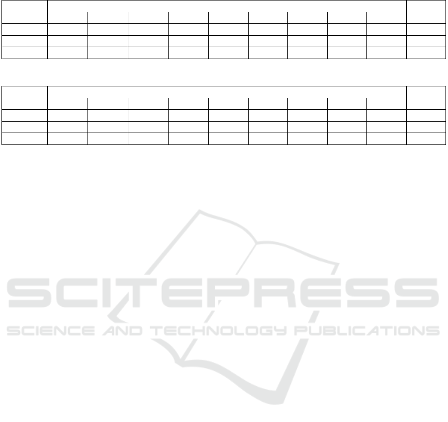
Table 1: Position error (RMSE) for the Avia LiDAR sensor using the Multi-Lidar Multi-UAV dataset (Unit: meter, ∆t: 0.2 s).
MAV
Sequence
Mean
Stnd01 Stnd02 Stnd03 Stnd04 01 02 03 04 05
Holybro 0.05 0.043 0.0446 0.0503 0.0731 0.0992 0.1263 0.0681 0.0777 0.0702
Autel - - - - 0.1313 0.1074 0.1007 0.0845 0.1089 0.1066
Tello - - - - 0.1032 0.0991 0.1223 0.1008 0.0965 0.1044
Table 2: Position error (RMSE) for the Avia LiDAR sensor using the Multi-Lidar Multi-UAV dataset (Unit: meter, ∆t: 0.1 s).
MAV
Sequence
Mean
Stnd01 Stnd02 Stnd03 Stnd04 01 02 03 04 05
Holybro 0.0748 0.0701 0.0612 0.0854 0.0844 0.0837 0.1008 0.0611 0.0802 0.078
Autel - - - - 0.0844 0.0666 0.0713 0.0637 0.0658 0.0703
Tello - - - - 0.0578 0.0489 0.0585 0.0435 0.0493 0.0508
final position. As from cluster detection until now,
a downsampled version of the input cloud has been
used, the accuracy of the estimated position can be
improved. Therefore, based on the estimated position,
the cluster is again extracted from the high resolution
cloud provided by the ground removal part. This clus-
ter now includes edge points that might not have been
considered with the downsampled version. Finally,
the cluster center is calculated using this new cluster.
4 EVALUATION
We evaluate our proposed system in terms of accu-
racy using an MAV dataset (Catalano et al., 2023b)
for comparison with a motion capturing system and a
custom dataset for comparison with the Vive Tracker
system. By using these two datasets, we show that our
system is applicable to MAVs as well as mobile robots
and that it is able to process LiDAR data as well as
regular ToF data. In addition, the custom dataset high-
lights requirements in the system setup.
4.1 MLMU Dataset
The Multi-LiDAR Multi-UAV dataset (Catalano
et al., 2023b) is a dataset designed for detecting and
tracking MAVs using LiDAR sensors. It contains
MAV flights recorded by three different LiDAR sen-
sors, as well as the OptiTrack motion capturing sys-
tem for ground truth data. We only focus on the Livox
Avia sensor. Due to the distance between the sensors
and the MAVs, the point density is too low for the
other two sensors to provide accurate results. This
could be mitigated by reducing the distance between
the sensor and the tracked object, which we were un-
able to test. The three MAVs captured in the dataset
are the Holybro X500, the Autel Evo II, and the Tello.
We omitted the outdoor captures, since we focus on
tracking in indoor environments. Since a single Li-
DAR capture only contains partial information about
the environment, we preprocess the point clouds by
merging them over a certain timespan. We decided
to test the values of ∆t = 0.1 s and ∆t = 0.2 s. The
merged point clouds are published at a frequency of
16 hz in both cases, therefore adding single captures
to multiple point clouds.
The results of our evaluation are shown in Table 1
for ∆t = 0.1 s and in Table 2 for ∆t = 0.2 s. While
the error increased by 11 % with ∆t = 0.1 s for the
Holybro, the results of the Autel and Tello are better
(943 %) with a smaller timespan. While the larger
timespan doubles the point density, we noticed that
higher values leave a point trail, which is especially
noticeable with the smaller MAVs. On the other hand,
while the point density is sufficient for the smaller
MAVs Autel and Tello with ∆t = 0.1 s, at some occa-
sions, the clustering fails for the Holybro, which se-
lects only parts of the MAV and therefore leads to in-
accuracies. Compared to the base results in (Catalano
et al., 2023b), we achieve similar accuracies without
the focus on a specific sensor type. Using only their
evaluated sequences, they perform better on the stan-
dard sequences, possibly due to the use of a kalman
filter, while we achieve a better overall mean error of
0.0589 m compared to their result of 0.0655 m.
4.2 Custom Dataset
The custom dataset has been captured using two pico
Monstar Infrared ToF sensors, with ground truth data
being provided by a Vive Tracker system. The two
sensors have been placed as shown in figure 2 (b),
with the second sensor capturing a side view. The
dataset contains recordings of the mobile robots Pep-
per and Turtlebot 2. An overview of the types of paths
recorded for both platforms is given in Figure 3. Se-
quences 7-8, which are not shown, also include ran-
ICPRAM 2025 - 14th International Conference on Pattern Recognition Applications and Methods
576
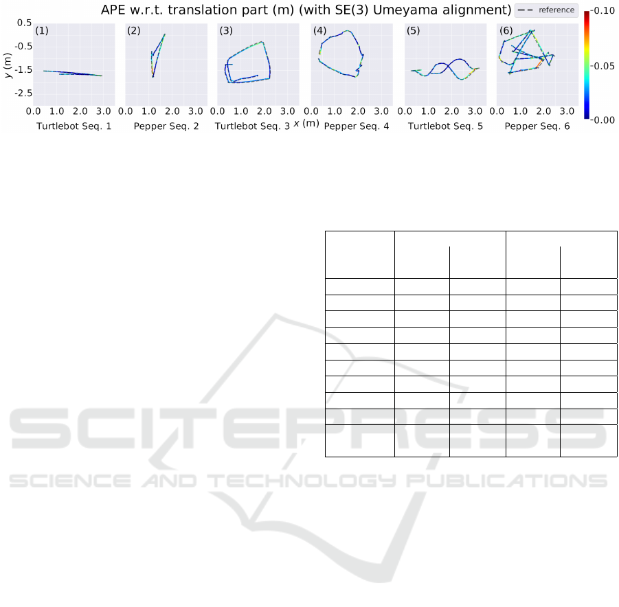
Figure 3: Overview of some of the sequences recorded in the custom dataset for each robot using the Turtlebot and Pepper
robots. The path types include forward-backward (1), left-to-right (2), square (3), circle (4), slalom (5), and random (6).
dom movement with a focus on longer durations, like
in sequence 6. Sequence 0 is a mobile robot standing
still after a small initial forward movement to cap-
ture noise recorded by the sensor. Compared to the
other dataset, this dataset has a stronger focus on the
use case. This includes a smaller distance between
the sensors and the tracked objects for a higher point
density, as well as using two sensors to evaluate the
difference between using one or more sensors. The
individual point clouds have been captured with a fre-
quency of 5 hz and downsampled using a voxel size of
0.02 m. The downsampling is necessary in some cases
to ensure real-time performance, e.g. when the mo-
bile robot is close to the sensor. With smaller robotic
platforms, i.e. MAVs, this might not be necessary.
The results for the custom dataset are shown in Ta-
ble 3. The mean position errors are between 3 cm and
4 cm. The mean error is 10 % higher for the Pep-
per robot. This is due to the more complex shape
compared to the Turtlebot. Furthermore, small un-
controllable upper body movements of the robot can
also negatively impact the accuracy. The results also
show a smaller error of 914 % when using two sen-
sors, as multiple sensors can better capture the full
shape of the tracked object. Note that for sequence
1 (see figure 3a), there is an improvement in accu-
racy using a single sensor, as the second sensor al-
ters the recorded shape of the robotic platform due
to the respective left-right movement leading to inac-
curacies. Another reason for inaccuracies, as can be
seen in figure 3c and 3e, are the accuracy drops on the
outer parts of the tracking area as the visible part of
the robot changes. This is also present with the Pep-
per robot and is amplified through the difference in
shape, when rotating the robot, as shown in figure 3b,
3d, and 3f. The bounding box shape depends on the
orientation, which can lead to a shift in the estimated
center of the robot.
Table 3: Position error (RMSE) for the pico Monstar sensor
using the custom dataset for a single and for two sensors
(Unit: meter).
Sequence
Turtlebot Pepper
Multi-
view
Single-
view
Multi-
view
Single-
view
0 0.0105 0.0054 0.0104 0.0138
1 0.0328 0.0306 0.0364 0.0361
2 0.0284 0.0316 0.0352 0.0429
3 0.0255 0.0305 0.0267 0.035
4 0.0175 0.0209 0.0292 0.0358
5 0.0337 0.0328 0.0284 0.0343
6 0.0289 0.0349 0.0394 0.0461
7 0.0418 0.059 0.0357 0.0463
8 0.04 0.0498 0.0426 0.0412
Mean
(1-8)
0.031 0.0362 0.0342 0.0397
5 CONCLUSION
In this paper, a system for detecting and tracking
robotic platforms for capturing tracking data in lab
environments was presented. The main purpose of
the system is to allow for easy capturing of position
data using already available sensors instead of invest-
ing in a costly motion capturing system. It uses Time-
of-Flight based sensors, like LiDAR, to capture point
clouds. Tracking is already possible using a single
sensor, which allows for a fast setup. Only based
on the dimensions of a model, robotic platforms are
detected in these clouds and their positions are esti-
mated. There is no need to mount additional hardware
or markers onto the robotic platform.
The evaluation shows that the system is capable
of detecting and tracking different robotic platforms
with accuracies in the low-centimeter range using a
single or two sensors and with low double-digit fre-
quencies. While this does not match the accuracies
and frequencies of high-quality motion capturing sys-
tems, we argue that our solution is still applicable
to many use cases. Future work will include an in-
An Easy-to-Use System for Tracking Robotic Platforms Using Time-of-Flight Sensors in Lab Environments
577

tegration of orientation information provided by the
robotic platforms, as well as refinements on the track-
ing accuracy by including the model dimension infor-
mation in the final position estimation. Supplemen-
tary documentation and the source code are available
at https://github.com/IoT-Lab-Minden/RP Tracking.
REFERENCES
Catalano, I., Sier, H., Yu, X., Westerlund, T., and Quer-
alta, J. P. (2023a). Uav tracking with solid-state lidars:
Dynamic multi-frequency scan integration. arXiv
preprint arXiv:2304.12125.
Catalano, I., Yu, X., and Queralta, J. P. (2023b). Towards
robust uav tracking in gnss-denied environments: a
multi-lidar multi-uav dataset. In IEEE International
Conference on Robotics and Biomimetics (ROBIO).
Chen, H., Chen, X., Chuanlong Xie and, S. W., Zhou, Q.,
Zhou, Y., Wang, S., Su, H., and Quanfeng Xu and,
Y. L. (2024). Uav tracking and pose-estimation - te-
chinical report for cvpr 2024 ug2 challenge. In Con-
ference on Computer Vision and Pattern Recognition
(CVPR).
Deng, T., Zhou, Y., Wu, W., Li, M., Huang, J., Liu, S.,
Song, Y., Zuo, H., Wang, Y., Wang, H., and Chen,
W. (2024). Multi-modal uav detection, classification
and tracking algorithm - technical report for cvpr 2024
ug2 challenge. In Conference on Computer Vision and
Pattern Recognition (CVPR).
Dogru, S. and Marques, L. (2022). Drone detection using
sparse lidar measurements. IEEE Robotics and Au-
tomation Letters, 7(2).
Furtado, J. S., Liu, H. H., Lai, G., Lacheray, H., and
Desouza-Coelho, J. (2019). Comparative analysis of
optitrack motion capture systems. In Advances in Mo-
tion Sensing and Control for Robotic Applications.
Gazdag, S., M
¨
oller, T., Filep, T., Keszler, A., and Majdik,
A. L. (2024). Detection and tracking of mavs using
a lidar with rosette scanning pattern. arXiv preprint
arXiv:2408.08555.
Geiger, A., Lenz, P., Stiller, C., and Urtasun, R. (2013).
Vision meets robotics: The kitti dataset. International
Journal of Robotics Research (IJRR).
Giancola, S., Zarzar, J., and Ghanem, B. (2019). Lever-
aging shape completion for 3d siamese tracking. In
IEEE/CVF Conference on Computer Vision and Pat-
tern Recognition (CVPR).
Kaku, K., Okada, Y., and Niijima, K. (2004). Similarity
measure based on obbtree for 3d model search. In In-
ternational Conference on Computer Graphics, Imag-
ing and Visualization (CGIV).
Nie, J., Xie, F., Zhou, S., Zhou, X., Chae, D.-K., and
He, Z. (2024). P2p: Part-to-part motion cues guide
a strong tracking framework for lidar point clouds.
arXiv preprint arXiv:2407.05238.
Pleterski, J.,
ˇ
Skulj, G., Esnault, C., Puc, J., Vrabi
ˇ
c, R.,
and Podr
ˇ
zaj, P. (2023). Miniature mobile robot detec-
tion using an ultralow-resolution time-of-flight sensor.
IEEE Transactions on Instrumentation and Measure-
ment, 72.
Qi, C. R., Yi, L., Su, H., and Guibas, L. J. (2017). Point-
net++: Deep hierarchical feature learning on point sets
in a metric space. arXiv preprint arXiv:1706.02413.
Qi, H., Feng, C., Cao, Z., Zhao, F., and Xiao, Y. (2020).
P2b: Point-to-box network for 3d object tracking in
point clouds. In IEEE/CVF Conference on Computer
Vision and Pattern Recognition (CVPR).
Qingqing, L., Xianjia, Y., Queralta, J. P., and Westerlund, T.
(2021). Adaptive lidar scan frame integration: Track-
ing known mavs in 3d point clouds. In International
Conference on Advanced Robotics (ICAR).
Shule, W., Almansa, C. M., Queralta, J. P., Zou, Z., and
Westerlund, T. (2020). Uwb-based localization for
multi-uav systems and collaborative heterogeneous
multi-robot systems. Procedia Computer Science.
Sier, H., Yu, X., Catalano, I., Queralta, J. P., Zou, Z., and
Westerlund, T. (2023). Uav tracking with lidar as a
camera sensor in gnss-denied environments. In Inter-
national Conference on Localization and GNSS (ICL-
GNSS).
Taffanel, A., Rousselot, B., Danielsson, J., McGuire, K.,
Richardsson, K., Eliasson, M., Antonsson, T., and
H
¨
onig, W. (2021). Lighthouse positioning system:
Dataset, accuracy, and precision for uav research.
arXiv preprint arXiv:2104.11523.
Was¸ik, A., Ventura, R., Pereira, J. N., Lima, P. U., and Mar-
tinoli, A. (2015). Lidar-based relative position esti-
mation and tracking for multi-robot systems. In Robot
2015: Second Iberian Robotics Conference.
Wang, H., Chen, C., He, Y., Sun, S., Li, L., Xu, Y., and
Yang, B. (2024). Easy rocap: A low-cost and easy-to-
use motion capture system for drones. Drones, 8(4).
Wang, H., Peng, Y., Liu, L., and Liang, J. (2021). Study
on target detection and tracking method of uav based
on lidar. In Global Reliability and Prognostics and
Health Management (PHM-Nanjing).
Yilmaz, Z. and Bayindir, L. (2022). Lidar-based robot de-
tection and positioning using machine learning meth-
ods. Balkan Journal of Electrical and Computer En-
gineering, 10(2).
Yuan, S., Yang, Y., Nguyen, T. H., Nguyen, T.-M., Yang, J.,
Liu, F., Li, J., Wang, H., and Xie, L. (2024). Mmaud:
A comprehensive multi-modal anti-uav dataset for
modern miniature drone threats. In IEEE Inter-
national Conference on Robotics and Automation
(ICRA).
Zhou, C., Luo, Z., Luo, Y., Liu, T., Pan, L., Cai, Z., Zhao,
H., and Lu, S. (2022). Pttr: Relational 3d point cloud
object tracking with transformer. In IEEE/CVF Con-
ference on Computer Vision and Pattern Recognition
(CVPR).
ICPRAM 2025 - 14th International Conference on Pattern Recognition Applications and Methods
578
