
Investigation on Microliter Free Jetting Using a Piezoelectric Micro
Pump
Anne Zimmermann
1,2 a
, Jasmin Podlech
1
, Daniel Anheuer
1 b
and Christian Wald
1
1
Fraunhofer EMFT Institute for Electronic Microsystems and Solid State Technologies,
Hansastraße 27d, 80686 Munich, Germany
2
Institute for Smart Electronics and Systems, FAU Erlangen-Nuremberg, Cauerstraße 7, 91058 Erlangen, Germany
{anne.zimmermann, jasmin.podlech, daniel.anheuer, christian.wald}@emft.fraunhofer.de
Keywords:
Piezoelectric Diaphragm Pump, Microliter Dosing.
Abstract:
By avoiding any interaction with surfaces, especially free jetting of liquid pharmaceuticals has numerous
advantages such as no cross-contamination of substances, less waste in pipetting, or the possibility of needle-
free subcutaneous injections. Dispensing a defined amount of a liquid into air without surface contact requires
the formation of a free jet. Therefore, jet generation by a micro pump presents a solution which is versatile in
jet volumes while providing minimal dimensions. Jetting is achieved by the quick actuation of the piezoelectric
actuator on the pump, leading to the ejection of a volume package that is fast enough to overcome the surface
tension at the outlet’s interface, for example a dosing needle. Size and formation of the jet are controlled
by matching the micro pump’s driving parameters such as peak-to-peak voltage and signal waveform. The
feasibility of this setup is tested as well as parameters optimized for free jetting aqueous solution. Furthermore,
the influence of different actuation parameters on the dosing precision is evaluated. A rectangular signal with
250 Hz sine flanks is determined as suitable waveform for the jet generation with the evaluated 20 mm stainless
steel micro pump. Simultaneously, varying and matching the amount of pump strokes and voltage amplitude
results in adjustable dosing volumes.
1 INTRODUCTION
Delivery of small and accurate amounts of liquids is
crucial in several applications. Many of those demand
for a contactless way of applying the medium, for
example to avoid cross-contamination while working
with several liquids. This can be achieved by using a
piezoelectric micro pump in a free jetting setup.
In pipetting, it is necessary to immerse the
pipette’s tip into the medium for aspiration and make
sure that the liquid completely leaves the tip while
dispensing. Therefore, tips are either immersed in a
liquid which is already in the container or need to
touch the container’s wall to overcome capillary ef-
fects (Pushparaj, 2020). Consequently, tips must be
disposed after every dosing cycle. Additionally, one
tip can not be immersed in different containers or
media as it leads to contamination. Instead, a metal
piezoelectric micro pump with a nozzle or dosing nee-
dle generating a free jet can provide a contactless and
waste free solution.
a
https://orcid.org/0009-0009-9364-9178
b
https://orcid.org/0000-0001-7171-6573
In this work, the feasibility of forming an aqueous
free jet using a metal micro pump is shown. There-
fore, parameters such as signal waveform and voltage
are varied to optimize the reliable generation of a jet.
The dosing precision of this technique is evaluated in
a gravimetric setup by comparing the average dosed
volume and the deviation from the median for five
packages. Moreover, it is compared to the dosing pre-
cision of a comparable pump type in a non-free jetting
evaluation from another publication (Thalhofer et al.,
2021). The aim of the first and main part of this pa-
per is to investigate the influence of different driving
parameters on the free jetting performance of a piezo-
electric stainless steel micro pump. The second step
aims to find an optimal parameter set to deliver pre-
cise microliter jets evaluated with a precision scale.
2 MATERIALS AND METHODS
Key devices in the experimental evaluations of this
work are the Fraunhofer EMFT’s 20 mm diameter
stainless steel micro pumps. Additionally, the param-
Zimmermann, A., Podlech, J., Anheuer, D. and Wald, C.
Investigation on Microliter Free Jetting Using a Piezoelectric Micro Pump.
DOI: 10.5220/0013112800003911
Paper published under CC license (CC BY-NC-ND 4.0)
In Proceedings of the 18th International Joint Conference on Biomedical Engineering Systems and Technologies (BIOSTEC 2025) - Volume 1, pages 113-118
ISBN: 978-989-758-731-3; ISSN: 2184-4305
Proceedings Copyright © 2025 by SCITEPRESS – Science and Technology Publications, Lda.
113
eters for jet formation and the jet dosing precision are
gravimetrically evaluated in one measurement setup.
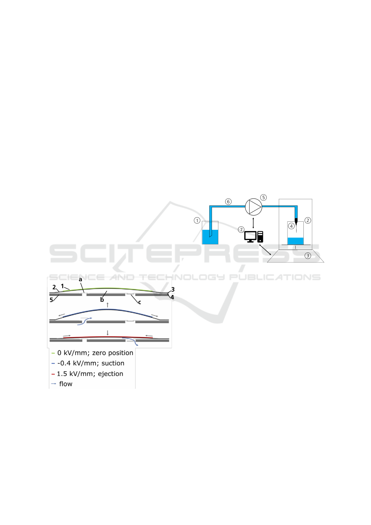
2.1 Piezoelectric Micro Pumps
The steel micro diaphragm pump as shown in Fig-
ure 1 consists of a rigid bottom layer (5) with an in-
let and outlet orifice (Wald et al., 2013). They are
equipped with two valve foils (3+4) and one actuat-
ing diaphragm (2) that are laser welded to the bottom
piece ensuring leak tightness. A round piezoelectric
ceramic (1) is glued to the actuating diaphragm and
pretensioned by applying a voltage during curing of
the glue. Therefore, the pump chamber height bene-
fits from the gluing of the piezoceramic in a curved
state.
Actuation of the pump is established by the in-
verse piezoelectric effect. Alternating voltage signals
lead to contractions and expansions of the piezoce-
ramic thus causing an oscillating movement in the di-
aphragm. The check valves (a+c) in the valve foils
passively open and close, resulting in a unidirectional
pumping movement of the fluid. This working prin-
ciple and the underlying voltages are depicted as zero
position (green), suction (blue), and ejection (red) in
Figure 1 (Bußmann et al., 2021).
The pump evaluated in this paper is of the type
P320009, which describes a stainless steel micro
pump with a 20 mm diameter.
Figure 1: Schematic of the piezoelectric micro pump, con-
sisting of a piezoelectric actuator (1) on an actuator di-
aphragm (2), inlet and outlet valve foil (3+4), and bottom
piece (5). The working priniciple of the pump cycle is de-
scribed by the colors while the fluid flows through the inlet
valve (a), into the pump chamber (b), and out through the
outlet valve (c). Adapted from Bußmann et al. (2021).
2.2 Gravimetric Measurements
All measurement data is obtained using a gravimet-
ric setup as depicted in Figure 2. It consists of an
inlet reservoir filled with distilled water and an out-
let reservoir placed on a precision scale (Sartorius
MC410, resolution 0.01 mg). A dosing needle (ID:
0.41 mm, L: 1.0”, Vieweg GmbH) is installed in a 3D
printed holder fitting into the scale’s chamber, thus
freely suspended above the outlet reservoir to enable
free jetting. Inlet reservoir and dosing needle are flu-
idicly connected via a piezoelectric micro pump by
silicone tubing. Measurement and driving equipment
such as waveform generator, amplifier, and scale are
controlled and logged by a connected computer.
The scale drift and evaporation effects are
emended by additional measurement steps described
in section 2.4.
Figure 2: Schematic of the gravimetric setup: Inlet reser-
voir (1), outlet reservoir (2) on scale (3), dosing needle (4),
micro pump (5), tubing (6), computer control and recording
(7).
2.3 Jet Generation
Different types of jetting techniques and how they can
be generated have already been described in another
publication (Wackerle et al., 2002). Basically, a mini-
mum flow rate must be achieved to overcome the sur-
face tension at an orifice thus forming a jet. Achieving
this using a micro pump, ideally each pump stroke re-
sults in a defined jet. This enables the optimal transla-
tion of the kinetic energy of the diaphragm movement
into the liquids flow rate.
In this publication, the dosed water is distin-
guished in either a detaching droplet or the required
free jet. The difference is quantified visually as
shown in Figure 3 and by comparing the dosed
weights of repeated volume packages. In Figure 3,
the four steps on the left detail a formed droplet, how
it tears off, and falls down from a dosing needle.
In contrast, the right part of Figure 3 depicts the
beginning of a free jet before its tear-off.
BIODEVICES 2025 - 18th International Conference on Biomedical Electronics and Devices
114
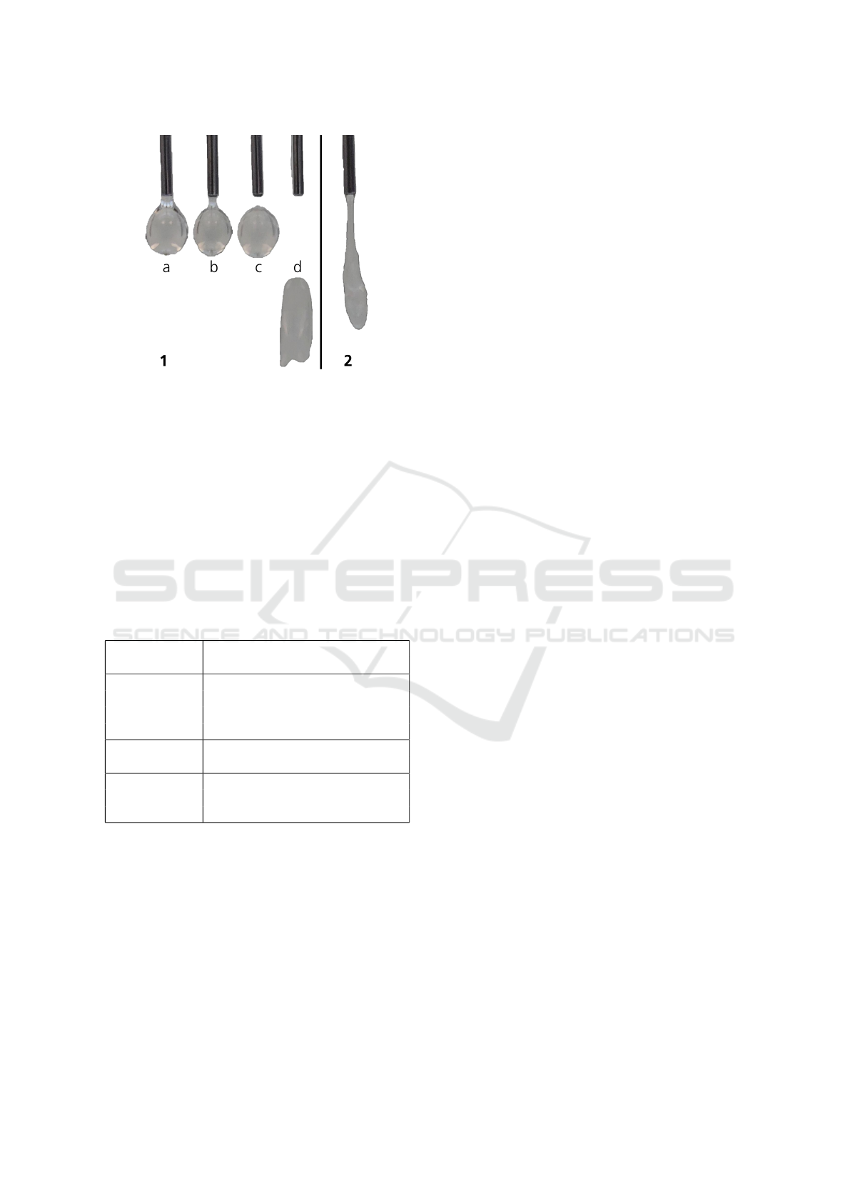
Figure 3: Comparison of droplet detachment (1) and free
jet (2) from a dosing needle. Forming of droplet (a), tear off
(b), droplet falling down (c), and deformation of droplet in
the air (d).
2.4 Methods
A variation of parameters was evaluated in the gravi-
metric setup (see Table 1). Two main measurements
are performed where one is underlying a variation of
the waveform and the other a variation of the peak-
to-peak voltage (Vpp). Both measurements consist of
a sweep through ascending amounts of pump strokes
from one to five.
Table 1: Driving parameter variations.
Actuation Variation
parameter
Waveform Sine wave (SIN)
Rectangular signal (RECT)
Rectangular signal with
250 Hz sine flanks (SRS)
Voltage (Vpp) Positive amplitude:
+100 V to +300 V in 50 V steps
Amount For each waveform & voltage:
of strokes groups of 1, 2, 3, 4, and 5 strokes
(5 volume packages per group)
For the first measurement, three different signal
waveforms were evaluated at a fixed actuator fre-
quency of 10 Hz and voltage amplitude of [+300 V
/ -80 V]. The chosen waveforms were pure sine wave
(SIN) and pure rectangular (RECT) signal, as well as
an artificial rectangular signal with 250 Hz sine flanks
(SRS). Therefore, the first measurement holds three
different waveforms (SIN, RECT, and SRS) with five
groups (1, 2, 3, 4, and 5 strokes) each.
Comparably, the second measurement varies the
positive amplitude of the voltage from +100 V to
+300 V in 50 V steps while the negative amplitude
is fixed to -80 V and frequency at 10 Hz, each vari-
ation with again five groups of stroke amounts. All
groups of the second measurement are driven with a
SRS signal. Every group of both measurements con-
sists of five volume packages with the same driving
parameters to evaluate their precision.
Each volume package is sampled by ten scale
measurement points. Five measurement points are
recorded before the dosing of the previously defined
package. Five more points are recorded after a six
second waiting period after the package was trig-
gered.
The dosed weight per package is calculated by
subtracting the average of the five points before the
trigger from the average of the five points after the
trigger. This allows to reflect the dosed weight with-
out influences from a potential scale drift due to evap-
oration effects.
Calculating the volume per pump stroke or per
package from the measured weight can be done by
multiplying it with the density of water (0.998 kg*m
-3
at 23 °C).
3 RESULTS
The driving parameters of the metal pump are var-
ied as previously described to optimize their precision
in microliter range free jetting. First, different wave-
forms are evaluated while the pump is driven in burst
mode enabling the control of volume package groups
of 1, 2, 3, 4, and 5 strokes per waveform, respectively.
This burst mode allows the triggering of exactly one
stroke in the period of the signal, starting with the
negative amplitude and ending at the end of the posi-
tive amplitude. This guarantees a signal related reso-
lution of the stroke instead of a time-resolved trigger
leading to random starting points of a burst within the
signal’s period.
For the sinusoidal signal (see Figure 4), package
volumes are at 3.34 mg ± 4.95 mg for one stroke,
whereas for 2, 3, 4, and 5 strokes volume packages
show 5.24 mg ± 2.41 mg, 9.82 mg ± 1.17 mg, 13.66
mg ± 1.07 mg, and 17.65 mg ± 1.08 mg, respec-
tively. Thereby, the largest deviation from the median
is visible for the 1-stroke packages where for three
out of five packages no water is delivered onto the
scale. The measured volume packages per waveform
are also visible in the first column of Table 2.
Improvements are seen for the actuation with a
rectangular signal in Figure 5. For this signal average
deviations from the median are in the range of 1.85
mg. At the same time, the largest difference between
the smallest and highest dosed volume package per
Investigation on Microliter Free Jetting Using a Piezoelectric Micro Pump
115
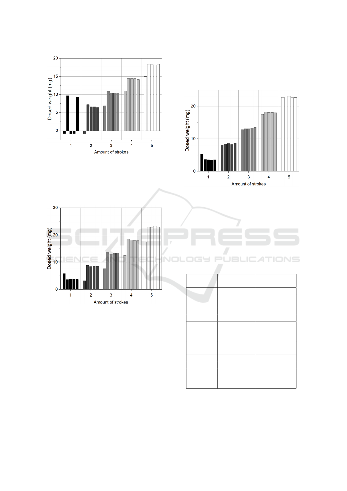
Figure 4: Dosed weight per package in groups of 1, 2, 3, 4,
and 5 strokes for a sinusoidal signal. Five repeated packages
per group.
group is 6.20 mg, as the first package in the 3-stroke
group yields 7.60 mg and the other four packages are
above 13.03 mg.
Figure 5: Dosed weight per package in groups of 1, 2, 3, 4,
and 5 strokes for a rectangular signal. Five repeated pack-
ages per group.
The SRS signal in Figure 6 has only ±0.53 mg
maximal deviation from the median for the five pack-
ages. The bar graphs for sine and rectangular sig-
nal show that the first dosed package of each group
of the same number of strokes is different from the
other four, thus mostly resembling the volume of the
previous group. This indicates an incorrect signal
trigger when switching the stroke settings from one
group to the next which is verified by an oscilloscope
measurement of the rectangular input signal. The
recorded signal shows exemplary five times four trig-
gered strokes. During the switch from four to five
strokes, there is an aperiodic stroke with only half of
the required voltage amplitude. Consequently, the fol-
lowing first package out of the group with five strokes,
only shows four. This wrong trigger is observed for
every switch between groups for the sine and rectan-
gular signals.
Figure 6: Dosed weight per package in groups of 1, 2, 3, 4,
and 5 strokes for a SRS signal. Five repeated packages per
group.
Therefore, the first package of each group is re-
moved and the average deviation from the median is
recalculated for the remaining four packages. This
leads to an improvement of the median deviation in
nearly all groups independent of the waveform. The
corrected values are summarized in the second col-
umn of Table 2.
Table 2: Dosed weight before and after correction.
Waveform Dosed Dosed weight
weight (mg) corrected (mg)
SIN 3.34 ± 4.95 4.37 ± 5.16
5.24 ± 2.41 6.75 ± 0.24
9.82 ± 1.17 10.55 ± 0.19
13.66 ± 1.07 14.33 ± 0.08
17.65 ± 1.08 18.32 ± 0.08
RECT 4.10 ± 0.70 3.67 ± 0.01
7.48 ± 1.72 8.56 ± 0.13
12.22 ± 1.85 13.37 ± 0.21
17.04 ± 1.82 18.17 ± 0.16
21.89 ± 1.76 22.99 ± 0.13
SRS 3.93 ± 0.53 3.59 ± 0.04
8.40 ± 0.16 8.47 ± 0.13
13.20 ± 0.20 13.31 ± 0.15
18.03 ± 0.20 18.15 ± 0.06
22.83 ± 0.14 22.85 ± 0.15
The second parameter that is examined is the volt-
age amplitude. Therefore, the negative voltage of -
80 V is fixed while varying the positive voltage from
+100 V to +300 V in 50 V steps. Figure 7 shows
BIODEVICES 2025 - 18th International Conference on Biomedical Electronics and Devices
116
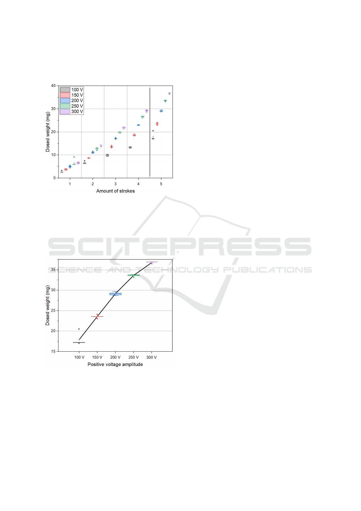
that the overall volumes per stroke are increasing for
increasing voltages with mostly linear behavior be-
tween the ascending amounts of strokes.
Figure 7: Dosed weight of 1, 2, 3, 4, and 5 strokes. Every
group with ascending 100 V, 150 V, 200 V, 250 V, and 300 V
positive driving voltage amplitude. Negative voltage fixed
to -80 V.
The average volume for one stroke at +100 V was
2.67 µl ± 0.25 µl (first box of group 1 in Figure 7) and
6.57 µl ± 0.31 µl for +300 V actuation voltage (fifth
box in group 1), thus 2.5 times more.
Figure 8: Detailed view of the dosed weight of 5 bursts for
100 V, 150 V, 200 V, 250 V, and 300 V.
Accordingly, the relationship between the voltage
amplitude and stroke volumes is also almost linear,
but slightly decreasing toward 250 V and 300 V as vi-
sualized in Figure 8. It shows group 5 from Figure 7
in detail. In this group, 5 bursts are dosed with pos-
itive voltage amplitudes of 100 V, 150 V, 200 V, 250
V, and 300 V, respectively. The mean of each box is
connected for better visualization. It emphasizes the
linear correlation of the first three voltage packages
and the decline of the last two. Moreover, the devia-
tion and outliers from the mean are decreasing toward
higher voltage values. Similar behavior is observed in
all groups, independent of the underlying amount of
bursts.
4 DISCUSSION
The formation of a free jet using a piezoelectric micro
pump is achieved and the dosing of different volumes
is accomplished by combinations of voltage ampli-
tudes and amount of strokes. In addition, the wave-
form of the driving signal has an influence on jet gen-
eration.
As already described in the publication of Thal-
hofer et al. (2021), the flanks of the signal must be
sufficiently steep to provide defined volume pack-
ages. The aim of Thalhofer’s publication was to eval-
uate the dependency of the dosed volume on signal
shape, amplitude, and frequency but in a non-free jet-
ting setup (Thalhofer et al., 2021). Consequently, the
dependency of the described flank steepness is even
more crucial in our paper, concentrating on a free jet
creation. In addition to the delivery of defined vol-
ume portions per stroke in both setups, droplet de-
tachment in the free jetting setup is also influenced by
the kinetic energy of the liquids during a pump stroke
which is based on the steepness of the signal flanks
(Wackerle et al., 2002).
For the sinusoidal signal, specifically the recorded
weights for one stroke, only two out of five packages
are measured on the scale indicating that a droplet at
the needle’s tip is formed without falling down. This
droplet formation was observed during the operation
of the measurements. This indicates that the flanks
are not sufficiently steep in the sine signal, resulting
in a gradually growing droplet. Only reaching a spe-
cific size and weight and the impulse of another pump
stroke cause it to detach and fall. The inconsistency
in the measured packages of group 1 in Figure 4, sup-
ports this correlation.
Instead, the required free jetting behavior for a
predictable volume per package is achieved by pro-
viding a certain velocity of the liquid for every stroke.
This leads to the formation of a defined jet instead
of droplets accumulating at the dosing needle’s tip.
Therefore, combinations of different voltage ampli-
tudes and signal waveforms provide steeper flanks,
thus higher liquid velocity and more precise jets. As
sharp signals can have an effect on the pump’s me-
chanical properties and lifetime, the rectangular sig-
Investigation on Microliter Free Jetting Using a Piezoelectric Micro Pump
117

nal with 250 Hz sine flanks is preferred over the pure
rectangular signal.
In another publication, a similar micro pump de-
sign was introduced to enable the delivery of high
viscosity liquids (Surendran et al., 2024). It was
equipped with a piezoelectric stack actuator, thus al-
lowing high pressure actuation while limiting the volt-
age to 200 V. Surendran et al. (2024) also observed
degradation of pump functionality due to actuation
with a rectangular signal, although the overall voltage
amplitude was smaller.
The non-free jetting single-stroke volumes from
Thalhofer et al. (2021) yield 11.1 µl ± 0.1 µl for a
voltage amplitude of [+300 V / -80 V], SRS signal,
and pump stroke frequency below 20 Hz. In the free
jetting setup of our publication, single-stroke volumes
with the same parameters, and fixed frequency of 10
Hz, are at 3.59 µl ± 0.04 µl and 6.57 µl ± 0.32 µl
for the first and second measurement, respectively.
Smaller volumes in the free jetting results, compared
to greater values in Thalhofer et al. (2021), can be
explained by fluid that remained in the tubes or at
the needle’s tip. Moreover, even though the exact
same pump type is used in the compared publica-
tions, each pump within one pump type can be dif-
ferent due to production. However, the results for the
first and second measurement of this paper are dif-
ferent for the same parameters and the same pump
evaluated. Therefore, small differences in the setup
can highly influence the dosed volume. In this pub-
lication, the deviation of the average dosed weight is
used as an indicator for the precision of dosing with
the micro pump. A positive finding is that the devia-
tion for dosed volumes in jetting and non-jetting se-
tups is overall below 5% for the previously described
parameters.
For both publications, it was observed that the
dosed portions for the sinusoidal signal always show
less volume than the SRS packages (Thalhofer et al.,
2021).
5 CONCLUSION
Jet dosing with stainless steel micro diaphragm
pumps is realized and yields reliable minimal jet vol-
umes of 3.59 µl and 3.66 µl for the actuation with a
[+300 V / -80 V] SRS and rectangular signal, respec-
tively. Therefore, they can be implemented in prod-
ucts requiring defined volumes like pipettes.
As the previous comparison of jetting and non-
jetting precision shows very different results due to
comparing different pumps, future research will focus
on the differences of jetting and non-jetting by com-
paring free jet and standard dosing results of the same
pump.
Additionally, it is important to find a method to
characterize and calibrate the presented micro pumps,
as stroke sizes are varying from pump to pump. More-
over, the feasibility of microliter jetting of higher vis-
cose mediums will be investigated to prepare the us-
age of micro pumps in dosing of complex pharmaceu-
ticals.
The results presented in this paper, can enable the
development of a new pipetting technique. The mi-
cro pump provides a jet with a defined volume that
can be delivered contactless into a container, making
the use of disposable pipetting tips obsolete. For this
application, the robustness of free jet microliter dos-
ing using a micro pump must be improved. Replacing
the current single-layered piezoelectric actuator wit a
stack actuator as described by Surendran et al. (2024),
can be beneficial for precision and robustness of free
jetting. Moreover, energy consumption and dosing
volumes can be reduced while achieving liquid jets
with higher velocity, pressure, and viscosity. This can
enable the application of micro pumps in needle-free
subcutaneous injections.
REFERENCES
Bußmann, A. B., Durasiewicz, C. P., Kibler, S. H. A., and
Wald, C. K. (2021). Piezoelectric titanium based mi-
crofluidic pump and valves for implantable medical
applications. Sensors and Actuators A: Physical, page
112649.
Pushparaj, P. N. (2020). Revisiting the micropipetting tech-
niques in biomedical sciences: A fundamental pre-
requisite in good laboratory practice. Bioinformation,
16(1):8–12.
Surendran, N., Durasiewicz, C. P., Hoffmann, T., Wille, A.,
Bussmann, A. B., and Richter, M. (2024). Microflu-
idic delivery of high viscosity liquids using piezo-
electric micropumps for subcutaneous drug infusion
applications. IEEE Open Journal of Engineering in
Medicine and Biology, 5:21–31.
Thalhofer, T., Bussmann, A. B., Durasiewicz, C. P., and
Hayden, O. (2021). Effect of actuation signal on sin-
gle stroke volume in metal micro diaphragm pumps.
International Conference and Exhibition on New Ac-
tuator Systems and Applications.
Wackerle, M., Drost, A., and Richter, M. (2002). A novel
device for high frequency ejection of nanoliter jets:
Actuator, international conference on new actuators,
8, international exhibition on smart actuators and drive
systems, 2, 2002, pp.227-230.
Wald, C., Richter, M., Holzer, M., and Weigl, M. (2013).
Concept of a novel stainless-steel micro pump for ap-
plications in medicine and biotechnology. Mikrosys-
temtechnik Kongress 2013.
BIODEVICES 2025 - 18th International Conference on Biomedical Electronics and Devices
118
