
Simulation and Evaluation of Thermal Effects Under MRI for
Cochlear Implants
Yuanling Ma
1
, Dian Yang
2
, Liping Qin
3
, Xuesong Ye
4a
and Congcong Zhou
5b
1
Biosensor National Special Laboratory, Key Laboratory of Biomedical Engineering of Ministry of Education,
College of Biomedical Engineering and Instrument Science, Zhejiang University, Hangzhou, 310027, China
2
Zhe Jiang Key Laboratory of Intelligent Rehabilitation and Translational Neuroelectronics, China
3
Zhejiang Institute of Medical Device Supervision and Testing, China
4
National Engineering Research Center for Innovation And Application of Minimally Invasive Instruments,
College of Biomedical Engineering and Instrument Science, Zhejiang University, Hangzhou, 310027, China
5
National Engineering Research Center for Innovation And Application of Minimally Invasive Instruments
,
Sir Run Run Shaw Hospital, School of Medicine, Zhejiang University, China
Keywords: RF-Induced Heating, Finite Element Method, Cochlear, Electromagnetic Safety.
Abstract: Cochlear implantation is a widely used rehabilitation method for severe sensorineural deafness, but MRI scans
can induce RF heating in implants, posing safety risks to patients. In this study, a novel finite-element-based
electromagnetic and thermal coupled simulation method to obtain the temperature distribution and maximum
temperature rise due to RF-induced heating is studied. This method allows for a quick analysis of the worst-
case implant configurations and an evaluation of RF heating effects. Additionally, for cochlear implants, we
propose a refined model parameters setting method which using a localized cochlear phantom in simulations
to analyse key factors affecting RF-induced heating include electrode length, lead trajectory, and phantom
model. In this paper, RF heating was evaluated using two phantoms, three electrode lengths, and three typical
lead trajectories, with the highest temperature rise observed at 1.922°C in the cochlear phantom. The results
show that small variations in electrode length have less impact compared to wire trajectory and phantom
model, indicating the need for greater focus on these factors when assessing RF heating in active implants.
1 INTRODUCTION
Deafness is one of the most prevalent disabling
conditions worldwide. The World Health
Organization (WHO) estimates that hearing
impairment costs the global economy approximately
$750 billion annually. Among the primary causes of
deafness is severe to profound hearing impairment,
which leads to disabling hearing loss (Chadha et al.,
2021). For patients with severe or profound
sensorineural deafness, cochlear implantation
remains the only effective method of
rehabilitation(Buchman et al., 2020). The increasing
necessity for MRI in cochlear implant users demands
rigorous safety assessments(Alberalar et al., 2023),
with RF-induced heating being a pivotal area of
focus.
a
https://orcid.org/0000-0002-3439-3733
b
https://orcid.org/0000-0001-8397-1491
Magnetic resonance imaging (MRI) is a widely
used diagnostic tool in clinical practice due to its
numerous advantages. It is non-invasive, free of
ionizing radiation, and can visualize internal
structures like the heart and blood vessels without the
use of contrast agents. MRI also offers high-
resolution imaging of soft tissues, minimal
interference from bone artifacts, and multidirectional
and multiparametric imaging capabilities(Koptyug et
al., 2023). However, the increasing strength of MRI
magnetic fields, combined with the advancement of
new MRI technologies, has raised concerns regarding
the biological effects and safety of MRI, particularly
for patients with medical implants. The high-power
radiofrequency (RF) coils used in MRI systems can
induce electromagnetic resonance in conductive
implants, leading to RF-induced heating, which may
Ma, Y., Yang, D., Qin, L., Ye, X. and Zhou, C.
Simulation and Evaluation of Thermal Effects Under MRI for Cochlear Implants.
DOI: 10.5220/0013113400003911
Paper published under CC license (CC BY-NC-ND 4.0)
In Proceedings of the 18th International Joint Conference on Biomedical Engineering Systems and Technologies (BIOSTEC 2025) - Volume 1, pages 119-125
ISBN: 978-989-758-731-3; ISSN: 2184-4305
Proceedings Copyright © 2025 by SCITEPRESS – Science and Technology Publications, Lda.
119

cause irreversible tissue damage, such as burns. This
is especially concerning for patients with implants
located near sensitive areas, like the brain(Rezai et al.,
2002). Cochlear implants, positioned subcutaneously
behind the ear and close to the brain, are particularly
susceptible to this risk, making RF-induced heating a
critical safety issue that requires thorough testing.
Previous studies primarily focused on in vivo
testing, a method involving the implantation of
devices into animals or human subjects, followed by
the monitoring of physiological parameters in an MRI
environment. Crane et al. conducted a retrospective
analysis of the safety and diagnostic validity of
cochlear implants in patients undergoing MRI
scans(Crane et al., 2010). However, their study was
limited by the absence of quantitative measurements
and a lengthy experimental timeline. Additionally,
Luechinger et al. evaluated the RF safety of cochlear
implants in experimental pigs (Long White breed),
while Roger et al. assessed the radiofrequency safety
of pacemaker leads in Danish Long White
pigs(Luechinger et al., 2005). Despite these efforts,
the in vivo approach was constrained by the
limitations of measuring locations and difficulties in
obtaining precise data.
To ensure standardization, avoid potential
medical ethical issues, and improve experimental
convenience, the ASTM F2182 standard outlines a
test procedure in which the implant is embedded in a
gelatinized saline-filled body phantom, exposed to an
RF field with a whole-body average specific
absorption rate (SAR) of 2 W/kg using a benchtop
system. The temperature is monitored for 15 minutes,
and the local SAR is determined using a calorimetric
method(ASTM_International, 2019). Yang et al.
found that, for devices implanted in or near bone
tissue, the assessment of RF-EMF energy deposition
using an ASTM model that incorporates bone
provided a better correlation with human models
compared to the standard ASTM model(Yang et al.,
2024). However, despite the widespread use and
study of in vitro body models for RF heating
evaluations, significant limitations remain. The
human body is a complex, heterogeneous
environment composed of various tissues, and the
homogeneous gel-saline models used cannot
sufficiently mimic the diverse properties of human
tissues to accurately reflect the heating effects of
implants in such a complex biological
environment(Ran et al., 2017).
The ISO/TS 10974:2018 standard outlines a four-
layer test methodology designed to account for the
wide range of configurations and applications of
active implantable medical devices (AIMDs), aiming
to provide a conservative estimate of energy
deposition in controlled in vitro test systems
(Standardization, 2018). Numerous studies have also
employed the Finite-Difference Time-Domain
(FDTD) method and transfer function approach to
assess RF-induced heating. For example, Zeng et al.
evaluated RF heating in a cochlear implant within a
1.5T MRI coil using the FDTD method, alongside a
virtual human body model for electromagnetic
simulation, and employed the transfer function
approach to estimate temperature rise. They also
explored variables such as lead type, trajectory, and
MRI parameters on RF heating effects(Zeng et al.,
2018). Similarly, Islam et al. investigated RF-induced
heating in partially inserted electrodes in 1.5T MRI
systems, revealing that heating was significantly
influenced by factors such as contact size, spacing,
lead length, and clinically relevant trajectories(Islam
et al., 2023). While this approach has become widely
adopted due to its ability to maintain the complexity
of the implant system’s microstructure, it has some
limitations. The accuracy of FDTD EM simulations
is moderate, and the measurement of transfer
functions requires physical prototypes, making
repeated testing time-consuming and less suitable for
implants with complex and variable wire geometries,
such as cochlear implants. In such cases, alternative
methodologies may offer better efficiency and
precision(Winter et al., 2021).
The assessment of RF-EMF safety requires
consideration of curved components such as birdcage
coils and implant electrodes. In this context, the Finite
Element Method (FEM) emerges as an optimal
approach, offering enhanced precision in analyzing
complex, curved geometries compared to other
techniques(Winter et al., 2021). This paper introduces
a combined electromagnetic and temperature field
simulation method, based on the FEM approach, to
evaluate RF-EMF-induced heating in a cochlear
implant system within a 1.5T MRI coil. The method
facilitates the assessment of heating effects on the
cochlear implant system and investigates the key
factors influencing these thermal effects.
2 MATERIALS AND METHODS
2.1 Cochlear Implants
The contemporary generation of cochlear implants
consists of two principal components: the implant and
an external sound processor. The electrode array in
modern cochlear implants typically contains 12 to 22
electrodes, although the exact number may vary
BIODEVICES 2025 - 18th International Conference on Biomedical Electronics and Devices
120
depending on device design and specific clinical
requirements. This array, approximately 2 cm in
length, is connected to one or more internal current
sources, which are activated based on commands
from the external device(Macherey & Carlyon, 2014).
The external sound processor, worn behind the ear, is
removable and can be detached during magnetic
resonance imaging (MRI) examinations. As a result,
this study focuses exclusively on the radiofrequency
electromagnetic field RF-induced heating of the
implant portion.
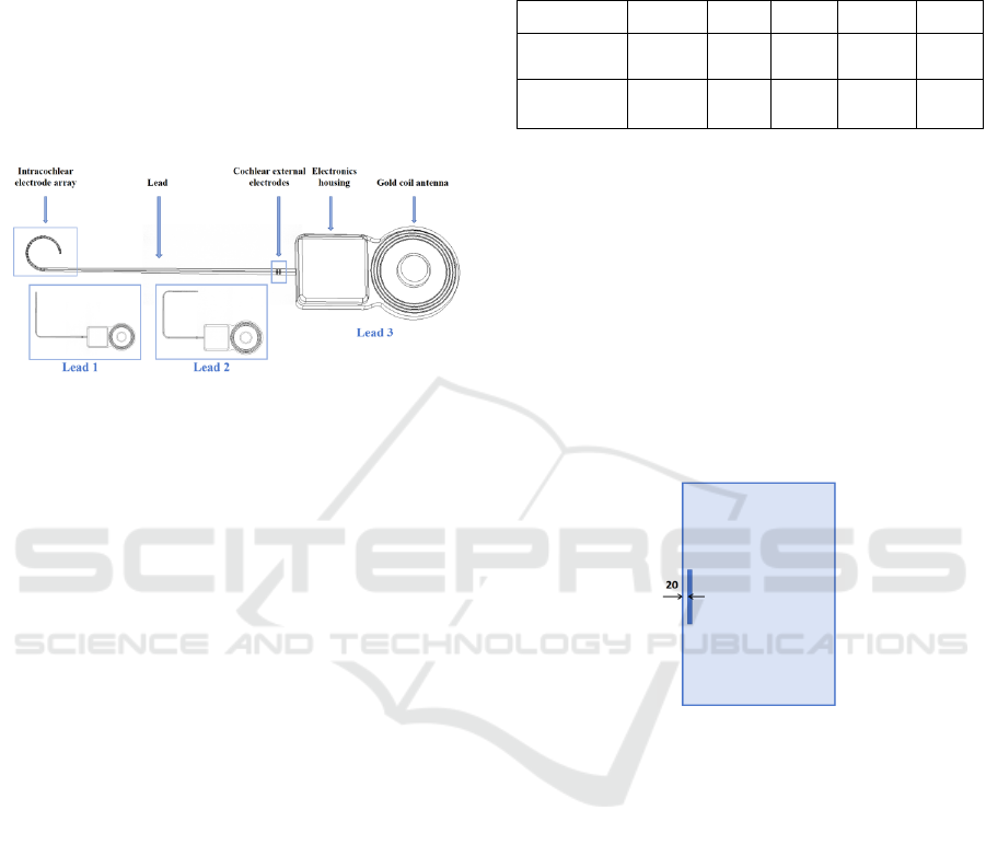
Figure 1: Representative configurations of cochlear
implant.
As illustrated in Figure 1, a typical cochlear
implant designed by Nurotron comprises consists of
several key components, including the intracochlear
electrode array, lead, extracochlear electrodes,
electronic housing, and gold coil antenna. The
intracochlear electrode array is depicted as a 24-
electrode cylinder with radii of 0.4 mm, 0.5 mm, and
0.6 mm, respectively, tapering towards the tip of the
lead. To accommodate the anatomical variation of the
patient’s cochlea and case-specific requirements, the
length of the electrode array can be selected from 17.5
mm, 22.0 mm, or 25.5 mm. Additionally, two
extracochlear electrodes are also implemented in the
system.
2.2 Phantom for Cochlear Implants
The ASTM phantom was used in place of the human
body for the simulation. Since the cochlear implant is
typically implanted in the human cochlea, and the
main components of the cochlear environment
include the cochlear canal as well as internal and
external lymphatic fluids(Fatani et al., 2024), a
configuration simulating the cochlear environment
was incorporated. The specific parameters of this
configuration are presented in Table 1
(Hasgall PA, 2024), where
r
ε is the relative dielectric
constant,
(unit : S / m)σ is the conductivity,
2
k(unit : W / (m K))⋅
is the coefficient of thermal
conductivity,
c(unit : J / (kg K))⋅ is the heat capacity,
3
(unit : kg / m )ρ
is the density.
Table 1: Material parameters.
Phantom
r
ε
σ
k c ρ
ASTM
p
hanto
m
80 0.47 0.57 4150 1050
Cochlear
p
hanto
m
57.75 0.32 0.46 3226 1089
The location and trajectory of the cochlear
implant within the ASTM phantom are illustrated in
Figure 2. The implant is positioned at the center of the
ASTM phantom, 45 mm from both the top and
bottom of the gel, aligned with the aperture direction,
and 2 cm from the sidewalls, where a relatively high
and evenly distributed electric field exists. Given that
RF-induced heating of partially inserted electrodes is
closely correlated with clinically relevant
trajectories(Islam et al., 2023), and cochlear
implantation often involves electrode bending, this
paper discusses several typical simplified cochlear
bending trajectories.
Figure 2: The position and dimension of inserted bone
structure. Unit: mm.
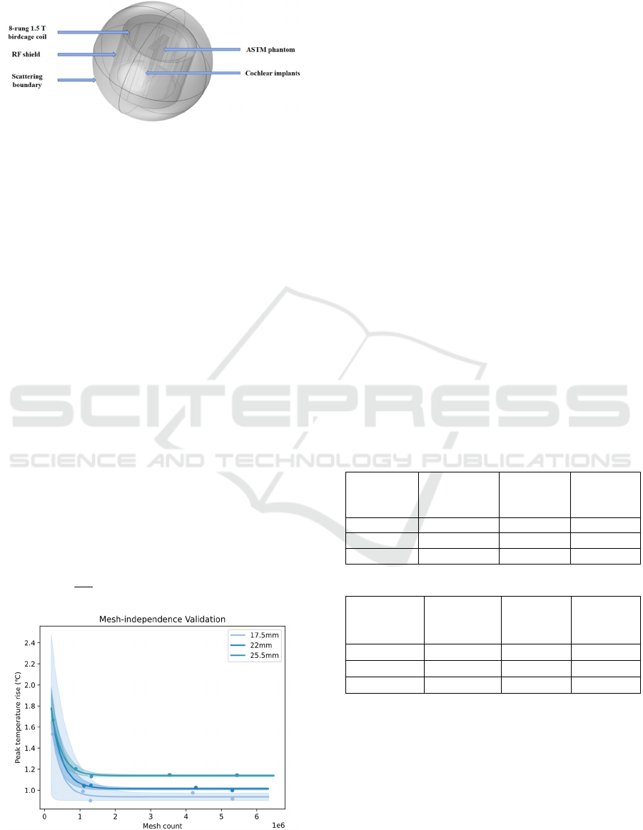
2.3 Coupled EM and Thermal
Simulations
An 8-rung 1.5T low-pass birdcage coil (diameter: 800
mm, length: 700 mm) was used to generate a
circularly polarized electromagnetic field, driven in
quadrature mode at 64 MHz. The ASTM phantom
with the implant was positioned such that the center
of the phantom aligned with the isocenter of the RF
coil. To ensure proper electromagnetic isolation and
stable tuning, an RF shield was integrated around the
exterior of the birdcage coil. Scattering boundary
conditions were applied to truncate the computational
region, effectively simulating real-world conditions.
The initial value of the capacitance was estimated
using the Birdcage Builder Software developed by
Penn State University(Chin et al., 2002). A
subsequent scanning search was conducted in the
Simulation and Evaluation of Thermal Effects Under MRI for Cochlear Implants
121
vicinity of this value to determine the optimal
capacitance, which was approximately 12.3 pF.
Figure 3: Illustration of simulation setup, the position of
various components.
A sequential coupled electromagnetic and thermal
analysis was performed using the Finite Element
Method (FEM) simulation software COMSOL
Multiphysics to calculate the electric and temperature
fields for the ASTM phantom cochlear implant model.
Maxwell's equations were employed to solve the
fluctuating electromagnetic fields at specific points
within the model, influenced by the electromagnetic
field under investigation, in the steady-state
frequency domain. The steady-state electromagnetic
solution of Maxwell's equations provided the heat
source for the transient thermal analysis, which
yielded the electromagnetic solution for all domains
and the heat transfer solution within the ASTM body
model and the implant. Using the SAR as the heat
source for the temperature rise, the temperature field
distribution within the model is obtained by solving
the heat conduction equation through the Finite
Element Method (FEM), as shown in Eq. (1), where
ρ
is the density of the phantom, c is the specific heat
capacity of the phantom,
k is the thermal diffusivity,
T
is the temperature at a point in space,
t
is time and
Q
is the heat source.
22
∂
ρ=∇+=∇+
∂
T
ckTQkTSAR
t
(1)
Figure 4: Illustration of mesh-independence validation.
A non-uniform mesh was utilized in the simulation,
with the mesh density near critical inflection points
selected as the final simulation mesh based on mesh-
independence validation. This approach reduced
computational costs while maintaining accurate
modelling.
3 RESULTS AND DISCUSSION
All results were obtained through numerical
simulations using the methodology described above,
with the input power of RF coil normalized to a
whole-body average SAR of 2 W/kg, in accordance
with the IEC 60601-2-33 power limitation criterion
for the MR normal mode of operation(Commission,
2022). This study evaluates RF-induced heating in
two phantoms with three different electrode lengths
and three typical simplified cochlear implant bending
trajectory scenarios. This study will analyze the RF-
induced heating by examining the spatial and
temporal distribution and variation of temperature. It
will focus on potential factors affecting maximum
temperature rise, including electrode length, lead
trajectory, and phantom models.
Table 2: Statistical analysis of temperature rises in phantom
around the lead tip under all the studied exposure
conditions. (Unit:℃)
(a) ASTM phantom
Bending
trajectories
17.5mm
electrode
length
22mm
electrode
length
25.5mm
electrode
length
Lead 1 1.458 1.459 1.461
Lead 2 1.589 1.629 1.746
Lead 3 1.592 1.592 1.597
(b) cochlear phantom
Bending
trajectories
17.5mm
electrode
length
22mm
electrode
length
25.5mm
electrode
length
Lead 1 1.456 1.479 1.518
Lead 2 1.736 1.793 1.898
Lead 3 1.906 1.921 1.922
The statistical results of all simulations are
presented in Table 2. In the ASTM phantom, the
maximum temperature rises for Lead 1, Lead 2, and
Lead 3 were 1.461°C, 1.746°C, and 1.594°C,
respectively. A similar trend was observed in the
cochlear model, where the maximum temperature
rises were 1.518°C, 1.898°C, and 1.956°C for Lead 1,
Lead 2, and Lead 3, respectively. For a given
trajectory, the maximum temperature rise was
BIODEVICES 2025 - 18th International Conference on Biomedical Electronics and Devices
122

consistently higher in the cochlear phantom
compared to the ASTM phantom.
3.1 Temperature Rise Distribution
By analyzing the spatial distribution of temperature
rise, based on the model's exposure to RF
electromagnetic fields for 15 minutes, as shown in Fig.
5, it can be concluded that in several scenarios
examined in this study, the areas with the highest
temperature increases are concentrated at the ends of
the gold coil, the outer cochlear electrode, and the tip
of the inner cochlear electrode. The hotspot is
primarily located at the tip of the inner cochlear
electrode, which warrants focused attention in further
research. Theoretically, the implant can be considered
an RF antenna that captures energy along its length
and dissipates the maximum energy density near its
end(Pozar, 2021), which aligns with the observed
hotspot at the tip of the intracochlear electrode.
Figure 5: Distribution of temperature rise around the
implant after 15 minutes of exposure.
Figure 6: Temperature rise curves for the maximum
temperature rise case for three bending trajectories.
In the time domain, the temperature rise curve
shown in Fig. 6 exhibits a rapid, near-linear increase,
followed by a gradual leveling off. The rate of
temperature change over time depends on the balance
between the power density absorbed from the RF
source and heat conduction within the phantom
material. As the temperature rise becomes significant,
heat conduction begins transferring heat from the
implant to the surrounding material, which slows the
rate of further temperature increase.
3.2 Electrode Length
Temperature rises were calculated for three electrode
lengths in both ASTM and cochlear phantoms to
investigate the effect of electrode length on RF-
induced heating. The electrode lengths, chosen based
on recommendations from implant surgeons, were
17.5 mm, 22.0 mm, and 25.5 mm to accommodate
different cochlear anatomical structures and case
variations. The type and number of electrodes
remained consistent across lengths, with the primary
difference being the spacing between electrodes. The
mean RF-induced temperature rises for electrode
lengths of 17.5 mm, 22.0 mm, and 25.5 mm were
1.546°C, 1.560°C, and 1.600°C in the ASTM
phantom, and 1.699°C, 1.743°C, and 1.779°C in the
cochlear phantom. As illustrated in Figure 7(a), the
maximum temperature rise tended to increase with
longer electrode lengths in both phantoms.
Figure 7: (a) Line graph showing the average maximum
temperature rise for different electrode lengths in both the
ASTM and cochlear phantoms, (b) line graph showing the
maximum temperature rise for different bending
trajectories in both the ASTM and cochlear phantoms.
When the implant's size is approximately half the
wavelength, a significant temperature rise occurs due
to the resonance effect(Konings et al., 2000). This
resonance phenomenon is heavily influenced by the
electrical properties and the operating frequency of
the medium surrounding the implant. Neglecting
magnetic permeability, the wavelength of an
electromagnetic wave
λ
m
in a given material can be
calculated using Eq. (2), where
0
λ
is the wavelength
of the electromagnetic wave in vacuum and
ε
r is the
relative dielectric constant.
0
λ
λ
ε
=
m
r
(2)
Simulation and Evaluation of Thermal Effects Under MRI for Cochlear Implants
123

The wavelength of an electromagnetic wave in a
vacuum
0
λ
is related to the RF frequency. In this
study, the research focuses on the 1.5T case.
According to Eq. (3), the wavelength can be
calculated as approximately 4.6875m.
0
λ
=
c
f
(3)
The relative permittivity of the ASTM phantom is
80, while that of the cochlear phantom is 57.75. Using
these values and applying Eq. (2), the theoretical half-
wavelengths are calculated as 26.20 and 30.84mm,
respectively, for ASTM and cochlear phantom. The
cochlear implant leads tested thus far have not
reached this length, so, theoretically, the temperature
rise is expected to increase as the lead length
increases. The conclusion that the maximum
temperature rise increases with longer electrode
length aligns with theoretical expectations.
3.3 Bending Trajectory
Cochlear implantation often involves lead bending,
and three typical simplified bending trajectories, as
shown in Fig. 1, were investigated for both the ASTM
and cochlear phantoms. Figure 7(b) illustrates the
surrounding temperature rise for different
implantation trajectories in the two phantoms, with
maximum temperature rises of 1.518°C, 1.898°C, and
1.922°C for trajectories 1, 2, and 3, respectively. It
can be tentatively estimated that trajectories with a
greater degree of curvature and a smaller bending
range will concentrate more heat and cause a larger
temperature rise.
3.4 Phantom Model
The RF-induced thermogenesis of the same implant
differs between the ASTM and cochlear phantoms.
Table 2 and Figure 7 presents histograms of the
maximum temperature rise in both phantoms,
showing that the mean maximum temperature rise in
the ASTM phantom is 1.569°C, which is lower than
the 1.737°C observed in the cochlear phantom. In all
cases, the maximum temperature rise in the ASTM
phantom is lower than that in the cochlear phantom.
Similar to Yang et al.'s study, relying solely on the
ASTM phantom for localized areas may result in
temperature rise deviations(Yang et al., 2024). In this
paper, it is shown as an underestimation of the
maximum temperature rise. Therefore, when
assessing the RF thermogenic safety of cochlear
implants more localized scenarios should be
considered.
4 CONCLUSIONS
In this study, we introduce a model that simulates the
cochlear environment to improve the assessment of
RF-induced heating near cochlear implants. This
model provides results that more accurately reflect
the intracochlear conditions compared to the ASTM
model, verifying that the ASTM model may have
underestimated the maximum temperature rise.
Additionally, we propose a finite element-based
electromagnetic and thermal co-simulation method to
obtain the temperature distribution and maximum
temperature rise from RF thermogenesis. This
approach enables rapid analysis of worst-case implant
configurations and predicts RF thermogenesis
outcomes, helping to guide future experiments and
implant design. Using this method, we examine
factors such as electrode length and wire trajectory,
highlighting the importance of focusing on the
hotspot at the tip of the electrode and emphasizing the
need to control electrode length where possible.
ACKNOWLEDGEMENTS
This research was supported by the Key Research and
Development Plan of Zhejiang Province (Grant Nos.
2023C03094) and Zhejiang Provincial Natural
Science Foundation of China under Grant No.
LY22H180006.
REFERENCES
Alberalar, N. D., Reis, J., Piechotta, P. L., Beetz, N. L.,
Fehrenbach, U., Geisel, D., Thomas, A., Busse, H., &
Denecke, T. (2023). Complications of cochlear
implants with MRI scans in different body regions: type,
frequency and impact. Insights into imaging, 14(1), 9.
https://doi.org/10.1186/s13244-022-01353-x
ASTM_International. (2019). Standard Test Method for
Measurement of Radio Frequency Induced Heating On
or Near Passive Implants During Magnetic Resonance
Imaging(F2182‐19e2).
Buchman, C. A., Gifford, R. H., Haynes, D. S., Lenarz, T.,
O'Donoghue, G., . . . Zwolan, T. (2020). Unilateral
Cochlear Implants for Severe, Profound, or Moderate
Sloping to Profound Bilateral Sensorineural Hearing
Loss: A Systematic Review and Consensus Statements.
JAMA Otolaryngol Head Neck Surg, 146(10), 942-953.
https://doi.org/10.1001/jamaoto.2020.0998
Chadha, S., Kamenov, K., & Cieza, A. (2021). The world
report on hearing, 2021. Bull World Health Organ,
99(4), 242-242a. https://doi.org/10.2471/blt.21.285643
BIODEVICES 2025 - 18th International Conference on Biomedical Electronics and Devices
124

Chin, C. L., Collins, C. M., Li, S., Dardzinski, B. J., &
Smith, M. B. (2002). BirdcageBuilder: Design of
Specified-Geometry Birdcage Coils with Desired
Current Pattern and Resonant Frequency. Concepts
Magn Reson, 15(2), 156-163. https://doi.org/10.
1002/cmr.10030
Commission, I. E. (2022). Particular requirements for the
basic safety and essential performance of magnetic
resonance equipment for medical diagnosis.(IEC
60601-2-33 ED4.0).
Crane, B. T., Gottschalk, B., Kraut, M., Aygun, N., &
Niparko, J. K. (2010). Magnetic resonance imaging at
1.5 T after cochlear implantation. Otol Neurotol, 31(8),
1215-1220. https://doi.org/10.1097/MAO.0b013e31
81ec1d61
Fatani, N., Abdelsamad, Y., & Alsanosi, A. (2024).
Influence of Cochlear Anatomy on Intraoperative
Electrically Evoked Compound Action Potentials. J
Clin Med, 13(16). https://doi.org/10.3390/jcm
13164716
Hasgall PA, D. G. F., Baumgartner C, Neufeld E, Lloyd B,
Gosselin MC, Payne D, Klingenböck A and Kuster N.
(2024). IT’IS Database for Thermal and
Electromagnetic Parameters of Biological Tissues,
Version 4.2. https://doi.org/10.13099/VIP21000-04-2.
Islam, M. Z., Hu, W., Guo, R., & Chen, J. (2023). Factors
Affecting the RF-Induced Heating for the Electrodes
Partially Inserted Inside Human Body at 1.5T MRI
2023 IEEE International Symposium on Antennas and
Propagation and USNC-URSI Radio Science Meeting
(USNC-URSI).
Konings, M. K., Bartels, L. W., Smits, H. F., & Bakker, C.
J. (2000). Heating around intravascular guidewires by
resonating RF waves. Journal of Magnetic Resonance
Imaging, 12(1), 79-85.
Koptyug, I., Kovtunov, K., & Svyatova, A. (2023).
Magnetic Resonance Imaging (MRI). In I. E. Wachs &
M. A. Bañares (Eds.), Springer Handbook of Advanced
Catalyst Characterization (pp. 849-867). Springer
International Publishing. https://doi.org/10.1007/978-
3-031-07125-6_37
Luechinger, R., Zeijlemaker, V. A., Pedersen, E. M.,
Mortensen, P., Falk, E., . . . Boesiger, P. (2005). In vivo
heating of pacemaker leads during magnetic resonance
imaging. Eur Heart J, 26(4), 376-383; discussion 325-
377. https://doi.org/10.1093/eurheartj/ehi009
Macherey, O., & Carlyon, R. P. (2014). Cochlear implants.
Current Biology, 24(18), R878-R884. https://doi.org/
10.1016/j.cub.2014.06.053
Pozar, D. M. (2021). Microwave engineering: theory and
techniques. John wiley & sons.
Ran, G., Jianfeng, Z., & Ji, C. (2017). MRI RF-Induced
Heating in Heterogeneous Human Body with
Implantable Medical Device. In H. Ahmet Mesrur
(Ed.), High-Resolution Neuroimaging. IntechOpen.
https://doi.org/10.5772/intechopen.71384
Rezai, A. R., Finelli, D., Nyenhuis, J. A., Hrdlicka, G.,
Tkach, J., . . . Shellock, F. G. (2002). Neurostimulation
systems for deep brain stimulation: in vitro evaluation
of magnetic resonance imaging-related heating at 1.5
tesla. J Magn Reson Imaging, 15(3), 241-250.
https://doi.org/10.1002/jmri.10069
Standardization, I. O. f. (2018). Assessment of the safety of
magnetic resonance imaging for patients with an active
implantable medical device(Tech Specif ISOTS 10974
2018, second edition).
Winter, L., Seifert, F., Zilberti, L., Murbach, M., &
Ittermann, B. (2021). MRI-Related Heating of Implants
and Devices: A Review. J Magn Reson Imaging, 53(6),
1646-1665. https://doi.org/10.1002/jmri.27194
Yang, X., Guo, R., Zheng, J., Long, S. A., Chen, X.,
& Chen, J. (2024). Improved assessment of
radiofrequency electromagnetic field power deposition
near orthopaedic device using a bone-inclusive ASTM
phantom under 1.5 T and 3T MRI. Physics in Medicine
& Biology, 69(16), 165024.
Zeng, Q., Wang, Q., Zheng, J., Kainz, W., & Chen, J.
(2018). Evaluation of MRI RF electromagnetic field
induced heating near leads of cochlear implants. Phys
Med Biol, 63(13), 135020. https://doi.org/10.
1088/1361-6560/aacbf2
Simulation and Evaluation of Thermal Effects Under MRI for Cochlear Implants
125
