
Real-Time Kinematic Positioning and Optical See-Through
Head-Mounted Display for Outdoor Tracking: Hybrid System and
Preliminary Assessment
Muhannad Ismael
a
and Ma
¨
el Cornil
b
Luxembourg Institute of Science and Technology (LIST),
Esch-sur-Alzette, Luxembourg
{muhannad.ismael, mael.cornil}@list.lu
Keywords:
Tracking and Visual Navigation, OST-HMD, Augmented Reality, RTK Systems.
Abstract:
This paper presents an outdoor tracking system using Real-Time Kinematic (RTK) positioning and Optical
See-Through Head Mounted Display(s) (OST-HMD(s)) in urban areas where the accurate tracking of objects
is critical and where displaying occluded information is important for safety reasons. The approach presented
here replaces 2D screens/tablets and offers distinct advantages, particularly in scenarios demanding hands-free
operation. The integration of RTK, which provides centimeter-level accuracy of tracked objects, with OST-
HMD represents a promising solution for outdoor applications. This paper provides valuable insights into
leveraging the combined potential of RTK and OST-HMD for outdoor tracking tasks from the perspectives
of systems integration, performance optimization, and usability. The main contributions of this paper are:
1) a system for seamlessly merging RTK systems with OST-HMD to enable relatively precise and intuitive
outdoor tracking, 2) an approach to determine a global location to achieve the position relative to the world,
3) an approach referred to as ’semi-dynamic’ for system assessment.
1 INTRODUCTION
The primary motivation of this work is to explore the
integration of OST-HMD and RTK systems for out-
door tracking, particularly in the context of manag-
ing CBRN (Chemical, Biological, Radiological, and
Nuclear) incidents. Our focus here is on radiological
incidents. Incident management involves numerous
first responder organizations, as well as potentially
the military and other agencies. Those involved in re-
sponding to such incidents require accurate, real-time
information regarding the risks present and the posi-
tioning and utilization of assets such as Unmanned
Aerial and Ground Vehicles (UAVs, UGVs) to detect
and identify sources of contamination.
Leveraging OST-HMD with RTK systems for
real-time outdoor tracking could significantly en-
hance situational awareness during radiological inci-
dents. By providing first responders with the ability to
perceive, comprehend, and plan appropriate courses
of action based on real-time accurate information, this
technology can help mitigate risks and manage inci-
a
https://orcid.org/0000-0003-4274-9311
b
https://orcid.org/0000-0002-6325-5997
dents more effectively. However, radiological inci-
dents can occur in diverse environments, including
densely populated urban areas, under various lighting
conditions, and in different weather conditions.
Most contemporary technologies designed for
outdoor object tracking with high precision primar-
ily rely on image inputs. The utilization of ma-
chine learning approaches, such as YOLOv5 (Ben-
jumea et al., 2021), facilitates the detection and track-
ing of various objects. Nevertheless, these methods
encounter challenges when objects are concealed by
obstacles, in adverse weather conditions, or during
nighttime. Consequently, their effectiveness dimin-
ishes under such conditions. In response to these lim-
itations, alternative methods incorporating GPS sig-
nals have been employed, offering estimations with
limited precision (Stranner et al., 2019). However,
certain applications demand even greater accuracy,
prompting the utilization of RTK systems to achieve
enhanced tracking precision.
To visualize the tracking information obtained
from GPS or RTK systems, conventional approaches
employ tablets or 2D screens. Advancements in OST-
HMDs technology have paved the way for novel ap-
plications that capitalize on the benefits of observing
Ismael, M. and Cornil, M.
Real-Time Kinematic Positioning and Optical See-Through Head-Mounted Display for Outdoor Tracking: Hybrid System and Preliminary Assessment.
DOI: 10.5220/0013132600003912
Paper published under CC license (CC BY-NC-ND 4.0)
In Proceedings of the 20th International Joint Conference on Computer Vision, Imaging and Computer Graphics Theory and Applications (VISIGRAPP 2025) - Volume 2: VISAPP, pages
659-666
ISBN: 978-989-758-728-3; ISSN: 2184-4321
Proceedings Copyright © 2025 by SCITEPRESS – Science and Technology Publications, Lda.
659

tracked objects through OST-HMDs. These devices
are based on the half-silvered mirrors technique to
merge the view of virtual and real objects. The ad-
vantage of this technique is the ability to directly view
the real world as is and not via a computer rendering
as is the case with Video See Through HMDs (VST-
HMDs). This avoids problems with lag, and often re-
duces other ergonomic issues associated with VSTs,
such as discomfort and heat.
Despite their impressive capabilities for blend-
ing digital content with the real world, OST-HMDs
are not recommended for outdoor scenarios. Most
OST-HMDs rely on depth-sensing cameras to map
the user’s environment and interact with virtual ob-
jects. While they can work outdoors, the performance
of depth sensing may degrade in bright sunlight or
on highly reflective surfaces, leading to less precise
spatial mapping and interaction. Moreover in bright
sunlight, the display may appear less vibrant, and the
virtual objects content may be less visible compared
to indoor environments.
However, OST-HMDs offer several advantages
over traditional 2D visualization: 1) spatial awareness
supported by OST-HMDs allows to tracked objects in
their actual surroundings, making it easier to compre-
hend their positions and movements; 2) users can in-
teract with the tracked objects in a hands-free manner.
This is particularly beneficial in scenarios where users
need to focus on tasks or have limited physical mobil-
ity; 3) OST-HMDs can offer intuitive navigation as-
sistance by overlaying visual cues or directions onto
the real-world environment. This can be particularly
useful for guiding users to specific tracked objects or
locations.
Despite the fact that OST-HMDs are not fully
adapted for outdoor use, these advantages have at-
tracted numerous researchers (Ling et al., 2019;
Satheesan, 2024; Oskiper et al., 2012) to analyze po-
tential scenarios for their application such as track-
ing real object in outdoor environment. In this pa-
per, we suggest a system that integrates the RTK sys-
tem with OST-HMD for outdoor scenario. We inte-
grated an RTK system and a Raspberry Pi into a UGV,
connected to the proposed web-based server. More-
over, a semi-dynamic approach is proposed to evalu-
ate the system and illustrated in Section 4. The paper
presents preliminary results, shedding light on the po-
tential of this integrated system, while also highlight-
ing the myriad challenges associated with its imple-
mentation. Hence, in this paper, we aim to address
the following research questions:
• RQ1: how can UGVs be effectively visualized us-
ing OST-HMD when obstacles obstruct the view
of objects as illustrated in Figure 1?
• RQ2: how can data from RTK systems be seam-
lessly integrated into OST-HMD?
• RQ3: how well does the semi-dynamic approach
adapt to the challenges of real-world UGV track-
ing evaluation compared to the static and dynamic
methods?
2 BACKGROUND
We review the related works in three main paragraphs,
each corresponding to one of our key contributions.
RTK system with OST-HMD. RTK systems over-
come GPS limitations, achieving centimeter-level ac-
curacy through base station corrections (Gan-Mor
et al., 2007). However, urban environments reduce
RTK performance due to signal obstructions and mul-
tipath interference (De Pace and Kaufmann, 2023).
Large-size RTK systems provide extended baselines
and high accuracy, while small, portable devices pri-
oritize usability for mobile applications (De Pace and
Kaufmann, 2023). For instance, a smartphone-based
RTK device achieved 1 cm accuracy in open-sky ar-
eas but showed significant accuracy degradation near
buildings (De Pace and Kaufmann, 2023).
Augmented Reality (AR) with GPS or RTK on
handheld devices has been extensively studied (Schall
et al., 2009; Stranner et al., 2019). However, inte-
grating these systems with OST-HMDs remains un-
derexplored. Early works (Roberts et al., 2002) pro-
posed combining AR and RTK for underground fea-
ture visualization, but lacked implementation details
or robust outdoor adaptability. Recent hybrid ap-
proaches use multiple sensors, including RTK and
visual SLAM (vSLAM). For example, (Satheesan,
2024) developed a proof-of-concept combining RTK
with vSLAM for OST-HMDs, achieving partial suc-
cess but requiring external antennas and frequent RTK
updates. Another hybrid system using RTK with vS-
LAM for outdoor tracking on Microsoft HoloLens
(Ling et al., 2019) shares similarities with our ap-
proach but has notable limitations. It lacks formal
performance benchmarking, requires an external an-
tenna on the HMD, reducing mobility, and relies on
frequent RTK updates, which can introduce latency
due to signal delays. In contrast, Our approach inte-
grates RTK for initial reference positioning with vS-
LAM for continuous tracking, reducing dependency
on RTK updates and enhancing portability.
Global Locations. vSLAM can create a local map
of traversed areas but cannot provide a global po-
VISAPP 2025 - 20th International Conference on Computer Vision Theory and Applications
660
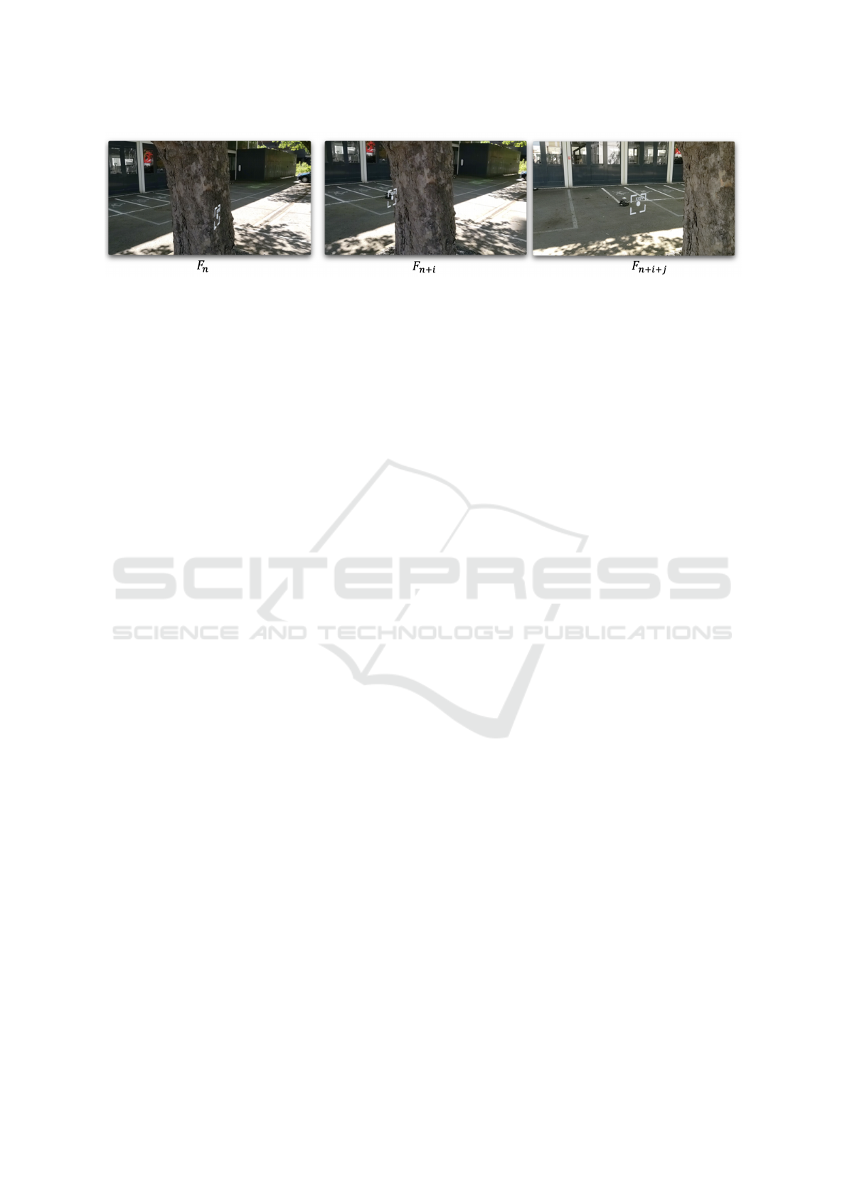
Figure 1: Tracking UGV using RTK systems. F
n
, F
n+i
and F
n+i+ j
are captured frames from Microsoft HoloLens v2. The
white virtual rectangle refers to the RTK information derived from RTK rover system located on UGV. A detailed demonstra-
tion of the experiment setup is available in the video: https://youtu.be/cqJEJmuMtsg.
sition relative to the world. Methods like match-
ing observed data to geotagged datasets (Zhang and
Kosecka, 2006) or using pre-built 2.5D models with
GPS alignment (Arth et al., 2015) offer solutions but
require substantial initial preparation. Similarly, deep
learning approaches, such as SSD-based object detec-
tion (Rao et al., 2017), combine rough GPS data with
sensor inputs for near real-time positioning. In this
paper, we propose using an RTK-equipped UGV to
establish a reference point, aligning the OST-HMD
coordinate frame with the world frame. This enables
accurate tracking of the UGV’s position on the OST-
HMD, as detailed in Section 3.5.
Accuracy Evaluation. The accuracy of a system
containing RTK or GPS can be evaluated in static or
dynamic scenarios. The RTK or GPS systems remain
fixed at a specific location (Wi
´
sniewski et al., 2013;
Safrel et al., 2018) in static conditions, while it keeps
changing its physical location in dynamic conditions
(Kluga et al., 2014; Tomaszewski et al., 2020). In this
paper, a semi-dynamic method is proposed, capturing
UGV positions at specific locations along a trajectory
(Tomaszewski et al., 2020). Unlike traditional static
or dynamic evaluations, this approach balances real-
world relevance with methodological rigor, providing
insights into system accuracy under varying condi-
tions. Details are provided in Section 4.
3 SYSTEM
3.1 Scenario
As highlighted in the introduction, the focus of this
work revolves around enhancing the management of
CBRN incidents through the visualization of tracked
a UGV. First responders, including firefighters, mili-
tary personnel, and other emergency teams, often face
critical situations where they must intervene to neu-
tralize, for example, a source of radiation in an urban
area. In these scenarios, the initial step involves de-
ploying a UGV equipped with a specialized gamma
camera (Gal et al., 2001). This camera is designed
to detect and pinpoint the exact location of the radi-
ation source, enabling the team to address the threat
effectively.
The key advantage of utilizing a UGV lies in its
ability to perform reconnaissance and intervention
tasks without putting human lives at risk. By keep-
ing first responders at a safe distance, the UGV mini-
mizes their exposure to dangerous levels of radiation
and other associated hazards. This approach not only
enhances the safety of emergency personnel but also
improves the efficiency and precision of the interven-
tion.
To further augment situational awareness and op-
erational effectiveness, we propose that first respon-
ders wear OST-HMD. These can overlay critical in-
formation directly into the responders’ field of vision,
including real-time data on the UGV’s position, radi-
ation levels, and other vital metrics. This integrated
system ensures that first responders have immediate
access to comprehensive information, facilitating in-
formed decision-making and coordinated actions dur-
ing the intervention.
Hence, we hypothesize that by combining the ca-
pabilities of UGV with OST-HMD, we can signifi-
cantly enhance the safety, accuracy, and efficiency of
radiation neutralization efforts in urban environments.
Consequently, in this investigation, we propose a sys-
tem to visualize tracked UGVs in outdoor environ-
ments via OST-HMD. This system addresses the ini-
tial research question RQ1: how can UGVs be effec-
tively visualized using OST-HMD when obstacles ob-
struct the view of object? To answer this question,
the system includes three main components, which
are detailed in the following Sections:
Real-Time Kinematic Positioning and Optical See-Through Head-Mounted Display for Outdoor Tracking: Hybrid System and Preliminary
Assessment
661
• The server application receives the positions of
the UGV and transmits this data to the OST-
HMD.
• Sensors in our scenario are UGVs equipped with
an RTK system. This system is composed of an
RTK rover and an RTK station. The position of
the RTK rover is corrected using the RTK sta-
tion, as will be illustrated later in Section 3.4. The
choice of the RTK system, as mentioned in the
introduction, offers significant advantages over
image-based tracking in scenarios involving ob-
stacles, adverse weather, or nighttime conditions.
• The AR application deployed on OST-HMD
serves as an interface for visualizing information
provided by the RTK rover.
3.2 Assess System Requirements
In CBRN management, free-hand operation for first
responders is essential. For this reason, OST-HMDs
were selected rather than handheld AR devices. A
Continuously Operating Reference Station (CORS)
network consists of a series of fixed reference stations
that continuously collect GNSS data. In such a sys-
tem, the rover corrects its position often via an inter-
net connection through a remote station provided by
the CORS network. Some countries around the world
provide CORS networks. In our case, the system was
not supported by CORS; hence a local station was
chosen. Furthermore, we opted for large-size RTK
systems to achieve the highest possible positional ac-
curacy. CBRN incidents often occur in urban areas,
so we evaluated the system in these areas (see Figure
2). Despite the fact that the RTK system provides less
accuracy and precision compared to open-sky condi-
tions.
3.3 Server Application
We utilized Tomcat, a web hosting service built
around the Java programming language. It offers a
REST API as well as socket connections. This server
is hosted on a web-based platform known as (Anony-
mous web server). The server receives the message
from sensors and broadcasts to the OST-HMD. Since
real-time communication is required, raw socket con-
nections are used. This offers lower latency compared
to HTTPS due to reduced protocol overhead and en-
cryption.
3.4 Sensors
Sensors such as UAVs, UGVs, or other types can be
used in CBRN management. In the scenario pre-
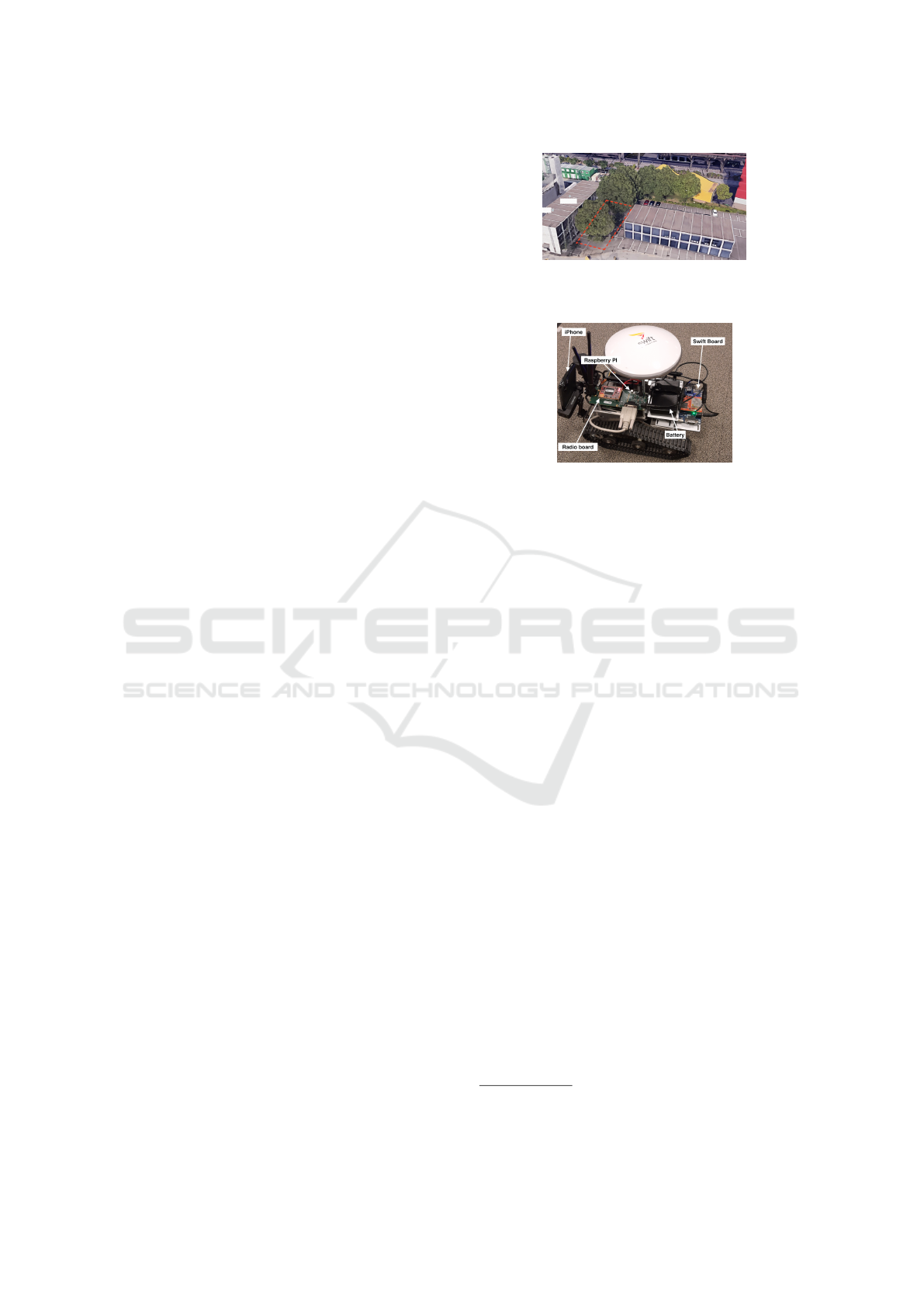
Figure 2: Picture captured from Google Earth. The area
highlighted in red is where the experimental test is con-
ducted.
Figure 3: UGV consists of an antenna, Swift Navigation
Piksi board, Radio board, battery, phone holder, iPhone 11
Pro, and Raspberry Pi, which is hidden by a radio board that
receives the correct position of the UGV using information
derived from the RTK station.
sented in Section 3.1, the sensor specifically refers
to one mounted on a UGV
1
. This latter operates
through a specialized application that communicates
via a dedicated WiFi network. This application serves
as the control interface, enabling users to remotely
manage and command the UGV’s movements. We
customized the UGV to fit our requirements, incorpo-
rating components such as an RTK rover (an antenna,
Swift Navigation Piksi board
2
, Radio board), phone
holder, iPhone 11 Pro and Raspberry Pi on the UGV
(see Figure 3). Moreover, an RTK station (see Figure
5) is used to transmit GNSS correction data over the
radio link to the RTK rover. The RTK station position
known as the ”surveyed position” is determined man-
ually or automatically. The surveyed position will be
used to correct the position derived from RTK rover.
In our case, the surveyed position was not available,
therefore, we used automatic surveyed position which
is generated using average of the last 1000 Single
Point Positioning (SPP) position solutions. Further-
more, RTK rover interfaces with the Raspberry Pi,
which facilitates the transmission of the UGV’s posi-
tion data to a web server known as (Anonymous web
server). Moreover, an iOS application is developed
and deployed on iPhone 11 Pro. The application pro-
vides GPS capabilities for location tracking and nav-
igation using the CLLocationManager class. This in-
formation is then sent to the web server, similar to the
information sent from the Raspberry Pi. Utilizing lo-
1
https://www.xiaorgeek.net
2
https://www.swiftnav.com
VISAPP 2025 - 20th International Conference on Computer Vision Theory and Applications
662

Figure 4: General schema of the proposed system.
cation information derived from the iPhone provides
us with the opportunity to compare it with RTK loca-
tion information, as illustrated in Section 4.
3.5 AR Application
In this investigation, HoloLens version 2 is used. An
AR application is developed using Unity3D. It’s con-
nected with UGV via the server application (see Fig-
ure 4). Moreover, we propose to utilize sun protection
filter
3
to reduce some of the effects of bright sun-
light on the outdoor experience. The HoloLens app is
based on vSLAM to generate a map of the surround-
ings and find its own location within it. Our main
contribution in this application is to respond to the
RQ2: how can data from RTK systems be seamlessly
integrated into OST-HMD? To answer this question,
the application contains two main functionalities: 1)
calibration to obtain a global location, and 2) location
update, as described below:
3.5.1 Calibration
Global location consists of finding the correct position
and orientation of the person wearing the HoloLens
relative to the world.
User’s Position. At the start, the person wear-
ing the HoloLens stands in the same location as the
UGV. This location is considered as the reference
point. Hence, the position P
world
re f
derived from the
RTK rover is the same as the position of the HoloLens
device P
HoloLens
re f
, but in different coordinate frames.
The first is in the World coordinate frame, and the
second is in the HoloLens coordinate frame. The two
positions P
World
re f
, P
HoloLens
re f
are saved to calculate the
updated positions.
User’s Orientation. The bearing angle indicates
the angle between the reference position P
World
re f
and
the UGV’s position P
World
relative to the north di-
rection. This angle is crucial for navigation and po-
sitioning tasks. If the OST-HMD coordinate frame
is aligned with the World coordinate frame, meaning
that the negative z-axis of the HoloLens aligns with
3
https://www.realsim.info/en-gb/
hololens-2-sonnenschutzfolie
the north direction, then the bearing angles calculated
in the World coordinate frame will match those in the
HoloLens coordinate frame. This alignment ensures
consistency in directional references across both sys-
tems. To achieve this alignment, at the beginning, the
user’s head direction, while wearing the OST-HMD,
should face the north direction. This initial orienta-
tion aligns the user’s perspective with the World coor-
dinate frame, facilitating accurate bearing angle mea-
surements and consistent spatial orientation.
3.5.2 Update Position
Keyhole Markup Language (KML) messages are
composed of the coordinates of the UGV in World
coordinate frame are transmitted to the server applica-
tion via the detected Wi-Fi network. The server relays
this data to the AR application, which then displays
the relevant information on OST-HMD. As mentioned
previously, sockets are employed to enable multiple
simultaneous messages between the various system
components. Therefore, to compute the position of
UGV in the HoloLens coordinate frame, we follow
these steps
• Computing the distance δ between UGV’s posi-
tion P
World
and reference position P
World
re f
which
refers to the previously saved reference position
from the calibration step
• Calculating the bearing angles between the ref-
erence position P
World
re f
and the UGV’s position
P
World
re f
in the World coordinate frame. This an-
gle will be the same in the HoloLens coordinate
frame thanks to the calibration step, which aligns
the negative z-axis of the HoloLens with the north
direction
Hence, the position P
HoloLens
v
of the virtual object cor-
responding to the position of UGV in HoloLens coor-
dinate frame is computed as follows:
P
HoloLens
v
= P
HoloLens
re f
+ P
HoloLens
δ
(1)
P
HoloLens
δ
=
δ · cos(β)
δ · sin(β)
0
(2)
Where P
hololens
δ
refers to the position after the ro-
tate of point (δ, 0, 0)
T
by the bearing angle β which
indicates the angle between the reference and UGV
positions according to north direction. Knowing that
the negative z axes of HoloLens coordinates system
is aligned with north direction via calibration steps
as mentioned previously. Hence, the AR application
transforms the RTK coordinates of UGV derived from
KML file into the HoloLens coordinate frame using
Real-Time Kinematic Positioning and Optical See-Through Head-Mounted Display for Outdoor Tracking: Hybrid System and Preliminary
Assessment
663
the reference position P
HoloLens
re f
. Therefore, the pro-
posed approach isn’t required to update the position
of the user wearing the HoloLens in each frame, as
in (Ling et al., 2019), thus avoiding noisy information
and providing more stable results.
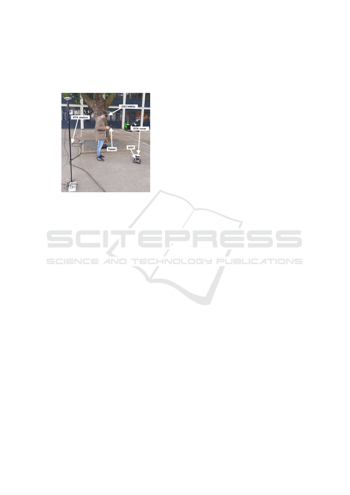
Figure 5: A prototype consisting of a UGV, RTK rover
(including an antenna, Swift Navigation Piksi board, and
Radio board), RTK station, tablet with a specific applica-
tion enabling users to remotely command the UGV’s move-
ments, and OST-HMD such as the HoloLens v2.
4 RESULTS
To accurately simulate a real-world scenario involv-
ing a CBRN incident in an urban environment, the
system as illustrated in Figure 5 was thoroughly eval-
uated in a mixed use urban area containing a diverse
array of structures such as multiple buildings, trees,
and various other environmental elements that would
typically surround the UGV. This complex and real-
istic urban landscape is illustrated in Figure 2. One
advantage of this system is that it can still track ob-
jects even when they’re not directly in sight, unlike
systems that rely on images. As illustrated in Fig-
ure 1, when the UGV is occluded by the tree, it can
still be tracked via the AR application. This can be
useful, especially in situations where you need to see
past obstacles. For example, in the context of a radi-
ological incident and the management of CBRN, the
utilization of OST-HMD by first responders could sig-
nificantly enhance their situational awareness. These
devices would enable them to gain a comprehensive
understanding of the scenario, facilitating real-time
observation of various elements, such as the location
of the UGV. Notably, the latter could be equipped
with systems similar to those integrated into our pro-
totype UGV, thereby extending the capabilities of the
response team to effectively assess and mitigate the
situation.
However, in this paper, we provide a prelimi-
nary evaluation of the system from the perspectives of
functionality and accuracy. Further study is required
to evaluate the system with end users, specifically first
responders.
The experimental test begins by locating the RTK
station and automatically determining its surveyed
position using more than 1,000 positions of the SPP
solution. This functionality is provided by the Swift
Navigation Piksi Multi RTK GNSS system. After-
ward, the UGV is positioned at a predetermined refer-
ence point. To calibrate the system, the person wear-
ing the OST-HMD stands as close as possible to the
UGV, holding a tablet to drive the UGV via a detected
WiFi network. Both the person and the UGV face the
north direction. Subsequently, the person wearing the
OST-HMD turns on the HoloLens and runs the appli-
cation. After the calibration step is complete, the per-
son starts driving the UGV via the tablet and is free to
move without any restrictions. A virtual object rep-
resenting the UGV follows the physical UGV, visual-
ized through the HoloLens. As mentioned in Section
2, in assessing GPS and RTK accuracy (see Figure 6),
two main methods are used: a) static: this involves
comparing specific GPS/RTK location data with the
real-world coordinates. It helps understand accuracy
in fixed positions. b) dynamic: unlike static, dynamic
analysis looks at the entire trajectory from GPS/RTK
against real-world movement. This helps assess accu-
racy while in motion, useful for tasks like navigation
and tracking. However, in our proposed methodology
for system evaluation, applying the dynamic method
has proven challenging. Synchronizing the movement
of both the UGV and the HoloLens wearer to capture
a full trajectory for error distance evaluation has pre-
sented difficulties. As a result, we propose a ”semi-
dynamic” approach, addressing RQ3: how well does
the semi-dynamic approach adapt to the challenges
of real-world UGV tracking evaluation compared to
static and dynamic methods? In this method, the
UGV is driven and paused at various locations to mea-
sure error distances before completing the route for a
more comprehensive evaluation.
To measure the error distance, our approach
(semi-dynamic) is grounded on the hypothesis that the
distance between the physical camera position of the
HoloLens and the virtual tracked object should ideally
be zero when the wearer of the HoloLens stands in the
same position as the UGV simultaneously precisely in
same position of RTK rover, disregarding any height
difference. We conducted multiple iterations of this
process, ensuring that error distances were recorded
while standing as close as possible to the RTK rover
antenna. Figure 7 illustrates the absolute error dis-
VISAPP 2025 - 20th International Conference on Computer Vision Theory and Applications
664
tances between the positions UGV measured using
RTK information and GPS information derived from
iPhone and the HoloLens camera position, knowing
that the y-axis of the HoloLens is set to zero, as our
aim is to calculate the error in a 2D plane without con-
sidering height.
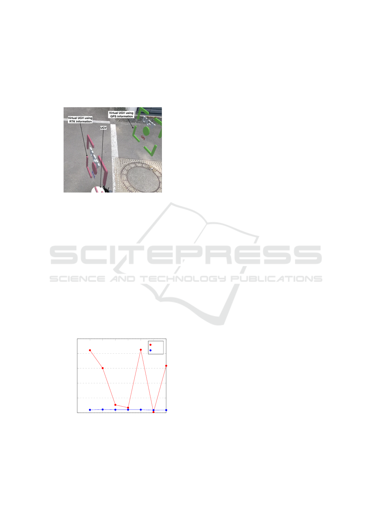
Figure 6: Tracking a UGV using RTK and GPS. Frame is
captured from HoloLens v2. The virtual objects (rose and
green rectangles) should be in the same position as the UGV
such that the green rectangle represents the GPS value de-
rived from the iPhone, and the rose rectangle represents the
RTK value derived from RTK rover.
As expected, we observe that the position of the
virtual object using GPS values is jumping and unsta-
ble in densely populated urban areas. In our experi-
ment, the standard deviation for the different positions
of a trajectory was approximately 7.453 meters. Con-
sequently, it’s necessary to apply a filter to these data
to reduce the jumping behavior. Conversely, RTK val-
ues exhibit a standard deviation of 0.126 meters and
provide more stable results. As shown in the Figure 7,
a shifted offset value between the real object and the
virtual one provided by RTK is approximately con-
stant observed. In line with expectations, RTK offers
greater precision than GPS, with an average of 0.745
1 2 3 4
5 6
7
0
4
8
12
16
20
Locations
Error (in m)
GPS
RTK
Figure 7: Scatter plot illustrating the errors in distance mea-
surements for several UGV locations obtained using both
RTK and GPS systems.
meters compared to 8.907 meters provided by GPS.
Although it is well known that RTK offers signif-
icantly higher accuracy than standard GPS, the pri-
mary objective of this experimental test is to demon-
strate that our methodology for the hybrid system of
OST-HMD and RTK—specifically the processes of
calibration and location updating—functions effec-
tively, while maintaining the high accuracy provided
by RTK.
5 LIMITATIONS AND FUTURE
DIRECTIONS
To optimize the OST-HMD and RTK system for out-
door tracking, key areas of improvement include:
Accuracy Enhancements. Leveraging RTK stations
with surveyed positions can simplify calibration and
improve accuracy. Adding sensors like a compass to
OST-HMDs could aid orientation calibration, while
improving depth sensors for outdoor conditions can
enhance vSLAM performance.
Network Latency. Reducing latency can be achieved
through multi-threading, network optimization, and
using UDP for faster communication. Predictive ren-
dering on OST-HMDs can also compensate for delays
by anticipating object movements.
Visualization. Challenges in aligning virtual objects
with real-world counterparts in outdoor environments
remain. Research is needed on optimal virtual ob-
ject shapes, perception changes with distance, main-
taining alignment across terrains, and the impact of
lighting and weather. Using sun filters and adapt-
ing to outdoor lighting conditions can enhance visibil-
ity, while exploring sensory augmentations like sound
could improve usability. Addressing these challenges
could significantly improve OST-HMD and RTK in-
tegration for real-world applications.
6 CONCLUSION
Current OST-HMDs overcome many limitations of
VST-HMDs but still face challenges when used in
outdoor environments. This paper proposes an ap-
proach to integrate data from an RTK system and
track this information using the vSLAM algorithm
in OST-HMD. We hypothesize that combining UGV,
OST-HMD, and accurate positioning can enhance the
ability of first responders to manage incidents, par-
ticularly by improving their capability to visualize
occluded information, thereby increasing situational
awareness and safety.
Real-Time Kinematic Positioning and Optical See-Through Head-Mounted Display for Outdoor Tracking: Hybrid System and Preliminary
Assessment
665

Our system consists of three core components: (1)
a web server that receives data from a UGV and trans-
mits it to OST-HMD via a socket connection; (2) a
UGV equipped with an RTK rover system; and (3) the
HoloLens 2, serving as the OST-HMD. A detailed cal-
ibration step, which ensures accurate global tracking
of the user’s position and orientation, is illustrated.
In this paper, we present a preliminary evalua-
tion of the system in terms of functionality and accu-
racy. Further research is necessary to assess the sys-
tem with end users, specifically first responders. In
conclusion, this paper advances the state of the art in
outdoor RTK positioning with OST-HMD, proposing
a comprehensive system for visualizing UGV data via
OST-HMD while also highlighting areas for future re-
search.
ACKNOWLEDGEMENTS
Muhannad Ismael and Ma
¨
el Cornil are supported by
the Luxembourg Institute of Science and Technology
(LIST) and the Luxembourg National Research Fund
(FNR) under the RISARX project (Grant Number
15340411). We express our gratitude to Dr. Roderick
McCall for his support and insightful discussions, Mr.
Christian Moll and Mr. Johannes Hermen for their as-
sistance in constructing the UGV, and Dr. Mohamed
Saifeddine Hadj Sassi for his logistical coordination
during the outdoor evaluation.
REFERENCES
Arth, C., Pirchheim, C., Ventura, J., Schmalstieg, D.,
and Lepetit, V. (2015). Instant outdoor localiza-
tion and slam initialization from 2.5 d maps. IEEE
Transactions on Visualization & Computer Graphics,
21(11):1309–1318.
Benjumea, A., Teeti, I., Cuzzolin, F., and Bradley, A.
(2021). YOLO-Z: improving small object detec-
tion in yolov5 for autonomous vehicles. CoRR,
abs/2112.11798.
De Pace, F. and Kaufmann, H. (2023). A systematic eval-
uation of an rtk-gps device for wearable augmented
reality. Virtual Reality, 27(4):3165–3179.
Gal, O., Izac, C., Jean, F., Lain
´
e, F., L
´
ev
ˆ
eque, C., and
Nguyen, A. (2001). Cartogam–a portable gamma
camera for remote localisation of radioactive sources
in nuclear facilities. Nuclear Instruments and Meth-
ods in Physics Research Section A: Accelerators,
Spectrometers, Detectors and Associated Equipment,
460(1):138–145.
Gan-Mor, S., Clark, R. L., and Upchurch, B. L. (2007). Im-
plement lateral position accuracy under rtk-gps tractor
guidance. Computers and Electronics in Agriculture,
59(1-2):31–38.
Kluga, A., Mitrofanovs, I., Kluga, J., and Jeralovics, V.
(2014). State and dynamic precision research using
two gps receivers with rtk. In 2014 14th Biennial
Baltic Electronic Conference (BEC), pages 141–144.
IEEE.
Ling, F. F., Elvezio, C., Bullock, J., Henderson, S., and
Feiner, S. (2019). A hybrid rtk gnss and slam outdoor
augmented reality system. In 2019 IEEE Conference
on Virtual Reality and 3D User Interfaces (VR), pages
1044–1045.
Oskiper, T., Samarasekera, S., and Kumar, R. (2012). Multi-
sensor navigation algorithm using monocular camera,
imu and gps for large scale augmented reality. In
2012 IEEE international symposium on mixed and
augmented reality (ISMAR), pages 71–80. IEEE.
Rao, J., Qiao, Y., Ren, F., Wang, J., and Du, Q. (2017).
A mobile outdoor augmented reality method combin-
ing deep learning object detection and spatial relation-
ships for geovisualization. Sensors, 17(9):1951.
Roberts, G. W., Evans, A., Dodson, A., Denby, B., Cooper,
S., Hollands, R., et al. (2002). The use of augmented
reality, gps and ins for subsurface data visualization.
In FIG XXII international congress, volume 4, pages
1–12.
Safrel, I., Julianto, E. N., and Usman, N. Q. (2018). Ac-
curacy comparison between gps real time kinematic
(rtk) method and total station to determine the coordi-
nate of an area. Jurnal Teknik Sipil Dan Perencanaan,
20(2):123–130.
Satheesan, A. (2024). Real-time augmented reality based
operator assistance for driving cut-to-length forest
machines.
Schall, G., Wagner, D., Reitmayr, G., Taichmann,
E., Wieser, M., Schmalstieg, D., and Hofmann-
Wellenhof, B. (2009). Global pose estimation using
multi-sensor fusion for outdoor augmented reality. In
2009 8th ieee international symposium on mixed and
augmented reality, pages 153–162. IEEE.
Stranner, M., Arth, C., Schmalstieg, D., and Fleck, P.
(2019). A high-precision localization device for out-
door augmented reality. In 2019 IEEE International
Symposium on Mixed and Augmented Reality Adjunct
(ISMAR-Adjunct), pages 37–41. IEEE.
Tomaszewski, D., Wielgosz, P., Rapi
´
nski, J., Krypiak-
Gregorczyk, A., Ka
´
zmierczak, R., Hern
´
andez-Pajares,
M., Yang, H., and Or
´
usP
´
erez, R. (2020). Assessment
of centre national d’
`
etudes spatiales real-time iono-
sphere maps in instantaneous precise real-time kine-
matic positioning over medium and long baselines.
Sensors, 20(8):2293.
Wi
´
sniewski, B., Bruniecki, K., and Moszy
´
nski, M. (2013).
Evaluation of rtklib’s positioning accuracy usingn
low-cost gnss receiver and asg-eupos. TransNav: In-
ternational Journal on Marine Navigation and Safety
of Sea Transportation, 7(1):79–85.
Zhang, W. and Kosecka, J. (2006). Image based localization
in urban environments. In Third international sympo-
sium on 3D data processing, visualization, and trans-
mission (3DPVT’06), pages 33–40. IEEE.
VISAPP 2025 - 20th International Conference on Computer Vision Theory and Applications
666
