
Heat Transfer in Laparoscopic Trocar System: Analytical and
Numerical Study
Mohammad Al Amin Al Tahhan
1
, Wassim Salameh
2
, Ali Shaito
1
, Ali Cherry
3
, Soumaya Berro
4
and Mohamad Hajj-Hassan
4
1
Department of Mechanical Engineering, Lebanese International University, Bekaa, Lebanon
2
Department of Mechanical Engineering, The International University of Beirut, Beirut, Lebanon
3
Department of Biomedical Engineering, The International University of Beirut, Beirut, Lebanon
4
Department of Biomedical Engineering, Lebanese International University, Bekaa, Lebanon
Keywords: Laparoscopy, Trocar, Fluid Flow, Heat Transfer.
Abstract: In laparoscopic surgeries, CO
2
insufflation through a trocar system is required to fill the abdominal or pelvic
cavity and provide a working space for the surgeon. The problem arises from the heat loss from the CO
2
gas
to the surroundings of the trocar since it results in a temperature difference between the entering CO
2
and the
temperature of the patient’s body, which results in fog formation on the camera lens, blocking the surgeon’s
vision. This heat loss occurs by convection between the flowing fluid inside and outside the trocar and by
conduction through the trocar’s cannula. The primary objective of this research is to investigate the heat loss
of CO
2
through the trocar cannula for different materials. These materials should meet specific requirements
in order to be used in such surgery. The requirements are biocompatibility, transparency, eco-friendliness,
and solid state. The selected materials are PET, PVDF, PEI, PEEK, and PC. Heat transfer and finite element
analysis case studies were investigated to observe internal fluid flow behavior for velocity profile and
temperature distribution. Then, a model was created and simulated on ANSYS workbench using proper
boundary conditions that match real-life conditions. Comparative studies were done using ANSYS for the
velocity profile, mean temperature distribution, axial temperature distribution, and radial temperature
distribution of CO
2
. The simulated results showed that PVDF was the best material to be used in the
composition of the trocar’s cannula since it resisted the most heat transfer, followed by PC, PET, PEEK, and
PEI, respectively.
1 INTRODUCTION
Laparoscopic surgery, known as keyhole surgery, is
an exploratory surgery that allows the surgeon to
explore and examine the abdominal and/or pelvic
cavities through a simple mechanism performed by
creating a small incision near the belly button or
pelvic bone and inserting a narrow surgical tube
called a trocar through this incision. A trocar is a
specialized medical equipment that acts as a port for
different uses, such as the insertion of surgical
instruments and carbon dioxide (CO
2
) insufflation.
The carbon dioxide insufflation is done by inserting a
gas tube into the trocar to fill the patient’s abdominal
or pelvic cavity with CO
2
gas in order to separate the
abdominal wall from other organs for clearance and
more visibility of the examined area on the video
monitor (Cleveland, 2024).
During CO
2
insufflation operation, heat loss
occurs from the CO
2
passing through the trocar into
the patient’s body by conduction and convection due
to the temperature difference between the CO
2
flowing in the trocar, which has the same temperature
as the abdominal cavity initially, and the operation
room’s low temperature. This heat loss creates a
difference in temperature between the CO
2
entering
the body and the body’s temperature, which leads to
condensation on the camera lens that separates them.
The condensation will result in water vapor formation
on the camera lens, which will fog the surgeon’s view
during the surgery.
Here, the trocar is modeled as a pipe with an
internal fluid flow. This assumption was made for
comparison with a numerical and experimental heat
transfer study conducted on an internal laminar fluid
flow to observe the velocity magnitude with respect
132
Al Tahhan, M. A., Salameh, W., Shaito, A., Cherry, A., Berro, S. and Hajj-Hassan, M.
Heat Transfer in Laparoscopic Trocar System: Analytical and Numerical Study.
DOI: 10.5220/0013132900003911
Paper published under CC license (CC BY-NC-ND 4.0)
In Proceedings of the 18th International Joint Conference on Biomedical Engineer ing Systems and Technologies (BIOSTEC 2025) - Volume 1, pages 132-138
ISBN: 978-989-758-731-3; ISSN: 2184-4305
Proceedings Copyright © 2025 by SCITEPRESS – Science and Technology Publications, Lda.
to the tube diameter (Al‐Obaidi, 2021). It was
observed that the velocity profile resulted in a
parabolic shape. A study was done on a pipe with
internal turbulent water flow exposed to a constant
wall temperature of 500 K, 750 K, and 1000 K (Al-
Zaharnah, 2004). It was observed that the
dimensionless temperature increases when the
studied point is farther away from the center, closer
to the inner radius, and toward the end of the pipe.
This increase in the dimensionless temperature means
that the fluid’s temperature is increasing. Another
study on ANSYS and MATLAB shed light on the
heat loss in a pipeline with multiple insulation layers
with an internal turbulent fluid flow (Patil, 2016). The
pipe layers consisted of glass wool, aluminium foil,
and steel with different thicknesses. It was observed
that the initial temperature of the steam flowing inside
the pipe, at 0 m in length, was 503 K. Then, it
decreased gradually throughout the pipe’s length to
reach a temperature of 423 K. A study on a vertical
hollow cylinder having specific dimensions was done
on ANSYS (Chandrakar, 2021). The cylinder having
an internal fluid flow and exposed to high and low
temperatures was studied. At lower temperatures, 350
K and 400 K, the convection and radiation heat
transfer rates increased similarly. At higher
temperatures, 450 K to 550 K, the increase in heat
transfer rate by radiation was higher than that by
convection. A heat transfer study using the
orthogonal collocation method was done on a circular
tube with laminar and fully developed internal fluid
flow, exposed to a constant wall temperature
(Belhocine, 2016). The dimensionless temperature
decreases exponentially when the fluid moves
towards the end of the tube, which means that the
temperature of the fluid is getting higher and is thus
getting closer to the high wall temperature.
The material of the trocar’s cannula must be
precisely selected to meet the proper material
requirements which are: biocompatibility,
transparency, eco-friendliness, and solid state. The
material should also be able to have minimal heat
transfer; it should act as an insulation material.
Multiple materials will be selected while adhering to
these requirements in order to reduce heat loss in the
trocar's cannula during the CO
2
insufflation
operation, which will reduce the condensation
occurring on the camera lens. A simulation on
ANSYS workbench will be conducted to compare the
heat loss through the trocar using different materials
in the cannula composition under real-life conditions.
The trocar is modeled as a tube with an inner and
outer diameter. The CO
2
fluid will flow through the
inner diameter, and the tube will be exposed to
ambient air flow with a low temperature at the outer
diameter. The outcome of the numerical study will
determine the temperature distribution that will be
observed along the trocar.
An ANSYS simulation for the velocity profile
will take place, and then it will be validated using
theoretical equations and a previous published case
study. After that, the mean, axial, and radial
temperature distributions will be simulated in order to
find the best trocar material to resist heat transfer.
2 METHODOLOGY
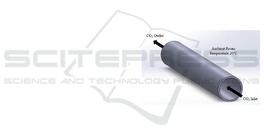
The trocar is modeled based on the characteristics of
the commercial trocar system from XNY Medical, a
manufacturer and distributor of minimal invasive
surgery (MIS) medical devices, China. The trocar is
considered to be a hollow tube with an internal CO
2
fluid flow and a surrounding ambient operating room
temperature of 20
o
C causing natural convection, as
shown in Figure 1.
Figure 1: Trocar Model.
2.1 Material Selection
In the medical field, it is important to abide by the
specific material requirements, which are, in this
case, biocompatibility, transparency, eco-
friendliness, and solid state. By definition,
biocompatible materials are polymers, metals, and
ceramics that don’t produce an immune or toxic
response within the human body. It is vital for the
trocar to use a biocompatible material since it protects
the patient from adverse reactions such as infection,
toxicity, or an allergic response when it’s inserted into
the body. Another material requirement to take into
consideration is the trocar’s optical transparency,
since it helps the surgeon visualize the tissue layers
before the trocar’s insertion in order to prevent organ
injury (Tanaka, 2019). Finally, it’s important for
Heat Transfer in Laparoscopic Trocar System: Analytical and Numerical Study
133
trocars to have a solid state and to be composed of
eco-friendly material.
The common trocar’s materials that meet these
requirements are PolyEthylene Terephthalate (PET),
PolyVinyliDene Fluoride (PVDF), PolyCarbonate
(PC), Poly-EtherImide (PEI), and Polyether Ether
Ketone (PEEK).
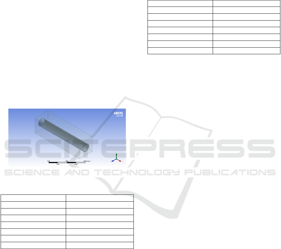
2.2 Numerical Model
The trocar is modeled as a hollow tube, as shown in
Figure 2, that has the geometry shown in Table 1. This
tube has a solid state and its properties were set
according to the materials tested. The CO
2
fluid
passing through the trocar was modeled as a cylinder.
This cylinder has a fluid state to represent the CO
2
and the suitable properties of CO
2
were inserted.
When it comes to the ambient air surrounding the
trocar, a rectangular box was modeled as fluid to
represent the air flowing in the room, causing natural
convection.
Figure 2: Trocar Model in ANSYS.
Table 1: Dimensions of the model components.
Parameter Value
Tube Length 103 mm
Inlet Diamete
r
13 mm
Outlet Diamete
r
15 mm
Tube Thickness 1 mm
Box Length 30 mm
Box Width 103 mm
Box Height 30 mm
In the trocar model simulation, the boundary
conditions are set to match the operating room
conditions, where the CO
2
insufflation operation
takes place. The CO
2
entering the trocar has an initial
temperature and a volumetric flow rate which are
shown in Table 2. On the other hand, the ambient air
surrounding the trocar has a temperature and a
velocity magnitude, which create a constant heat flux
on the surface of the trocar. A box was created to
represent the ambient air surrounding the trocar. The
constant heat transfer coefficient of the CO
2
is
calculated and set on the surface of the inner diameter
of the trocar. In addition, the heat transfer coefficient
of air is assumed, according to the range of typical
values of free convection gases, and set on the surface
of the outer diameter of the tube (Incropera, 1996).
Table 2: Simulation conditions.
Parameter Value
Tube Length 103 mm
Inlet Diamete
r
13 mm
Outlet Diamete
r
15 mm
Tube Thickness 1 mm
Box Len
g
th 30 mm
Box Width 103 mm
Box Height 30 mm
2.3 Velocity Profile
The internal volumetric flow rate of CO
2
in this study
during the CO
2
insufflation operation is assumed to
be in the range of 0.1 to 3 L/min. First, the mesh
sensitivity will be studied. Second, the velocity
profile will be simulated on ANSYS, and then the
theoretical equations will be gathered. After that, a
comparative study will take place between the results
of the simulation, theoretical, and a previous case
study in order to validate the ANSYS model.
2.3.1 Model Mesh Sensitivity
Meshing has an important role in modeling and
simulation since it is a method of breaking down the
model into elements by generating grids. Meshing is
used to discretize and analyze the simulation. The
mesh types that are used in the ANSYS simulation are
the linear, quadratic, program-controlled, tetrahedral,
and hexa core types. A comparative study of the
velocity profile between the theoretical and the
simulation at 0.5 L/min internal flow using different
types of mesh at 1 mm mesh size will indicate the
most accurate mesh type. Figure 3 represents the
variation of speed with respect to the radial position.
The velocity profile for the internal CO
2
fluid flow
is shown to have a parabolic shape. It was observed
from the results above that the quadratic and the
program-controlled mesh types had the closest peak
speeds and parabolic shapes to the theoretical results,
which makes them the most accurate types of mesh.
The mesh element size indicates the accuracy of
the results and the number of meshes required for the
model to be divided into, which means that a smaller
element size will give more accurate results (Dutt,
2015). A comparative study of the velocity profile
between the theoretical and the simulation at 0.5
L/min internal flow using quadratic mesh having
BIODEVICES 2025 - 18th International Conference on Biomedical Electronics and Devices
134
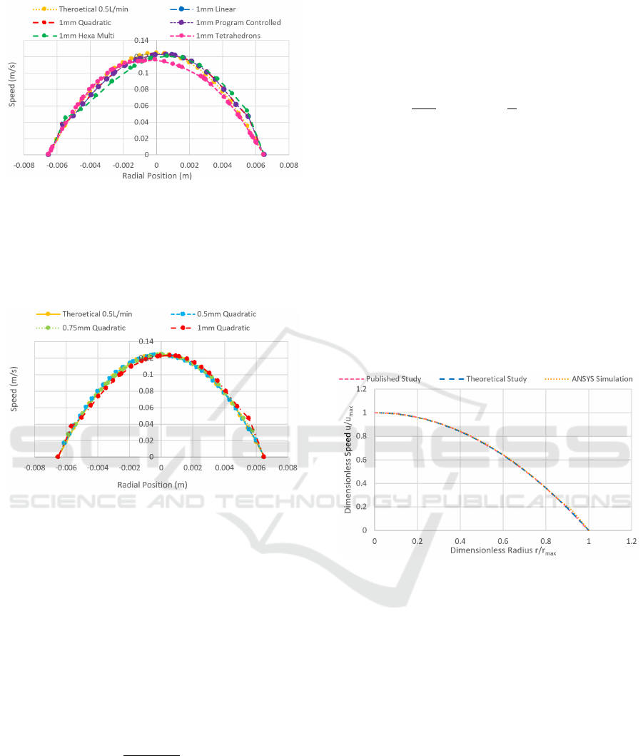
Figure 3: Variation of the speed for different mesh types
with respect to the radial position.
different element sizes of 0.5, 0.75, and 1 mm, will
indicate the most accurate element size. Figure 4
represents the variation of speed with respect to the
radial position.
Figure 4: Variation of the speed for different mesh element
sizes with respect to the radial position.
According to the results above, the 0.5 mm
element size was the most accurate since it was the
closest to the theoretical peak speed and the nearest
to the theoretical parabolic shape. Therefore, the 0.5
mm quadratic mesh will be used for further
simulations since it has the highest mesh sensitivity.
2.3.2 Analytical Model
To indicate the type of internal flow, Reynolds
number will be studied at different volumetric flow
rates. The Reynolds number is expressed as:
𝑅𝑒 =
𝜌×𝑢×𝑑
𝜇
(1)
Where Re is Reynolds number (unitless), ρ is the
fluid's density (kg/m
3
), u is the fluid's speed with
respect to the cylinder (m/s), d
i
is the cylinder's inner
diameter (m), and μ is the fluid's dynamic viscosity
(kg/m.s) (Incropera, 1996).
Using Equation 1, Reynolds number has a range
of 18.879 to 566.38 over the volumetric flow rate
range, which means that the internal CO
2
fluid flow
is laminar since Reynolds number is less than 2300
(Incropera, 1996).
The equation of the dimensionless velocity profile
of a laminar flow in a cylinder is represented by:
𝑢(𝑟)
𝑢
=2×1−(
𝑟
𝑟
)
(2)
Where u
m
is the mean speed of the fluid (m/s), r is
the radius of the studied location (m), and r
i
is the
inner radius of the cylinder (m).
To validate the ANSYS model, a comparative
study will take place between the simulated results,
theoretical results, and a previous published case
study for the velocity profile. A previous published
paper studied internal water flow in a pipe having a
0.5 m inner radius, a 1 m pipe length, and a maximum
speed of 0.7 m/s (Najmi, 2017). After plotting the
dimensionless speed with respect to the
dimensionless radius for each one, as shown in Figure
5, it was observed that they had similar curves, which
validates the ANSYS model.
Figure 5: Dimensionless speed with respect to
dimensionless radius for different studies.
2.4 Heat Transfer
During CO
2
insufflation operation, heat transfer in the
trocar takes place by convection (both externally and
internally) and conduction. The external convention
occurs between the trocar surface and the air inside
the room, while the internal convection occurs
between the moving CO
2
gas inside the trocar and its
walls. The conduction occurs through the thickness of
the trocar’s cannula. To compare the materials used
in the trocar’s composition, a thermal comparative
study will be done on ANSYS using different trocar
materials. The boundary conditions were properly set
in ANSYS Fluent, as previously stated. The material
of the tube was assigned separately to be PET, PVDF,
PC, PEI, and PEEK, along with their properties. The
mean, axial, and radial CO
2
temperature distributions
Heat Transfer in Laparoscopic Trocar System: Analytical and Numerical Study
135
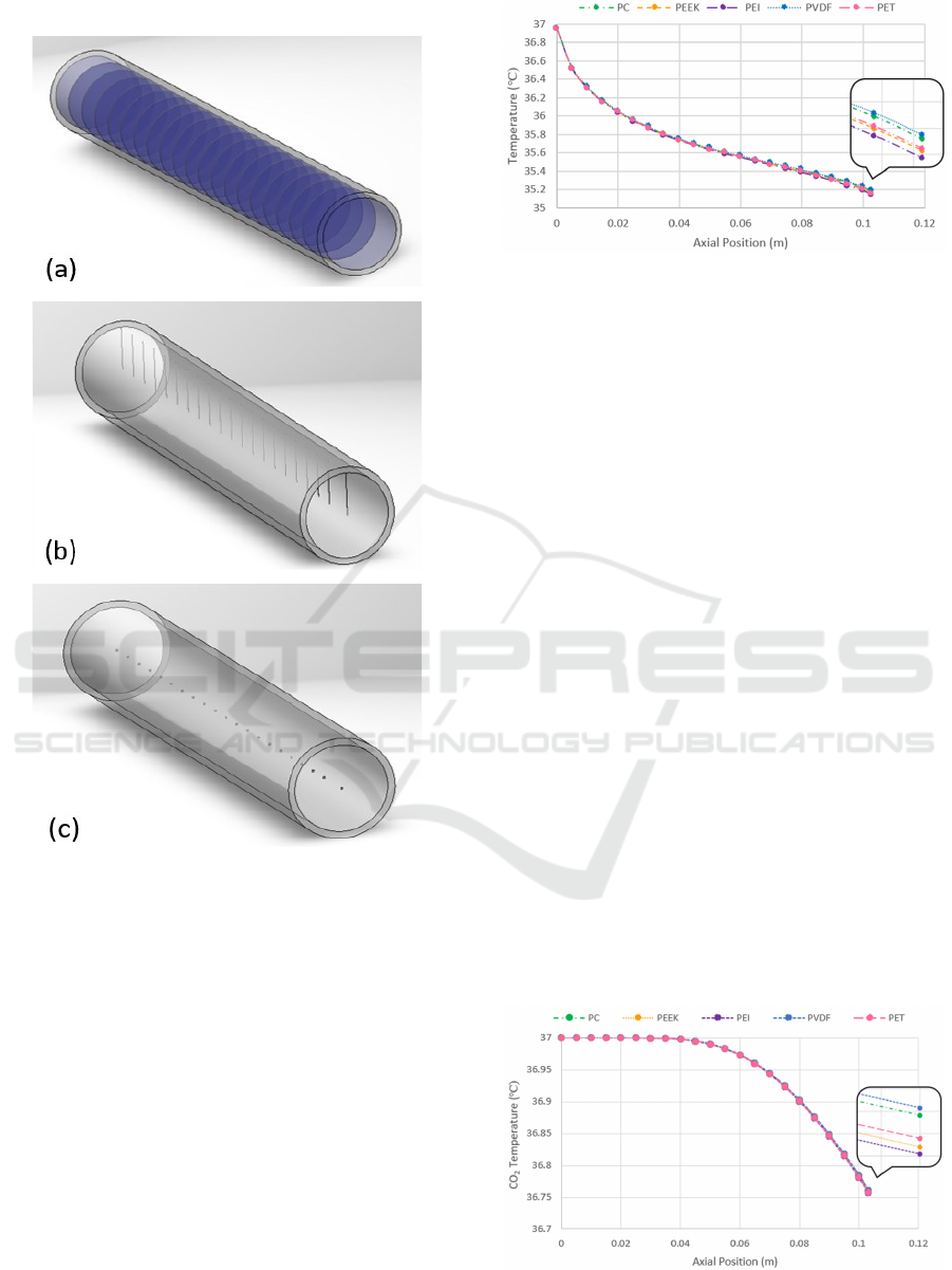
were simulated on ANSYS as shown in Figure 6.
Figure 6: (a) Mean Temperature Distribution Simulation,
(b) Axial Temperature Distribution Simulation, (c) Radial
Temperature Distribution Simulation.
3 RESULTS
3.1 Mean Temperature Distribution
After simulating the ANSYS model, the results of the
mean temperature were obtained along the axial
position with an increment of 5 mm, as shown in
Figure 7.
To analyze Figure 7, all the mean temperature
curves using different materials started at 37 ℃ at the
inlet of the tube. Then, they reached different values
at the end of the tube, at 0.103 m, using different
materials. It was observed from the results that the
material that most resisted heat transfer was PVDF,
Figure 7: The mean temperature distribution of CO
2
at the
axial position using different materials.
which has the lowest thermal conductivity of 0.185
W/m.K. PVDF showed the highest CO
2
mean
temperature of 35.188 ℃, which is the closest to the
CO
2
initial inlet temperature, 37 ℃. PC showed a
lower mean temperature of CO
2
than PVDF followed
by PET and PEEK, respectively. Finally, the least
material that resisted heat transfer was PEI, which has
the highest thermal conductivity of 0.328 W/m.K.
PEI had the lowest mean temperature of 35.143 ℃,
which is the farthest away from the CO
2
initial inlet
temperature.
3.2 Axial Temperature Distribution
After simulating the ANSYS model, the results of the
axial temperature were obtained along the axial
position, as shown in Figure 8. The temperature of the
internal CO
2
fluid started at 37 ℃ and then started to
decrease along the trocar’s length to reach different
values at the end of the trocar using different trocar
materials. It was observed that the trocar material that
resisted CO
2
heat loss the most along the length of the
trocar was PVDF. This is because it has the lowest
thermal conductivity of 0.185 W/m.K and the CO
2
temperature decreased the least from 37 ℃ at the
beginning of the trocar to 36.76132 ℃ at the end of
the trocar. PC resulted in a lower axial temperature of
Figure 8: Distribution of CO
2
along the axial position using
different materials.
BIODEVICES 2025 - 18th International Conference on Biomedical Electronics and Devices
136
CO
2
followed by PET and PEEK, respectively.
Finally, the least material that resisted heat transfer
was PEI, which has the highest thermal conductivity
of 0.328 W/m.K and resulted in the lowest axial
temperature, which is the farthest from the CO
2
initial
inlet temperature.
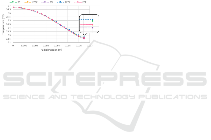
3.3 Radial Temperature Distribution
After simulating the ANSYS model, the results of the
radial temperature were obtained along the radial
position, as shown in Figure 9.
Figure 9: Temperature distribution of CO
2
with respect to
the radial position using different trocar materials.
Figure 9 shows the temperature distribution of
CO
2
along the radial position. For all materials, the
curves start at a specific peak value at the center of
the trocar and then decrease as they get closer to the
inner wall of the trocar. It was observed that the CO
2
temperature at the inner wall of the trocar was the
highest, with a value of 32.699 ℃, when the trocar
material was PVDF. The temperature difference was
the lowest, 3.569 ℃, which means that PVDF
exhibited the highest resistance to heat transfer.
Following that is PC, which showed a lower CO
2
temperature at the inner wall of the trocar and a
greater temperature difference; next is PET, followed
by PEEK. The material that resisted heat transfer the
least was PEI, which had the lowest CO
2
temperature
at the inner wall, with a value of 32.524 ℃, and the
highest temperature difference of 3.734 ℃.
4 CONCLUSIONS
In laparoscopic surgeries, during CO
2
insufflation, the
CO
2
entering a patient’s body at 37 ℃ through the
trocar loses heat due to its surroundings. This
temperature difference causes fog to form on the
camera lens inside the body. In order to mitigate this
heat transfer, multiple materials that can be used in the
composition of the trocar were compared to determine
which material results in the least temperature
difference between the inlet and outlet of the trocar,
thereby reducing condensation. The selected materials
are PET, PVDF, PEI, PEEK, and PC.
The trocar was modeled using ANSYS Fluent
Fluid Flow, where proper boundary conditions and
geometry were applied to match the trocar and the
operating room conditions. The ANSYS simulation
was validated by a comparative study with the
theoretical equation and a previous case study.
The mean, axial, and radial temperature
distributions using each of the five materials in the
composition of the trocar were plotted using ANSYS.
Results showed that PVDF, having the lowest
thermal conductivity, had the highest resistance to
heat transfer with a CO
2
mean temperature of
35.18817 ℃ and an axial temperature of 36.76132 ℃
at the end of the trocar’s length. It was followed by
PC, PET, PEEK, and PEI. Moreover, the CO
2
radial
temperature distribution indicated that PVDF also
had the highest resistance to heat loss radially with a
CO
2
temperature difference of 3.569 ℃ from the
center to the trocar inner surface at the end of the
trocar, followed by PC, PET, PEEK, and PEI.
In summary, the best material that can be used in
the composition of the trocar is PVDF since it has the
greatest CO
2
heat loss resistance throughout the
length of the trocar, which will result in the least fog
formation on the camera lens.
As a future plan, an experimental study will be
performed using different trocar materials in order to
study the actual CO
2
temperature distribution along
the trocar. Validating the numerical and
computational methods using an experimental study
will lead to refining the model and confirming the
optimal material to be used in the trocar composition,
which will result in minimal CO
2
heat loss to prevent
fog formation.
REFERENCES
Treatments. Cleveland Clinic. (n.d.). https://my.
clevelandclinic.org/health/treatments, (accessed
2024/7/21).
Al‐Obaidi, A. R. (2021). Investigation of the flow, pressure
drop characteristics, and augmentation of heat
performance in a 3D flow pipe based on different
inserts of twisted tape configurations. Heat Transfer,
50(5), 5049–5079. https://doi.org/10.1002/htj.22115.
Al-Zaharnah, I., & Yilbas, B. (2004). Thermal analysis in
pipe flow: Influence of variable viscosity on entropy
generation. Entropy, 6(3), 344–363. https://doi.
org/10.3390/e6030344.
Heat Transfer in Laparoscopic Trocar System: Analytical and Numerical Study
137

Patil, M. M., Nadar, M. D., & Uthale, S. A. (2016). To
investigate Heat Loss of a Fluid flowing through a
Pipeline for Turbulent Flow. International Journal of
Advanced Engineering Research and Applications
(IJAERA).
Chandrakar, V., Senapati, J. R., & Mohanty, A. (2021).
Conjugate heat transfer due to conduction, natural
convection, and radiation from a vertical hollow
cylinder with finite thickness. Numerical Heat Transfer,
Part A: Applications, 79(6), 463-487.
Belhocine, A. (2016). Numerical study of heat transfer in
fully developed laminar flow inside a circular tube. The
International Journal of Advanced Manufacturing
Technology, 85, 2681-2692.
Tanaka, C., Fujiwara, M., Kanda, M., Murotani, K., Iwata,
N., Hayashi, M., ... & Kodera, Y. (2019). Optical trocar
access for initial trocar placement in laparoscopic
gastrointestinal surgery: A propensity score‐matching
analysis. Asian Journal of Endoscopic Surgery, 12(1),
37-42.
Incropera, F. P., DeWitt, D. P., Bergman, T. L., & Lavine,
A. S. (1996). Fundamentals of heat and mass transfer
(Vol. 6, p. 116). New York: Wiley.
Dutt, A. (2015). Effect of mesh size on finite element
analysis of beam. International Journal of Mechanical
Engineering, 2(12), 8-10.
Najmi, J., & Ali Shah, S. I. (2017). Analysis of Velocity
Profile for Laminar Flow in a Round Pipe. Fifth
International Conference on Aerospace Science &
Engineering (ICASE), Institute of Space Technology,
Islamabad, Pakistan (2017).
BIODEVICES 2025 - 18th International Conference on Biomedical Electronics and Devices
138
