
Galerkin Enhanced Graph-Based FEM for Interactive Fracture and
Sculpting Applications
Avirup Mandal
1,∗ a
, Parag Chaudhuri
2 b
and Subhasis Chaudhuri
3 c
1
Department of Computer Science and Engineering, Indian Institute of Technology Palakkad, Kanjikode, India
2
Department of Computer Science and Engineering, Indian Institute of Technology Bombay, Mumbai, India
3
Department of Electrical Engineering, Indian Institute of Technology Bombay, Mumbai, India
Keywords:
Interactive Fracture, Graph-Based FEM, Galerkin Multigrid, Sculpting.
Abstract:
Physically-based fracture and cutting simulations are rarely incorporated in interactive graphics systems be-
cause the required computation stifles the speed of interaction. We enhance a physically based method for
object deformation and fracture by using multigrid approximations to expedite the full dynamics solve of the
system. Our method combines a Galerkin multigrid approach with the graph-based Finite Element Method so
that remeshing-free fracture and cutting simulation can be done by solving the system dynamics on a hierarchy
of coarse to fine meshes while accumulating residual error that is fully resolved only at the coarsest level. We
demonstrate the effectiveness of our algorithm by using it to develop an interactive virtual sculpting framework
that enables users to shape object meshes in a physically consistent manner. We compare our method with
other state-of-the-art virtual 3D object editing solutions to show that our method can provide better physically
consistent solutions at interactive speeds.
1 INTRODUCTION
Fracture simulation is crucial in various graph-
ics applications for immersive virtual content cre-
ation. Applications such as video games, mixed re-
ality experiences, and surgical simulators require vi-
sually appealing fracture simulations and instanta-
neous interaction feedback. To achieve high frame
rates with physical plausibility, stable large-time-
step simulations for fracture simulations, the Fi-
nite Element Method (FEM) (O’Brien and Hodgins,
1999) (Pfaff et al., 2014) (Chitalu et al., 2020),
Boundary Element Method (BEM) (Hahn and Woj-
tan, 2015) (Hahn and Wojtan, 2016). Material Point
Method (MPM) (Wolper et al., 2019) (Wolper et al.,
2020) are widely used. These methods utilize an
implicit time integration scheme; however, they are
computationally expensive, and the computational
cost increases with the number of cracks in the object
a
https://orcid.org/0000-0002-2322-4440
b
https://orcid.org/0000-0002-1706-5703
c
https://orcid.org/0000-0002-1680-0016
∗
Some part of this work was done when Avirup Man-
dal was a PhD student at the Department of Electrical Engi-
neering, Indian Institute of Technology Bombay
mesh. As a result, these methods are often restricted
to low-resolution objects for real-time simulations.
To address these issues, researchers have been ex-
ploring alternative approaches to fracture simulation
that offer real-time interaction feedback while main-
taining visual fidelity. A recent approach, graph-
based FEM (Mandal et al., 2023), predicts the evo-
lution of cracks in a remeshing-free manner and runs
independently of the number of cracks. Thus, graph-
based FEM is faster and more stable than the existing
fracture simulation algorithms. However, this method
alone is not sufficient for interactive fracture simula-
tions at high frame rates on high-resolution meshes.
We present an interactive fracture and cutting
simulation framework based on graph-based FEM,
accelerated using a Galerkin multigrid method.
Even though the Galerkin multigrid method for de-
formable object simulation exists in literature (Xian
et al., 2019), combining a multigrid method with a
remeshing-free fracture simulation is neither obvious
nor trivial.
1.1 Contribution
Our contribution lies in being the first to develop a
physically based fracture and cutting algorithm that
Mandal, A., Chaudhuri, P. and Chaudhuri, S.
Galerkin Enhanced Graph-Based FEM for Interactive Fracture and Sculpting Applications.
DOI: 10.5220/0013142800003912
Paper published under CC license (CC BY-NC-ND 4.0)
In Proceedings of the 20th International Joint Conference on Computer Vision, Imaging and Computer Graphics Theory and Applications (VISIGRAPP 2025) - Volume 1: GRAPP, HUCAPP
and IVAPP, pages 65-76
ISBN: 978-989-758-728-3; ISSN: 2184-4321
Proceedings Copyright © 2025 by SCITEPRESS – Science and Technology Publications, Lda.
65

can run at interactive rates. To that end, we com-
bine the Galerkin multigrid method (Xian et al., 2019)
with a graph-based Finite Element Method (Mandal
et al., 2023). In our algorithm, we interleave the so-
lution of system dynamics on a hierarchy of coarse
to fine meshes with remeshing-free fracture simula-
tion on the fine mesh. This allows us to resolve the
fracture or cut accurately while it amortizes the cost
of solving the full system dynamics via repeated ap-
proximate solutions at multiple mesh levels. The ac-
cumulated residual error is finally fully resolved on
the coarsest level mesh.
We present multiple examples of fracture using
our Galerkin-enhanced graph-based FEM. We study
and characterize the tradeoff between speed and phys-
ical accuracy when using our method in comparison
to other solutions representing state-of-the-art. We
develop an interactive cutting and sculpting applica-
tion based on our method and show various sculpt-
ing examples of the same. A user study is pre-
sented to validate the physical plausibility, ease of
use, and responsiveness of the developed application
and method.
The rest of the paper is organized as follows. We
start with a discussion of the related state of the art
in Section 2. Section 3 briefly explains graph-based
FEM and the Galerkin multigrid method. This is fol-
lowed by fracture and sculpting simulation results for
various materials in Section 4. Section 5 contains de-
tails about the user experiments. Finally, in Section 6,
we conclude our paper by presenting a few potential
future directions of our work.
2 RELATED WORK
We begin with an overview of deformable solids, fol-
lowed by a review of fast deformation simulation al-
gorithms and methods for mesh-based and meshless
fracture simulation.
The Finite Element Method (FEM) is widely
used for deformation modeling. A co-rotational
model with Cauchy linear strain was proposed by
(M
¨
uller and Gross, 2004). Other researchers, such
as (Bargteil et al., 2007), (Irving et al., 2004), and
(Stomakhin et al., 2012), looked into large plastic
flow. (Smith et al., 2018) studied extreme flesh de-
formation using Neo-Hookean elasticity and later ex-
tended their work to more isotropic models. (Xu
et al., 2015) proposed a novel algorithm for arbitrary
elastic energy design, and (Kim et al., 2019) devel-
oped an inversion-free anisotropic elastic density.
Position-Based Dynamics (PBD) and shape
matching (Chentanez et al., 2016) are fast simulation
methods that can be used in real-time applications.
PBD is extended to work with large meshes (M
¨
uller,
2008), fast fluids (Macklin and M
¨
uller, 2013), and
the unified NVIDIA Flex framework. Following simi-
lar ideas of PBD, Projective Dynamics (PD) (Bouaziz
et al., 2014) method is proposed for fast real-time so-
lutions, which is later extended and generalized with
ADMM (Overby et al., 2017). However, the perfor-
mance of Projective Dynamics is dependent on the
pre-factorization of a direct solver, which can pose
challenge due to the high memory requirements for
extremely high-resolution meshes. In addition, the
convergence of position-based dynamics is not suffi-
cient for simulating stiff objects with high resolutions.
To overcome these, (Xian et al., 2019) proposed
a Galerkin multigrid method for efficient memory us-
age in fast deformable object simulation, which we
merge with graph-based FEM to simulate fracture and
cutting interactively.
Fracture simulation algorithm in computer graph-
ics began with Terzopoulos and Fleischer (Terzopou-
los and Fleischer, 1988), with early algorithms using
mass-spring dynamics (Hirota et al., 2000). FEM-
based brittle fracture technique was introduced by
(O’Brien and Hodgins, 1999) and later extended to
ductile fracture (O’Brien et al., 2002). Remeshing
issues during fracture led to solutions such as local
mesh refinement (Wicke et al., 2010) and gradient
flow (Chen et al., 2014). (Molino et al., 2004) in-
troduced the Virtual Node Algorithm (VNA) to avoid
remeshing. Using XFEM (Koschier et al., 2017),
VNA was improved by appropriate mass conservation
after fracture.
(a) (b)
(c)
Fracture line
Figure 1: (a) Original mesh with a fracture, (b) Computa-
tional mesh (M
c
), with damaged edges (dotted lines), on
which system dynamics get evaluated, (c) Mesh for visu-
alization (M
v
) is split and the fracture surface is recon-
structed.
Boundary Element Methods (BEM) for fracture
simulation was introduced by (James and Pai, 1999)
for brittle materials. This work was later extended
by (Hahn and Wojtan, 2015) for faster simulation.
Grid-free Material Point Method (MPM) (Stomakhin
et al., 2013) for ductile fracture simulation is pro-
posed in (Wolper et al., 2019) (Wolper et al., 2020),
which is later extended by (Fan et al., 2022) to simu-
late brittle fractures.
Graph-based FEM (Gra-FEA), developed
GRAPP 2025 - 20th International Conference on Computer Graphics Theory and Applications
66

by (Khodabakhshi et al., 2016), simulates brittle
fracture and scales well for high-resolution meshes
without remeshing. This has been extended to
3D dynamic simulations for both brittle and ductile
fractures (Mandal et al., 2023) (Mandal et al., 2022b),
but simulating deformable bodies at an interactive
rate remained challenging.
3 GALERKIN ENHANCED
GRAPH-BASED FEM
We briefly explain graph-based FEM for fracture
simulation first and then present the details of the
Galerkin multigrid-based enhancement.
3.1 Graph-Based FEM
Graph-based FEM (Mandal et al., 2023) is a fast,
remeshing-free method to simulate the fracture of
both ductile and brittle materials. Given a computa-
tional volumetric mesh, M
c
, made of tetrahedral ele-
ments, M
c
induces a graph where vertices and edges
of the mesh become the nodes and edges of the graph.
The stress of a tetrahedral element, ∆
e
, of the mesh
is then projected along the direction of edges of the
graph formed by the edges of the tetrahedra.
σ
e
mn
= σ
e
xx
cos
2
φ
x
+ σ
e
yy
cos
2
φ
y
+ σ
e
zz
cos
2
φ
z
+ σ
e
xy
cosφ
x
cosφ
y
+ σ
e
xz
cosφ
x
cosφ
z
+ σ
e
yz
cosφ
y
cosφ
z
(1)
where σ
e
mn
represents the normal stress along the edge
formed by nodes m and n and σ
e
i j
, ∀i, j ∈ {x,y,z} are
Cartesian components of Piola Kirchhoff stress. Sim-
ilarly φ
k
, ∀k ∈ {x,y,z} is the angle of the edge with k
axis. The edge is marked as damaged if σ
e
mn
exceeds a
threshold. A damaged edge is never repaired in subse-
quent simulation steps. Next, the hyper-elastic strain
energy of the element, Ψ
e
, is recalculated to include
the effect of the damaged edge as
Ψ
e
f rac
= ζ (Ψ
e
) (2)
where ζ denotes the update function based on the
damaged edge. This newly reformulated strain en-
ergy adds more freedom to the vertices of the broken
edge for movement. Thus, if all the edges connecting
a vertex get labeled as damaged, it can move indepen-
dently and M
c
never needs to be remeshed. Subse-
quently the internal elastic force, f
int
e
=
∂Ψ
e
f rac
∂u
e
and
tangent stiffness matrix, k
e
=
∂f
int
e
∂u
e
are also updated
using the new strain energy; u
e
being the node dis-
placement vector of the finite element. Additionally,
using a kernel of support R
d
, the diffusion of cracks
inside M
c
can be controlled. A larger R
d
value pro-
duces more diffused cracks and vice versa.
A visualization surface mesh, M
v
, is maintained
in addition to M
c
and is the same as the outer surface
of volumetric mesh initially. M
v
needs to be split, and
the fracture surfaces must be reconstructed to render
the fracture. Remeshing M
v
does not affect the M
c
as
shown in Figure 1. The complete flow of the fracture
process is summarized in Algorithm 1. Please refer
(Mandal et al., 2023) for further details about graph-
based FEM.
Algorithm 1: Fracture Simulation using Graph-based FEM.
1: for Each element in M
c
do
2: Calculate stress along the edges σ
e
i j
3: if σ
e
i j
> σ
thres
then
4: Label the edge in as fractured in M
c
5: Update strain energy density Ψ
e
6: Update internal force f
int
e
7: Update stiffness matrix k
e
8: Remesh the M
v
for visualization
9: end if
10: end for
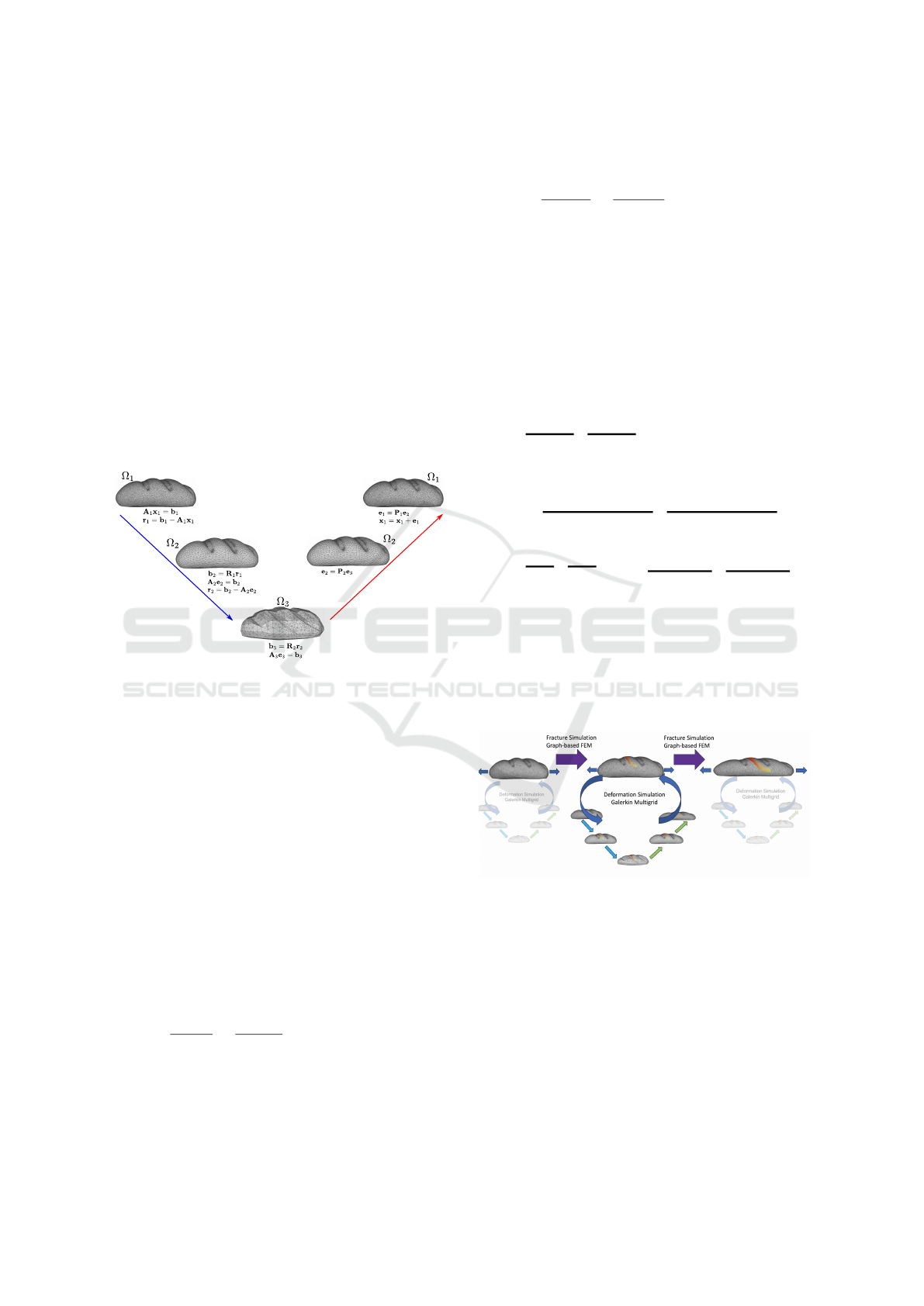
3.2 Galerkin Enhanced Graph-Based
FEM
A Galerkin multigrid method can be conceived as an
iterative method of solving a set of linear systems of
an object mesh by passing it down to increasingly
coarser resolution meshes at multiple levels (Xian
et al., 2019). As shown in Figure 2, the set of lin-
ear systems is defined from finer to coarser resolution
meshes.
For deformation object simulation using FEM, the
discretized linear system equation for the implicit
backward Euler method is written as (Sin et al., 2013)
M + ∆t
2
K
| {z }
A
∆v = ∆t
f
ext
− f
int
− ∆tKv
t
| {z }
b
(3)
where M,K,f
int
& f
ext
denote system mass matrix,
tangent stiffness matrix, internal and external vectors
respectively. v
t
& ∆v denote current velocity incre-
mental velocity at time t. These parameters are con-
structed using element-level parameters.
M =
∑
e∈n
tet
m
e
, K =
∑
e∈n
tet
k
e
f
int
=
∑
e∈n
tet
f
int
e
, f
ext
=
∑
e∈n
tet
f
ext
e
(4)
Galerkin Enhanced Graph-Based FEM for Interactive Fracture and Sculpting Applications
67
where n
tet
is number of tetrahedra in the object mesh.
Initially, the linear system at the finest level
of the Galerkin multigrid method, A
1
x
1
= b
1
(see
Equation 3) is solved using Gauss-Seidel or Jacobi
solver. However, they are stopped much earlier be-
fore convergence is reached. An early stop of these
iterative methods produces a smooth error. The
smooth/residual error is defined as
r
1
= b
1
− A
1
x
1
(5)
Even though the solver is stopped early, the high-
frequency error at each level gets removed quickly,
leaving only low-frequency error in the system. The
low-frequency error is then passed to the next level
containing a coarser resolution mesh. The error then
becomes a high-frequency error at that lower level.
At each timestep, we run an iteration of graph-based
Restriction
Interpolation
Figure 2: Galerkin multigrid deformation simulation:
The system equation is solved in multiple levels using finer
to coarser meshes. At each level, the solver is terminated
much earlier before convergence, and the residual error is
passed to the next level.
FEM to compute the fracture only at the finest level
of the object mesh. This is depicted in Figure 3. To
do this, we calculate normal stress along the edges of
the finest-level mesh using Equation 1. The edge is
considered damaged if the stress value along an edge
exceeds a critical threshold and subsequently uses the
reformulated internal hyper-elastic strain energy den-
sity as given in Equation 2. The graph-based FEM
requires no volume remeshing after fracture i.e., the
initial tetrahedral mesh remains the same throughout
the simulation. However, updated strain energy im-
plies an update of internal force and tangent stiffness
matrix, as explained below. The internal force vector
takes the following form.
f
int
∗
e
=
∂Ψ
e
f rac
∂u
e
=
∂ζ(Ψ
e
)
∂u
e
= ζ
′
(Ψ
e
)Ψ
′
e
= ζ
′
Ψ
′
e
(6)
where f
′
denotes the derivative of function f . In the
last equality, ζ
′
(Ψ
e
) is written as ζ
′
for the sake of
brevity. Similarly, the tangent stiffness matrix can be
expressed as
k
∗
e
=
∂
2
Ψ
e
f rac
∂u
2
e
=
∂(ζ
′
Ψ
′
e
)
∂u
e
= ζ
′′
Ψ
′
e
+ ζ
′
Ψ
′′
e
(7)
where f
int
∗
e
and k
∗
e
are the updated internal force vector
and tangent stiffness matrix for tetrahedral finite ele-
ment. The exact values of ζ
′
and Ψ
′
e
can be obtained
following the algorithms presented in (Mandal et al.,
2023). Finally, using Equation 6, 7 and 4, we can
rewrite the finest level system Equation 3 for Galerkin
enhanced graph-based FEM as follows.
M + ∆t
2
∑
e∈n
tet
k
∗
e
!
| {z }
A
1
∆v
= ∆t
f
ext
−
∑
e∈n
tet
f
int
∗
e
− ∆t
∑
e∈n
tet
k
∗
e
!
v
t
!
| {z }
b
1
=⇒
M + ∆t
2
K
∗
|
{z }
A
1
∆v = ∆t
f
ext
− f
int
∗
− ∆tK
∗
v
t
| {z }
b
1
(8)
Notice that the fracture simulation cycle is not re-
peated on the coarser level meshes as depicted in Fig-
ure 3. However, the various effects of fracture, such
as extra degrees of freedom to the mesh vertices due
to fracture, are propagated to these levels using in-
terpolation matrices. When Equation 8 is solved us-
Figure 3: Galerkin multigrid-based deformation simulation
is combined with graph-based FEM for fracture simulation.
ing some popular solver like Gauss-Seidel or Jacobi
solver, it produces a smooth residual error. The resid-
ual at the finest level is expressed in Equation 5. It is
propagated to the next level using restriction matrix,
R
1
.
b
2
= R
1
r
1
(9)
In more general form, at the coarser level, l + 1, the
residual from level l (similar to Equation 5), is re-
stricted using the restriction matrix, R
l
.
b
l+1
= R
l
r
l
(10)
GRAPP 2025 - 20th International Conference on Computer Graphics Theory and Applications
68

The error update to the vertices of the level l + 1
is computed, again using a few iterations of a popular
solver.
A
l+1
e
l+1
= b
l+1
(11)
where similar to Equation 8, A
l+1
and b
l+1
are the
system matrix and column vector of level l + 1 re-
spectively. Subsequently, the residual for level l + 1
is computed as
r
l+1
= b
l+1
− A
l+1
e
l+1
(12)
After the solver solves the system dynamics at the
coarsest level, the error values at each level are inter-
polated back to the finer level using prolongation or
interpolation matrix P
l
.
e
l
= P
l
e
l+1
(13)
At the finest level, the next position is updated using
x
1
= x
1
+ e
1
.
Since the solver at each level can be stopped early,
and only errors of lower frequency get propagated to
coarser levels, it is not necessary to re-discretize the
system matrix using the Finite Element Method on the
coarser mesh in the Galerkin multigrid method, un-
like pure geometry-based multigrid methods. More-
over, as the whole system is solved in multiple lev-
els, each running just a few iteration loops of some
conventional solver, the entire system runs at an in-
teractive frame rate. Graph-based FEM adds negligi-
ble computational complexity per se while simulating
fracture inside an object mesh. Thus, Galerkin multi-
grid enhanced graph-based FEM is capable of render-
ing fracture in a real-time, interactive manner.
The parameters from the finer to the coarser level
or vice-versa are passed using symmetric restriction
and interpolation matrices at each level l, R
l
and P
l
.
A
l+1
= R
l
A
l
P
l
(14)
Also, R
l
= P
T
l
. The matrices A
l
denote linear systems
matrices at l
th
level. The number of levels depends on
the initial system size and the specific demand of the
application.
The whole process is summarized in Algorithm 2.
If we consider cutting instead of fracture, everything
remains the same except that the user initiates the
crack lines instead of the stress threshold.
A multi-level hierarchy is built by uniformly sam-
pling vertices at various resolutions. Then, the R
l
and P
l
Galerkin projection matrices are set up using
skinning-space coordinates with piece-wise constant
interpolation weights.
3.3 Galerkin Grid Hierarchy and
Projection Matrices
Given an object mesh consisting of n vertices, the
coarser level mesh grids are constructed using the fur-
Algorithm 2: Galerkin enhanced Graph-based FEM.
Set up d-level grid hierarchy, Ω
1
,.. .Ω
d
2: Construct the projection matrices U
1
,.. .U
d
Compute and store the multi-level system matri-
ces A
1
,.. .A
d
4: Compute and store the multi-level external force
vectors b
1
,.. .b
d
for Each element in object mesh do
6: Calculate mesh fracture using Algorithm 1
end for
8: for Each level l do
Update collision and fracture constraints (e.g.
internal force) to A
l
with Equation 14
10: Solve the system equation, A
l
x
l
= b
l
using a
conventional solver (e.g. GS, CG, PCG)
Compute residual, r
l
with Equation 12
12: Pass it down to the next level, l + 1, with
Equation 10
end for
14: Interpolate the solution back to the finest level
with Equation 13
thest point sampling method (Brandt et al., 2018),
which is a special case of the k-means++ algo-
rithm (Arthur and Vassilvitskii, 2007). As depicted
in Figure 4, let us denote the set of all the vertices,
k
g
1
, of the full resolution mesh by Ω
1
. The vertex set,
Ω
2
, of the immediate next level coarser mesh contains
k
g
2
number of vertices and is a subset of Ω
1
.
Ω
2
⊆ Ω
1
, k
g
2
≤ k
g
1
(15)
The set Ω
2
is first initialized with a random vertex
in Ω
1
. Using Dijkstra’s algorithm, we compute the
geodesic distances to Ω
2
of all other vertices. Finally,
the most distant vertex in Ω
1
\Ω
2
is picked and added
to the set Ω
2
. The geodesic distances to the new Ω
2
are updated in the next iteration. This process is re-
peated until the size of Ω
2
becomes k
g
2
. In the same
way, even lower-resolution grids, Ω
3
, Ω
4
, Ω
5
, ... Ω
l
,
are constructed, if required. However, please note that
the meshes at the coarser levels are not explicitly con-
structed. Instead, interpolation and restriction matri-
ces are used to project the parameters of nodes from
a finer mesh to the nodes of a coarser mesh and vice
versa. The full process is explained in the next sec-
tion.
Downsample Downsample
Figure 4: Galerkin grid hierarchy construction. Ω
l
contains
the vertices on the l
th
level grid and Ω
l+1
⊆ Ω
l
.
Each node in a mesh at any level is assumed to
Galerkin Enhanced Graph-Based FEM for Interactive Fracture and Sculpting Applications
69
possess twelve degrees of freedom. The interpolation
between different levels is constructed using Linear
Blending Skinning (LBS).
y
i
=
∑
j
ω
i j
T
j
Y
i
(16)
where y
i
∈ R
3×1
is position of i
th
vertex, T
j
∈ R
3×4
is
the affine transformation matrix of the j
th
control han-
dle, Y
i
∈ R
4×1
is the homogeneous coordinate of the
rest-pose position of vertex i, and ω
i j
is the weight of
handle j to vertex i. Rewriting and rearranging Equa-
tion 16 over all vertices gives the following relation.
Y = Uq (17)
where Y =
y
T
0
,y
T
1
,.. .y
T
n−1
is the position of all ver-
tices at the finest level;
q = [vec(T
0
),vec(T
1
),.. .vec(T
n−1
)] ∈ R
12k×1
de-
notes all the skinning space degrees of freedom; and
U ∈ R
3n×12k
is the linear transformation matrix be-
tween q and Y. Each block of U can be written down
explicitly as U
i j
= ω
i j
Y
T
i
⊗ I
3
∈ R
3×12
where ⊗I
3
is
a Kronecker product with a 3×3 identity matrix. Fol-
lowing the same argument, the interpolation between
multiple coarser levels can be calculated below.
q
l
= U
l
q
l+1
(18)
Finally, the interpolation matrix P for different levels
are defined as P
l
= U
l
. To maintain the symmetry of
the system matrix while using the Galerkin multigrid
projection method, the restriction matrix is set to R
l
=
U
T
l
.
The weight parameters ω
i j
are piecewise constant
weights i.e, ω ∈ {0,1}. These weights introduce more
high-frequency errors in the system. However, as
discussed earlier, the high-frequency errors produced
due to these non-smooth weights get suppressed in
the coarser levels. Further details about the Galerkin
multigrid method for deformation simulation can be
found in (Xian et al., 2019).
4 RESULTS
This section presents multiple simulation examples of
interactive cutting and fracture using our method. We
also compare our method to the existing state-of-the-
art FEM methods developed to simulate deformation
and fracture.
All the experiments presented here are carried out
with an Intel i7-9750H octa-core processor, 16GB
DDR4 RAM, and a single Nvidia RTX 2060 GPU
with 6 GB of graphics memory. All the simulation
examples are parallelized using CUDA. In all our sim-
ulations, the blue nodes on the mesh denote fixed
points.
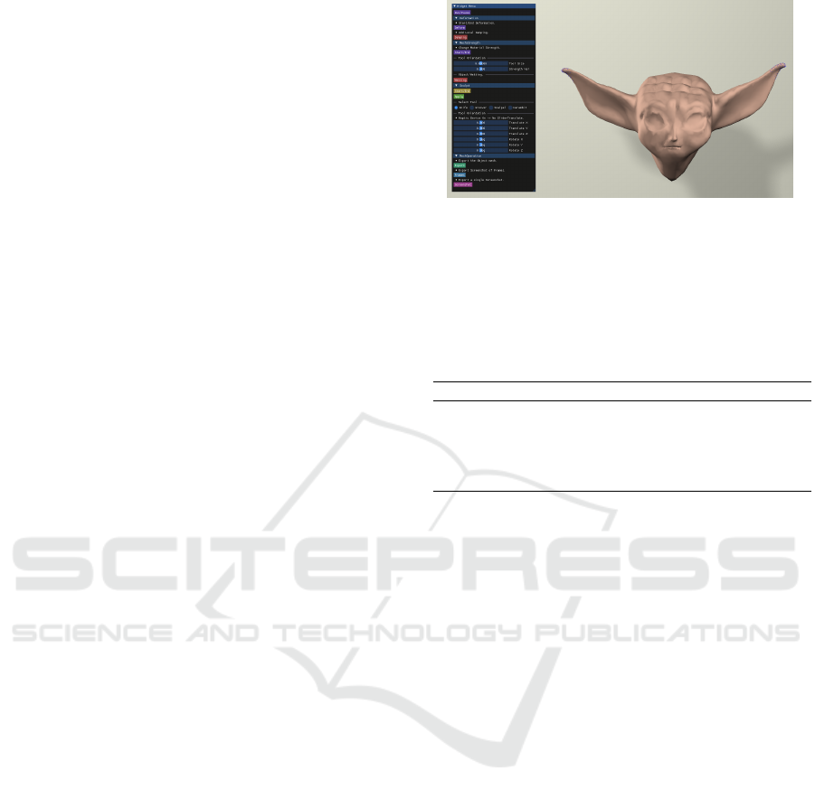
Figure 5: Our Galerkin enhanced graph-based FEM fracture
and cutting simulation algorithm drives an interactive vir-
tual sculpting framework. Here, we show a model sculpted
using our framework.
Parameters and frame per second (fps) values for
each simulation result are presented in Table 1.
Table 1: Parameters for simulation experiments.
Simulation #Tet Grid Setup fps
Armadillo (Fig. 7) 160k 50/1000/all 34.9
Human body (Fig. 6) 40k 50/all 127.2
Sphere (Fig. 14) 34.9k 50/all 118.7
Steak (Fig. 8) 186.1k 50/1000/all 24.7
Charpy test (Fig. 12) 28k 50/all 152.5
4.1 Galerkin Grid Setup
Before presenting the results, we quickly explain the
grid structure of the Galerkin method. All the results
are accompanied by a grid setup depicted as
level
n
/level
n−1
/.. ./level
2
/level
1
/all. It denotes the
number of vertices at each level of the Galerkin grid
mesh, and ‘all’ denotes the vertices of the finest level
input mesh.
We perform a study of the grid structure on vari-
ous parameters as follows. We notice that increasing
the number of levels contributes little to the speed-up
or accuracy of the simulation. We use volume gain
to characterize accuracy in these results. In multigrid
Galerkin, the solver at each level is terminated after
a few fixed user-defined number of steps, even before
the convergence is attained. However, if the number
of these steps is increased, the error gets reduced at
the expense of simulation time. For example, we sim-
ulated a sphere hanging under gravity (see Figure 14)
with a 50/all grid setup. At the finest level, we use a
Gauss-Seidel/Jacobi solver with three cycles, and at
the coarser level, a Conjugate Gradient (CG) solver
with 20 cycles or a direct solver. The simulation runs
at 118.7 frames/sec with a volume error 19%. How-
ever, if the cycles of PCG and CG are increased to
30 and 200, respectively, the simulation runs at 23.8
frames/sec with a volume error of 11%.
GRAPP 2025 - 20th International Conference on Computer Graphics Theory and Applications
70
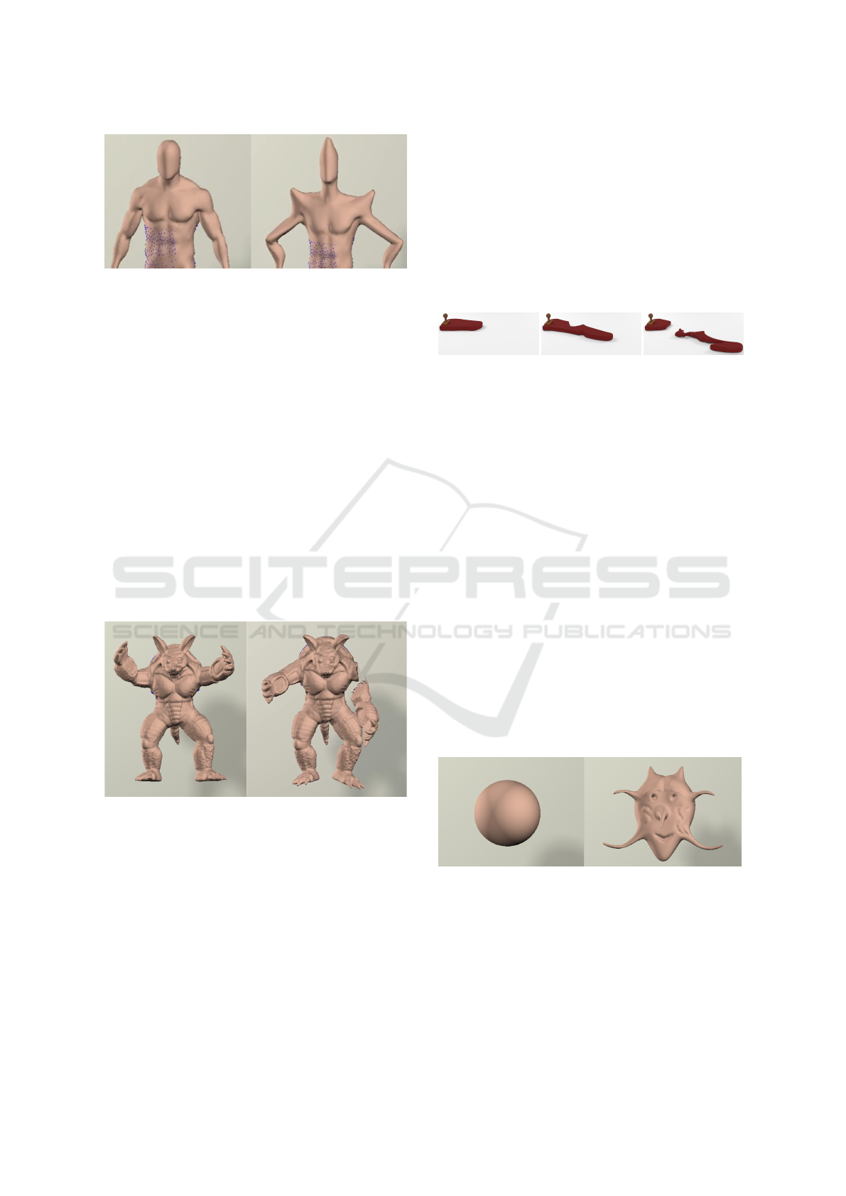
Figure 6: Illustration of the original (left) and deformed hu-
man body model for Galerkin multigrid method (right).
4.2 Deformation and Cutting
Deformation on a human body mesh using Galerkin-
enhanced graph-based FEM is shown in Figure 6. The
human body mesh comprises 40k tetrahedra, and the
simulation runs at 127.2 frames/sec, with a grid set up
of 50/all.
Is-XFEM (Mandal et al., 2022a) also uses multi-
resolution meshes to achieve interactive deformation
and cutting. We compare our method to the im-
plementation of Is-XFEM presented by Mandal et
al. (Mandal et al., 2022a). For the sake of fair com-
parison, unlike the original implementation, the Is-
XFEM method is run on a single thread without hap-
tic feedback. The Is-XFEM simulation runs at 4.1
frames/sec when no cut is present and 3.5 frames/sec
when one cut is introduced. The frame rate keeps on
decreasing as the number of cuts increases.
Figure 7: Illustration of an original (left) and fractured
(right) armadillo mesh.
In Figure 7, we render the fracture of an armadillo
mesh using Galerkin multigrid method augmented
with graph-based FEM. In the figure, the left arm of
the armadillo is detached from its body when pulled
by the user. The armadillo model consists of 160k
tetrahedra and runs at 34.9 frames/sec with a grid
setup of 50/1000/all. This same cutting simulation of
the armadillo mesh requires 1.4 sec/frame if Is-XFEM
is used. Therefore Galerkin multigrid with graph-
based FEM is around ×25 faster than Is-XFEM.
4.3 Fracture Simulation
In Figure 8, we simulate the fracture of a steak
clamped at one end and pulled at the other. The steak
mesh consists of 186.1k tetrahedra. Galerkin multi-
grid method combined with graph-based FEM ren-
ders the simulation at 24.7 frames/sec with a grid set
up of 50/1000/all. The simulation stays physically
plausible and runs at an interactive rate even for such
a high-resolution mesh.
Figure 8: A piece of steak consisting of 186.1k tetrahedra is
torn apart from pulling at one end. This is simulated using
Galerkin-enhanced graph-based FEM. Galerkin-enhanced
graph-based FEM runs at 24.7 frames/sec.
4.4 Interactive Fracture and Cutting
Simulation
We use Galerkin multigrid to accelerate the deforma-
tion simulation while using graph-based FEM to re-
solve the fracture on the finest level of the mesh. This
allows us to simulate fracture and cutting at interac-
tive rates.
We develop a virtual sculpting application using
our method. Figure 5 shows a screenshot of our ap-
plication. The application provides a user with vari-
ous tools for mesh manipulation and simple naviga-
tional components to orient those. These sculpting
tools include knives, deformation brushes, and an-
choring tools. We used our application to create vari-
ous sculpting examples and conducted a user study to
gauge its efficacy. We present these results in the next
section.
Figure 9: Original (left) and sculpted (right) Sphere model
using Galerkin multigrid framework.
Our interactive virtual sculpting application can
handle multiple sculpting operations performed on an
object mesh in real-time. At the end of the sculpting
operations, the volumetric tetrahedral and visualiza-
tion triangular mesh are affected. Users can save, ex-
port, or import any of these sculpted meshes, whether
tetrahedral or triangular, for using them in the same
Galerkin Enhanced Graph-Based FEM for Interactive Fracture and Sculpting Applications
71
or other applications. Moreover, after sculpting, our
method always generates a water-tight visualization
mesh convenient for further use in different applica-
tions.
In Figure 9, an amateur volunteer sculpted a scary
mask starting from a simple sphere model using our
application. In Figure 5, another user sculpted a
model starting from a simple sphere mesh.
4.5 Comparison Study
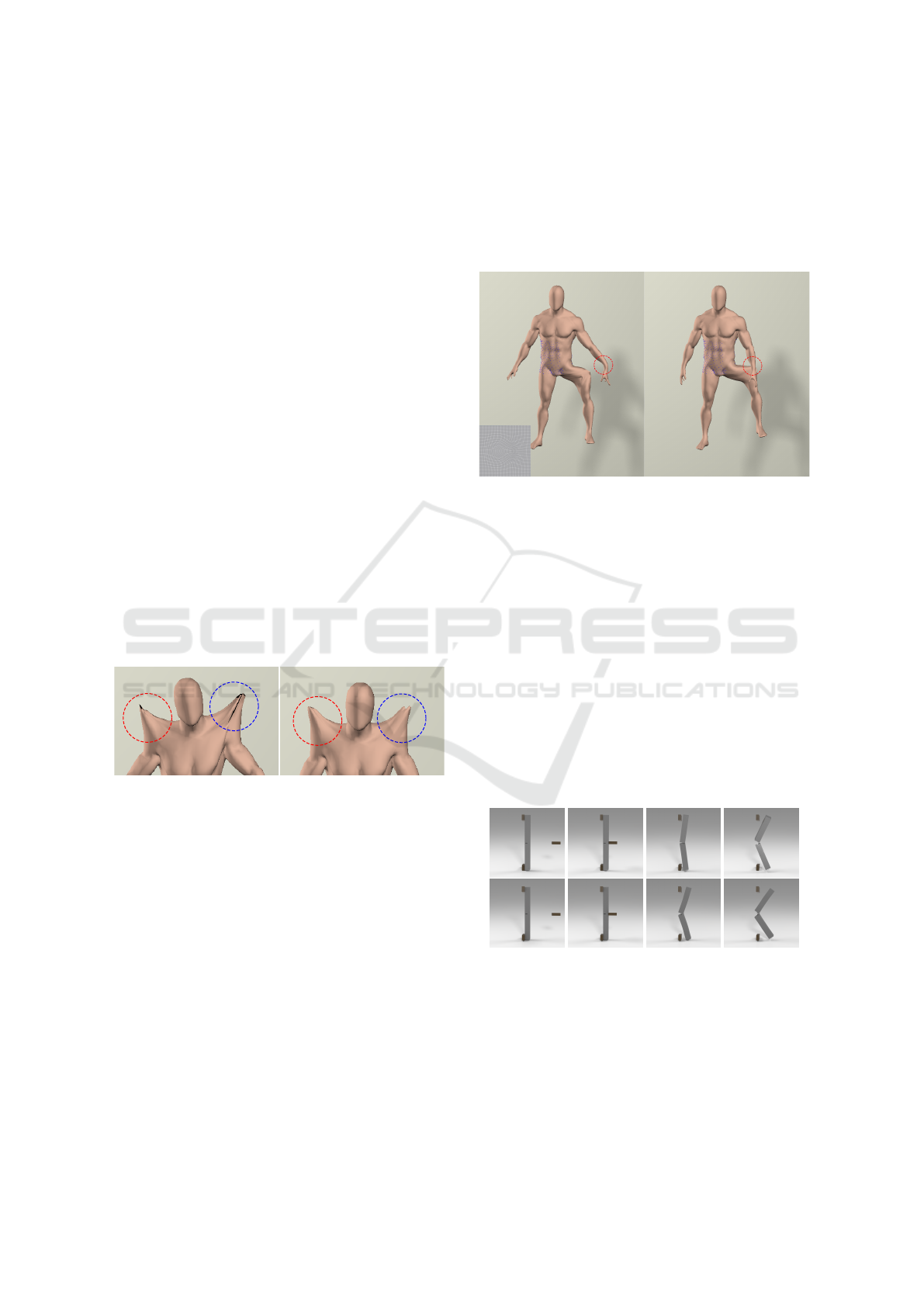
Figure 10 compares the sculpting generated using two
distinct methods. On the left side of the figure, we ob-
serve the deformed shapes of different limbs of a hu-
man body, obtained through a solely geometry-driven
technique such as Blender’s grab brush (Blender
Foundation, 2023). On the right side, we present sim-
ilar results with the physics-based sculpting approach,
developed using our Galerkin-enhanced graph-based
FEM.
The illustration distinctly highlights the merits of
our physics-based sculpting method for improving
volume preservation, even without any explicit input
regarding the surface structure of the object mesh.
Better volume preservation results in sculpted shapes
that are faithful to their original forms. In contrast,
traditional geometry-based tools tend to collapse the
volume and generate unrealistic structures.
Figure 10: The left column shows the deformation re-
sults of a human body using a geometry-driven technique
Blender’s grab brush. The right column illustrates the same
deformations using our physics-based Galerkin-enhanced
graph-based FEM. Notice that our physically-based sculpt-
ing framework improves local volume preservation.
Kelvinlets, as introduced in (De Goes and James,
2017), are fundamental solutions of linear elasticity
for singular loads. They enable the real-time render-
ing of physically accurate mesh deformations. How-
ever, the deformation generated by Kelvinlets moves
as if it is embedded in an infinite elastic continuum.
Consequently, these embedded deformations some-
times produce unintended and undesirable non-local
interactions. For example, in Figure 11 (left), ob-
serve the deformation of the left leg of a human body
mesh. It is rendered by applying a Kelvinlet kernel
as depicted in the inset. As can be seen, there are
unrealistic nonlocal deformations induced in the left
hand of the body (red circled), despite being geodesi-
cally far away from the deformed leg. In contrast, our
Galerkin-enhanced graph-based FEM does not suffer
from this limitation and is capable of rendering local
deformation accurately as illustrated on the right side
of Figure 11.
Figure 11: Left leg of human body mesh is deformed by
applying a Kelvinlet kernel as depicted in the inset (left).
However, it produces undesirable and non-local deforma-
tion to the geodesically distant components of the body (red
circled). In contrast, our Galerkin-enhanced graph-based
FEM can render local deformation accurately.
4.6 Validation Results
A Charpy Impact test is a standard experiment per-
formed in an undergraduate strength of materials lab-
oratory. We simulate the Charpy Impact test using our
method and with regular graph-based FEM. In the ex-
periment, a notched steel specimen is held on the two
ends, and a swinging pendulum hits it in the middle,
as depicted in the top row of Figure 12. After the col-
lision, the specimen gets split into two disjoint pieces.
The same test is performed using normal graph-based
Figure 12: Charpy Impact Test: The top row shows the
simulation with Galerkin-enhanced graph-based FEM and
the bottom row with normal graph-based FEM. The left-
most image in each row shows the configuration of the
Charpy test. When hit by a swinging pendulum (shown with
the moving square block), the notched specimen gets split
into two pieces.
FEM as depicted in the bottom row of Figure 12. As
evident from the images graph-based FEM has better
GRAPP 2025 - 20th International Conference on Computer Graphics Theory and Applications
72

at preserving finer details and rendering correct de-
formation. The notched bar consists of 28k tetrahe-
dra. While Galerkin multigrid method runs at 152.5
frames/sec with a grid set up of 50/all, regular graph-
based FEM runs at around 4.7 frames/sec. In Fig-
ure 13, we plot the load-crack mouth opening dis-
placement (CMOD) curve obtained from our simu-
lated Charpy impact test experiment. The solid blue
line with a shaded envelope is the experimental load-
CMOD curve from real physical experiments and the
dotted magenta line represents the same curve derived
from the XFEM simulation, as reported by (Areias
and Belytschko, 2005). The dashed red line and
green dashed-dotted line denote the plot for our sim-
ulation set-up using Galerkin-enhanced graph-based
FEM and normal graph-based FEM respectively. The
figure shows that our experimental results closely fol-
low the real-world laboratory experiment results.
Figure 13: The plot compares the load-crack mouth open-
ing displacement (CMOD) curve of the simulated Charpy
impact test with ground truth curves from actual laboratory
experiments.
5 DISCUSSION AND USER
EXPERIMENT
Even though our method runs much faster than the
existing state-of-the-art deformation simulation tech-
niques, the gain in speed comes at the cost of some
accuracy. We compare the accuracy of the Galerkin-
enhanced graph-based FEM with standard FEM with
different constitutive models in terms of volume gain
(of an incompressible material) as shown in Table 2.
We use a high Poisson ratio (≈ 0.48) for our ex-
periment. In Figure 14, we simulate a sphere that
hangs under gravity and is hinged at the top. This
hanging sphere is simulated with different algorithms
using various hyper-elastic strain energies as ex-
plained in Table 2. As evident from the table, com-
pared to our method, only Co-rotational FEM (Irv-
ing et al., 2004) performs poorly in terms of vol-
ume preservation. However, more recent constitutive
models used in FEM deformation simulation like In-
vertible Principal-Stretch Material design (Xu et al.,
2015) (Sin et al., 2013), stable Neo-Hookean (Smith
et al., 2018) introduce less error than our method.
Thus if volume gain is used as a metric for accu-
Figure 14: A sphere mesh is fixed at the top and hangs under
gravity.
racy for deformation simulation, then we see that our
method clearly trades some accuracy to gain speed
of computation. This is a result of the multi-scale
approximate solve of the system dynamics in the
Galerkin multigrid method.
Table 2: Volume gain in different existing consecutive mod-
els using various hyper-elastic strain energies.
Method Vol. Gain
Co-rot. FEM (Irving et al., 2004) 85%
Inv. N-Hkn (Sin et al., 2013) 3.2%
Inv. StVK (Sin et al., 2013) 10.7%
Stb. N-Hkn (Smith et al., 2018) 4.3%
Our Method (Xian et al., 2019) 19%
5.1 User Study
We conducted a user study to evaluate our interac-
tive application for all the virtual sculpting operations
available in it. The data collection methodology was
suitably evaluated and approved by an ethics commit-
tee of Indian Institute of Technology Bombay, India
and all participants’ data was suitably anonymized.
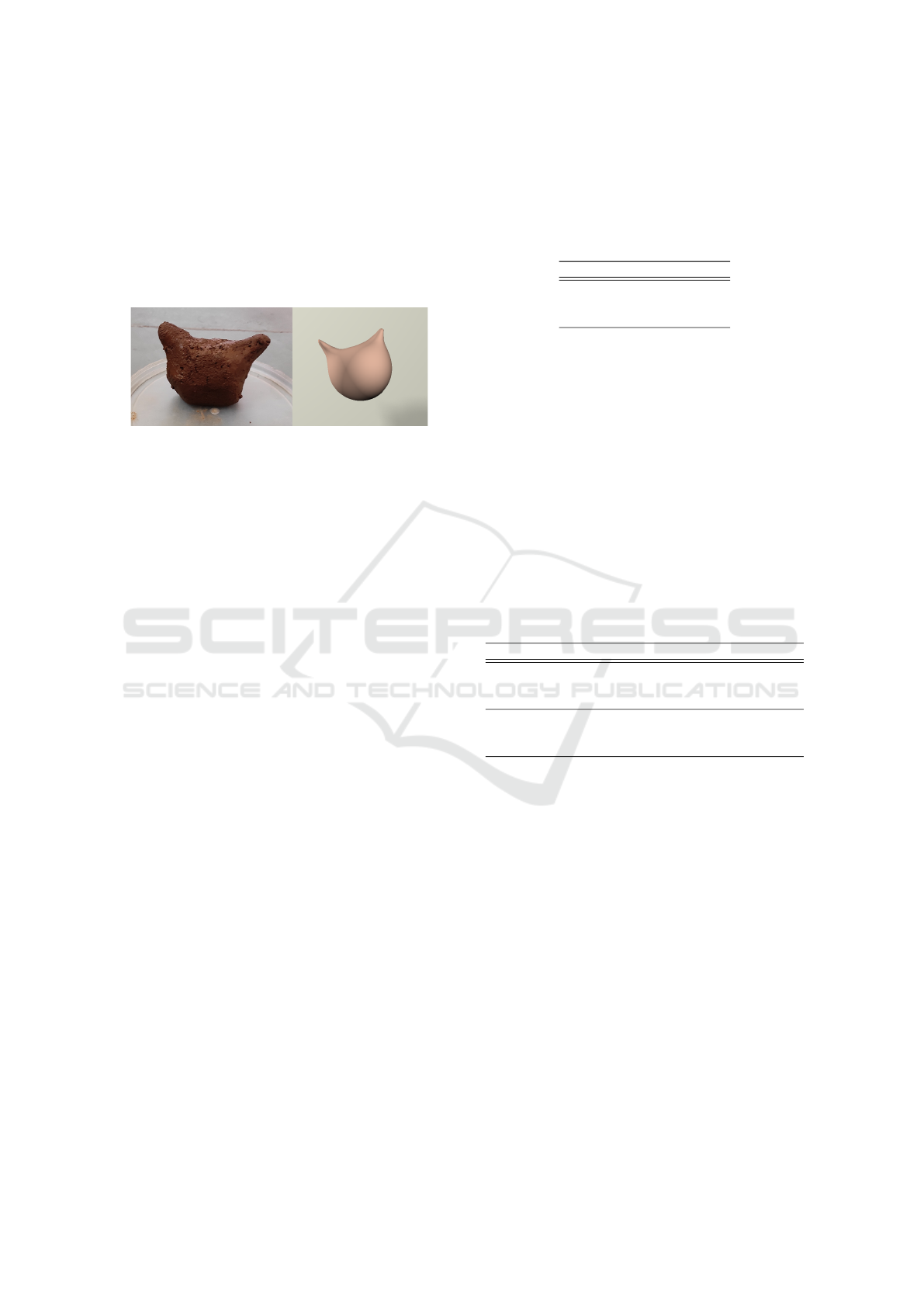
Figure 15: Making a dent on a real clay ball (left) and a
virtually simulated ball (right).
We recruited ten participants (aged between 25 to
35 years) to take part in our experiments. None of the
participants reported any ailment. All the participants
have normal or corrected-to-normal vision and during
the experiment, they use their dominant hand.
First, we give a brief demo of our virtual sculpt-
ing framework to the participants. At the start of the
experiment, the participants are asked to mould a ball
Galerkin Enhanced Graph-Based FEM for Interactive Fracture and Sculpting Applications
73
of clay with a stick and knife to get acquainted with
real-world sculpting. The user then puts his/her elbow
on the handle of the chair and holds the mouse to in-
teract with the virtual environment. Figure 15 depicts
the deformation of a real clay sphere and compares
it with a similar deformation, simulated on a virtual
sphere using our framework. Similar results are de-
picted in Figure 16.
Figure 16: Shapes made by participants using a real clay
ball (left) and a virtually simulated ball (right).
During the study, we asked all the participants
to use the deformation and cutting tools on a sphere
mesh. Moreover, the participants are also asked to de-
form and cut the same sphere mesh using Blender. In
order to ensure a fair comparison, we prohibited the
participants from utilizing any other tools available in
Blender, with the exception of the elastic deform and
cutting knife functionalities. To eliminate any bias in-
duced by the order of use of the two systems, half of
the participants are exposed to Blender first and then
our framework, while for the other half, the sequence
is reversed. After finishing the experiments, the par-
ticipants are asked to rate both of the frameworks on
a scale of 1 (very poor) to 10 (very good) in terms of
the following three parameters.
• Physical realism: How closely does the interac-
tion with the virtual material in our sculpting ap-
plication match the interaction with real clay?
• Ease of use: How easy and intuitive is it to use the
sculpting tools to manipulate the virtual material
or object in our sculpting application?
• Responsiveness: While interacting with the ob-
ject during the sculpting, is there any lag between
the interaction being done and the visual update?
The t-test (Rice, 2006) is a commonly used tool
to analyze whether the differences between groups of
data are statistically significant. In our experiment,
we first ascertain if the user opinions differed signif-
icantly between the two groups, (a) those who used
Blender first and (b) those who used our framework
first. The null hypothesis in this t-test the user rating
patterns indicate that there is a significant difference
between the sculpting experience in Blender and our
framework, for each of the measured parameters. If
the p-value is below a certain threshold (0.05 is a uni-
versally accepted criterion), the null hypothesis is re-
jected. The p-value for each parameter is reported in
Table 3. In all cases, the p-value is below 0.05, which
implies that both strategies are equally effective.
Table 3: P-value for the t-test.
Parameter p-value
Physical realism 0.0071
Ease of use 0.0383
Responsiveness 0.0001
The mean, median, and standard deviation of the
ratings of the user feedback are listed in Table 4. As
evident from the Table, the users rate their experience
using our application for virtual sculpting very favor-
ably. Moreover, the low value of standard deviation
denotes a lower disagreement of opinion among users.
Blender is a professional-grade tool with years of de-
velopment experience, and our application’s ratings
match it closely for the virtual sculpting task. We be-
lieve that our framework preserves physical plausibil-
ity and has the potential to deliver satisfactory results
for various kinds of shape modeling and design tasks.
Our method is also valuable for computing physically
plausible haptic feedback in gaming.
Table 4: Mean, median, and standard deviation of user feed-
back from the study.
Method Parameter Mean Median Std
Ours Physical realism 8.45 8.75 0.43
Ease of use 8.85 9.00 0.61
Responsiveness 9.35 9.00 0.58
Blender Physical realism 9.25 9.00 0.26
Ease of use 9.75 10.0 0.26
Responsiveness 9.90 10.0 0.22
6 LIMITATIONS AND FUTURE
WORK
Our work introduces a Galerkin-enhanced graph-
based FEM algorithm for interactive, real-time frac-
ture and cutting simulation. Our method can ren-
der fractures for extremely high-resolution meshes at
an interactive rate without any computational over-
head, regardless of the number of cracks introduced
within the object mesh. Using this algorithm, we
develop an interactive virtual sculpting framework
and present various dynamic simulation scenarios to
demonstrate its effectiveness and usability. We com-
pare our method with existing techniques and real-
world experiments to evaluate its performance. Our
method holds promise for various applications, in-
cluding 3D virtual surgery, asset creation, and more.
Our method enables the interactive simulation of
GRAPP 2025 - 20th International Conference on Computer Graphics Theory and Applications
74

fractures in high-resolution meshes; however, it has
certain limitations in its current form. To achieve real-
time performance, we prioritize computational effi-
ciency over accuracy in volume preservation. As a
result, the algorithm faces challenges in generating
and maintaining intricate crack patterns. A promising
future research direction is enhancing volume preser-
vation accuracy while maintaining real-time perfor-
mance. Implementing volume correction techniques
at each Galerkin grid level could be a potential ap-
proach to address this limitation.
REFERENCES
Areias, P. M. A. and Belytschko, T. (2005). Analysis
of three-dimensional crack initiation and propagation
using the extended finite element method. Interna-
tional Journal for Numerical Methods in Engineering,
63(5):760–788.
Arthur, D. and Vassilvitskii, S. (2007). K-means++: The
advantages of careful seeding. In Proceedings of the
Eighteenth Annual ACM-SIAM Symposium on Dis-
crete Algorithms, SODA ’07, page 1027–1035, USA.
Society for Industrial and Applied Mathematics.
Bargteil, A. W., Wojtan, C., Hodgins, J. K., and Turk, G.
(2007). A finite element method for animating large
viscoplastic flow. ACM Trans. Graph., 26(3):16–es.
Blender Foundation (2023). Blender 3.6.4 lts. https://www.
blender.org/ Last accessed on 2-10-2023.
Bouaziz, S., Martin, S., Liu, T., Kavan, L., and Pauly, M.
(2014). Projective dynamics: Fusing constraint pro-
jections for fast simulation. ACM Transactions on
Graphics, 33(4).
Brandt, C., Eisemann, E., and Hildebrandt, K. (2018).
Hyper-reduced projective dynamics. ACM Transac-
tions on Graphics, 37(4).
Chen, Z., Yao, M., Feng, R., and Wang, H. (2014). Physics-
inspired adaptive fracture refinement. ACM Trans.
Graph., 33(4).
Chentanez, N., M
¨
uller, M., and Macklin, M. (2016). Real-
time simulation of large elasto-plastic deformation
with shape matching. In Proceedings of the ACM SIG-
GRAPH/Eurographics Symposium on Computer Ani-
mation, SCA ’16, page 159–167, Goslar, DEU. Euro-
graphics Association.
Chitalu, F. M., Miao, Q., Subr, K., and Komura, T. (2020).
Displacement-correlated xfem for simulating brittle
fracture. Computer Graphics Forum, 39(2):569–583.
De Goes, F. and James, D. L. (2017). Regularized kelvin-
lets: Sculpting brushes based on fundamental solu-
tions of elasticity. ACM Trans. Graph., 36(4).
Fan, L., Chitalu, F. M., and Komura, T. (2022). Simulat-
ing brittle fracture with material points. ACM Trans.
Graph., 41(5).
Hahn, D. and Wojtan, C. (2015). High-resolution brittle
fracture simulation with boundary elements. ACM
Trans. Graph., 34(4).
Hahn, D. and Wojtan, C. (2016). Fast approximations for
boundary element based brittle fracture simulation.
ACM Trans. Graph., 35(4).
Hirota, K., Tanoue, Y., and Kaneko, T. (2000). Simulation
of three-dimensional cracks. The Visual Computer,
16:371 – 378.
Irving, G., Teran, J., and Fedkiw, R. (2004). Invert-
ible finite elements for robust simulation of large de-
formation. In Proceedings of the 2004 ACM SIG-
GRAPH/Eurographics Symposium on Computer An-
imation, SCA ’04, pages 131–140, Goslar Germany,
Germany. Eurographics Association.
James, D. L. and Pai, D. K. (1999). Artdefo: Accurate
real time deformable objects. In Proceedings of the
26th Annual Conference on Computer Graphics and
Interactive Techniques, SIGGRAPH ’99, page 65–72,
USA. ACM Press/Addison-Wesley Publishing Co.
Khodabakhshi, P., Reddy, J. N., and Srinivasa, A. (2016).
Grafea: a graph-based finite element approach for
the study of damage and fracture in brittle materials.
Meccanica, 51:3129 – 3147.
Kim, T., De Goes, F., and Iben, H. (2019). Anisotropic elas-
ticity for inversion-safety and element rehabilitation.
ACM Trans. Graph., 38(4).
Koschier, D., Bender, J., and Thuerey, N. (2017). Robust
extended finite elements for complex cutting of de-
formables. ACM Trans. Graph., 36(4).
Macklin, M. and M
¨
uller, M. (2013). Position based fluids.
ACM Transactions on Graphics, 32(4).
Mandal, A., Chaudhuri, P., and Chaudhuri, S. (2022a).
Interactive physics-based virtual sculpting with hap-
tic feedback. Proceedings of the ACM on Computer
Graphics and Interactive Techniques, 5(1).
Mandal, A., Chaudhuri, P., and Chaudhuri, S. (2022b).
Simulating fracture in anisotropic materials contain-
ing impurities. MIG ’22, New York, NY, USA. Asso-
ciation for Computing Machinery.
Mandal, A., Chaudhuri, P., and Chaudhuri, S. (2023).
Remeshing-free graph-based finite element method
for fracture simulation. Computer Graphics Forum,
42(1):117–134.
Molino, N., Bao, Z., and Fedkiw, R. (2004). A virtual node
algorithm for changing mesh topology during simula-
tion. In ACM SIGGRAPH 2004 Papers, SIGGRAPH
’04, page 385–392, New York, NY, USA. Association
for Computing Machinery.
M
¨
uller, M. (2008). Hierarchical position based dynamics.
In Workshop on Virtual Reality Interactions and Phys-
ical Simulations.
M
¨
uller, M. and Gross, M. (2004). Interactive virtual ma-
terials. In Proceedings of Graphics Interface 2004,
GI ’04, page 239–246, Waterloo, CAN. Canadian
Human-Computer Communications Society.
O’Brien, J. F., Bargteil, A. W., and Hodgins, J. K. (2002).
Graphical modeling and animation of ductile fracture.
ACM Trans. Graph., 21(3):291–294.
O’Brien, J. F. and Hodgins, J. K. (1999). Graphical model-
ing and animation of brittle fracture. In Proceedings
of the 26th Annual Conference on Computer Graph-
ics and Interactive Techniques, SIGGRAPH ’99, page
Galerkin Enhanced Graph-Based FEM for Interactive Fracture and Sculpting Applications
75

137–146, USA. ACM Press/Addison-Wesley Publish-
ing Co.
Overby, M., Brown, G. E., Li, J., and Narain, R. (2017).
Admm ⊇ projective dynamics: Fast simulation of hy-
perelastic models with dynamic constraints. IEEE
Transactions on Visualization and Computer Graph-
ics, 23(10):2222–2234.
Pfaff, T., Narain, R., de Joya, J. M., and O’Brien, J. F.
(2014). Adaptive tearing and cracking of thin sheets.
ACM Trans. Graph., 33(4).
Rice, J. A. (2006). Mathematical Statistics and Data Anal-
ysis. Belmont, CA: Duxbury Press., third edition.
Sin, F. S., Schroeder, D., and Barbi
ˇ
c, J. (2013). Vega: Non-
linear fem deformable object simulator. Computer
Graphics Forum, 32(1):36–48.
Smith, B., Goes, F. D., and Kim, T. (2018). Stable neo-
hookean flesh simulation. ACM Trans. Graph., 37(2).
Stomakhin, A., Howes, R., Schroeder, C., and Teran, J. M.
(2012). Energetically consistent invertible elasticity.
In Proceedings of the 11th ACM SIGGRAPH / Eu-
rographics Conference on Computer Animation, EU-
ROSCA’12, pages 25–32, Aire-la-Ville, Switzerland,
Switzerland. Eurographics Association.
Stomakhin, A., Schroeder, C., Chai, L., Teran, J., and Selle,
A. (2013). A material point method for snow simula-
tion. ACM Trans. Graph., 32(4).
Terzopoulos, D. and Fleischer, K. (1988). Modeling inelas-
tic deformation: Viscolelasticity, plasticity, fracture.
SIGGRAPH Comput. Graph., 22(4):269–278.
Wicke, M., Ritchie, D., Klingner, B. M., Burke, S.,
Shewchuk, J. R., and O’Brien, J. F. (2010). Dy-
namic local remeshing for elastoplastic simulation.
In ACM SIGGRAPH 2010 Papers, SIGGRAPH ’10,
New York, NY, USA. Association for Computing Ma-
chinery.
Wolper, J., Chen, Y., Li, M., Fang, Y., Qu, Z., Lu, J., Cheng,
M., and Jiang, C. (2020). Anisompm: Animating
anisotropic damage mechanics. ACM Trans. Graph.,
39(4).
Wolper, J., Fang, Y., Li, M., Lu, J., Gao, M., and Jiang, C.
(2019). Cd-mpm: Continuum damage material point
methods for dynamic fracture animation. ACM Trans.
Graph., 38(4).
Xian, Z., Tong, X., and Liu, T. (2019). A scalable
galerkin multigrid method for real-time simulation of
deformable objects. ACM Transactions on Graphics,
38(6).
Xu, H., Sin, F., Zhu, Y., and Barbi
ˇ
c, J. (2015). Nonlinear
material design using principal stretches. ACM Trans-
actions on Graphics, 34(4).
GRAPP 2025 - 20th International Conference on Computer Graphics Theory and Applications
76
