
Towards the Model-Driven Development of Adaptive Cloud Applications
by Leveraging UML-RT and Container Orchestration
Mufasir Muthaher Mohammed, Karim Jahed, Juergen Dingel and David Lamb
School of Computing, Queen’s University, Kingston, Canada
Keywords:
Model-Driven Development, Adaptation, UML-RT, Cloud Applications, Container Orchestration.
Abstract:
Containers are self-contained units of code that can be executed in various computing environments. Container
orchestration tools such as Kubernetes (K8s) assist in deploying, scaling, and managing containers, permit-
ting alterations to the execution platform (environment) at runtime. Container orchestration and model-driven
engineering (MDE) both offer concepts, techniques, and tools that facilitate the realization of self-adaptation
capabilities. Yet, their joint use for the design, implementation, and maintenance of adaptive cloud applications
appears to be underexplored. This paper presents the results of our investigation of how container orchestra-
tion can complement an extension of existing MDE techniques (based on UML-RT, a UML 2 profile) for the
effective design, implementation, and maintenance of adaptive cloud applications. We will describe an ap-
proach and toolchain for automatically generating and deploying a fully containerized distributed application
from a UML-RT model and leveraging both model- and platform-level dynamic adaptation and failure recov-
ery capabilities to allow the application to respond to runtime changes to the requirements or failures. The
application of the approach with the help of a prototype implementation of our toolchain to an exemplar is
described. The evaluation results show the feasibility and effectiveness of the approach.
1 INTRODUCTION
The industrial interest in self-adapting software sys-
tems is on the rise. Anecdotal evidence for this claim
can be found on the web, but stronger support can
also be found in the literature (e.g., (Beyer et al.,
2016), (Spyker, 2020), (Weyns et al., 2023)). A re-
cent survey (Weyns et al., 2023) finds that large parts
of the industry already make significant use of self-
adaptation to, e.g., increase system utility and de-
crease costs via auto-scaling, auto-tuning, or moni-
toring. A lot of this use is enabled by cloud comput-
ing in general and containerization in particular. E.g.,
Kubernetes is the technology most frequently men-
tioned in (Weyns et al., 2023), followed by AWS Elas-
tic Cloud, RedHat OpenShift, and DynaTrace.
The industry appears positive about self-
adaptation but also reports on significant challenges
and calls for further research. Many of these chal-
lenges are caused by, e.g., a lack of design guidelines,
the need to support different system views, and
increasing complexity (Weyns et al., 2023). In gen-
eral, concepts, techniques, and tools from software
architecture and MDE seem particularly relevant to
study and address these challenges.
Our work explores the extension of existing MDE
support for real-time embedded systems via UML-
RT, a profile of UML 2, for the model-driven develop-
ment of distributed, cloud-based applications capable
of adapting to, e.g., runtime changes in the require-
ments the application is to satisfy and the availability
of computing resources. Apart from leveraging UML-
RT’s support for dynamic changes to the structure
and behavior of the model, our work also takes ad-
vantage of the capabilities of container management
platforms such as K8s to dynamically adjust the com-
puting resources allocated to the application and deal
with node failure. In light of the state-of-the-art, our
work addresses the following research questions:
RQ1: Is it possible to adapt existing UML-RT-based
MDE approaches to obtain an MDE approach and
toolchain that allows the model-driven development
of containerized applications deployable on local and
remote clusters?
RQ2: Is it possible to further adapt this MDE ap-
proach and toolchain for containerized applications
so that the failure recovery capabilities of existing
container management platforms are leveraged?
RQ3: Is it possible to extend this MDE approach and
toolchain to support dynamic changes to the appli-
cation requirements via adaptation on a) the model-
level and b) the platform-level?
Our contributions lie in the way these questions
are answered and how our answers are evaluated. In
52
Mohammed, M. M., Jahed, K., Dingel, J. and Lamb, D.
Towards the Model-Driven Development of Adaptive Cloud Applications by Leveraging UML-RT and Container Orchestration.
DOI: 10.5220/0013148000003896
In Proceedings of the 13th International Conference on Model-Based Software and Systems Engineering (MODELSWARD 2025), pages 52-63
ISBN: 978-989-758-729-0; ISSN: 2184-4348
Copyright © 2025 by Paper published under CC license (CC BY-NC-ND 4.0)

particular, we describe an exemplar, i.e., an example
of a more complex, distributed, cloud-based software
application that benefits from the adaptation capabili-
ties our work targets, and use it for evaluation.
After reviewing the most relevant background and
related work (Section 2), we describe the exemplar
(Section 3), and then our approach and its implemen-
tation in a prototype toolchain (Section 4). Then,
the evaluation steps and results are summarized (Sec-
tion 5), followed by a discussion on threats to validity
(Section 6). The conclusion provides a summary and
opportunities for future work (Section 7).
2 BACKGROUND
UML-RT. UML-RT is a profile of UML 2 for the
model-driven development of (soft) real-time, embed-
ded applications. It is a successor of the ROOM ap-
proach (Selic et al., 1992), heavily influenced the de-
sign of UML 2 and helped make UML 2 more suitable
for the description of software architectures (Selic,
2006). E.g., the capsule diagram in Fig. 4 shows
two capsule instances (pinger and ponger) with a sin-
gle connector. Capsule behavior is described using
state machines that exchange messages via connec-
tors. UML-RT has a long track record of industrial
use in a range of domains (Herzberg, 1999; Gao et al.,
2004), strong foundations (von der Beeck, 2006; Leue
et al., 2008; Posse and Dingel, 2016) and is supported
by open-source (e.g., Papyrus-RT, ETrice, HCL De-
vOps Code RealTime) and commercial tools (IBM
RSARTE, HCL DevOps Model RealTime). It has
strong similarities with other ‘component & connec-
tor’ architectural description languages (Butting et al.,
2017) and Hewitt’s actor model (Agha, 1985) that un-
derlies several distributed system languages currently
in widespread use, such as Akka (Roestenburg et al.,
2016) and Erlang (Cesarini and Thompson, 2009).
Like UML 2, UML-RT does not prescribe the de-
tails of how capsules and connectors are realized. Ex-
isting tooling implements single- or multi-threaded
C
++
code, but other realizations are possible. Our
work leverages this generality and also allows the
model to be viewed as a distributed application ex-
ecuting on a local or remote K8s cluster.
Cloud Computing. Cloud services provide on-
demand access to resources such as storage and com-
puting power via the Internet. It enhances availability,
agility, and scalability through on-demand provision-
ing. Cloud services vary in access and control, with
Infrastructure as a Service (IaaS) allowing users to
manage infrastructure, Software as a Service (SaaS)
providing access to software, and Platform as a Ser-
vice (PaaS) offering a balance between IaaS and SaaS.
Containerization. Containerization allows the
packaging of software components for easy deploy-
ment on any node, irrespective of the environment,
as long as the container runtime is accessible. This
enhances failure recovery and resource utilization in
deployment frameworks.
Container Orchestration. Container orchestra-
tion (Casalicchio, 2019) automates the management
of containerized applications. Platforms like Ku-
bernetes (Burns et al., 2019) handle tasks such as
provisioning, deploying, scaling, and networking
containers across nodes. These platforms oper-
ate across the IaaS and PaaS spectrum, offering
adaptation capabilities like redeployment, platform
modification, and resource management.
Cloud-Native Adaptation. Cloud-native adapta-
tion leverages cloud platforms for elasticity, load
balancing, and on-demand provisioning, enabling
dynamic resource scaling to optimize performance
based on varying workloads. We aim to offer SaaS-
type encapsulation of cloud resources while ensuring
its effective use through container orchestration.
MDE for Adaptive Systems. The use of modeling
in the context of adaptive systems is broad (Weyns,
2020) and includes architecture description lan-
guages (Kramer and Magee, 2007; Garlan et al.,
2004; Kahani et al., 2017); metamodeling, domain-
specific languages (DSLs) (Alfonso et al., 2021; Vo-
gel and Giese, 2014); model transformation, model
analysis, formal specification and verification (Brad-
bury et al., 2004); models at runtime (Bencomo et al.,
2019); modeling of requirements, variability, uncer-
tainty, features, goals, and performance, model-based
testing (Pueschel et al., 2013); and design space ex-
ploration. In accordance with the taxonomy dimen-
sions identified in surveys (Salehie and Tahvildari,
2009; Krupitzer et al., 2015), the following MDE-
based adaptation approaches appear most closely re-
lated to our work.
EUREMA (Vogel and Giese, 2014) is based on ex-
ecutable runtime megamodels for developing adapta-
tion engines through the design, execution, and adap-
tation of feedback loops. Relevant aspects of the
software and its environment are monitored and cap-
tured using runtime models (Bencomo et al., 2019).
Apart from executable runtime models, EUREMA
uses DSL and megamodeling to provide an integrated
Towards the Model-Driven Development of Adaptive Cloud Applications by Leveraging UML-RT and Container Orchestration
53
view of several models and their relationships. Rain-
bow (Garlan et al., 2004) is an architecture-based ap-
proach focused on reusability for self-adaptive sys-
tems, using architectural models to represent com-
ponents, layers, features, implementations, inter-
faces, and connectors, which help identify optimal
configurations for performance and customization.
Its key features include a clearly defined architec-
ture, behavioral strategies, and utility preferences.
PLASMA (Tajalli et al., 2010) adapts to changing
requirements by generating plans from user goals
and component specifications, offering flexibility in
defining adaptation requirements and supporting self-
configuring properties. FUSION (Elkhodary et al.,
2010), a feature-oriented self-adaptive system, adjusts
managed resources by activating or deactivating fea-
tures to meet goals in case of violations.
In sum, adaptation in the reviewed approaches
is triggered by changes in the system context, fail-
ures, or user requirements. Parameter adaptation is
primarily used to modify system behavior and self-
configuration is the most studied self-property for
adaptation, often triggered by constraint violation.
3 EXEMPLAR
We evaluated our approach using a case study based
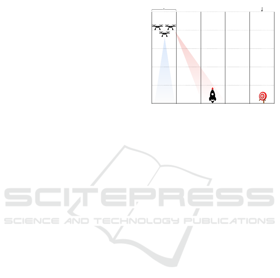
on DARTSim (Moreno et al., 2019). Fig. 1 pro-
vides an overview of a team of UAVs flying a pre-
determined path in a hostile environment, detect-
ing targets while avoiding threats. The path is di-
vided into equal segments, and sensors report detec-
tions of targets or threats. UAVs use forward-looking
and downward-looking sensors to detect targets and
threats, balancing detection with the risk of destruc-
tion. UAVs can fly at different altitudes and in loose
or tight formations. Altitude and formation affect tar-
get detection (e.g., tight formation increases sensor
overlap, reducing detection) and the likelihood of be-
ing shot down. UAVs can use electronic countermea-
sures (ECM) to lower the risk of destruction, but this
also reduces target detection. Different trade-offs al-
low UAVs to perform missions like surveillance (pri-
oritizing survival), attack (rapid target detection), or
a balance of both. Runtime adaptations between mis-
sion types must be possible to meet changing user re-
quirements.
We also need to determine how adaptation actions
impact system performance in these missions. We
will use the following metrics to evaluate different
simulation runs:
1. Average Destruction Fraction (ADF): The ADF is
the ratio of UAV destruction instances to total simula-
Altitude levelRoute segment
UAVs
Downward-
looking
sensors
Farward-
looking
sensors
Threat Target
Figure 1: Overview of the UAV model.
tions conducted.
2. Average Number of Targets Found (ANTF): The
average number of targets found by the UAVs before
being shot down or completing the path.
3. Average Decision Time (ADT): The ADT refers to
the time taken for a strategy to complete one iteration
of its decision-making process and to implement the
selected adaptation actions.
3. Average Mission Success Factor (AMSF): The mis-
sion is successful if the UAVs detect at least half of
the targets without getting destroyed, with the suc-
cess factor measured as the ratio of successful mis-
sions (e.g., 1 out of 4 yields a success factor of 25%).
Strategies. Strategies are a model-level concept for
realizing different mission types, corresponding to
specific settings of parameters that influence UAV be-
havior. We will consider the following three param-
eters: the altitude at which the UAVs fly, the forma-
tion that they fly in, and whether ECM is used or not.
For instance, flying the UAVs at high altitudes, in a
tight formation, and with ECM turned on represents
a conservative strategy suitable for surveillance-type
missions where the long-term survival of the UAVs is
paramount. For attack-type missions, an aggressive
strategy can be used in which UAVs fly low, in loose
formation, and with ECM turned off. A balanced
strategy sits between these two extremes. More strate-
gies are possible, but our implementation currently
focuses on these three. To support runtime changes to
the mission type, our exemplar allows for strategies to
be changed at runtime.
Comparison of Our Simulation with DARTSim.
Our simulation differs significantly from the initial
implementation of DARTSim (Moreno et al., 2019).
The DARTSim was a monolithic, non-distributed
MODELSWARD 2025 - 13th International Conference on Model-Based Software and Systems Engineering
54
C
++
application without cloud computing technolo-
gies. Moreover, it was not developed using MDE, nor
did it support strategies that could change at runtime.
In contrast, our version is developed using MDE tech-
niques and tools. Using our KubeRT toolchain (Ku-
beRT, 2021), the model is automatically partitioned,
containerized, and deployed on a distributed, multi-
node cloud-native environment using Google Cloud
Platform (GCP), Docker, and Kubernetes. Moreover,
our model offers additional support for adaptation
through, e.g., strategies that can be changed at run-
time, a more comprehensive monitoring infrastruc-
ture, and support runtime changes to the platform.
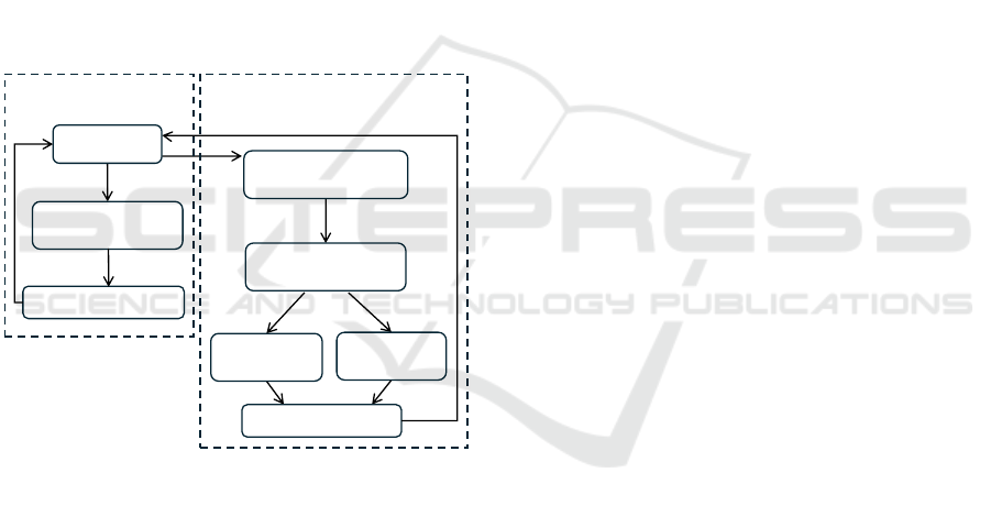
4 APPROACH AND TOOLCHAIN
Our approach for using UML-RT to develop adap-
tive cloud-based systems consists of three workflows
shown in Fig. 2.
M: Modeling
T2: Code generation
& build
T3: Execution & test
D2: Partition
& code generation
D3: Containerization
& configuration
D4L: Deploy
locally
D4C: Deploy
on cloud
C++ code
scripts
specification files
(for Docker & K8s)
GCP &
K8s setup
Workflow T
(UML-RT tooling)
Workflows DL and DC
(Our prototype tooling)
D5: Execution & test
Figure 2: The three workflows of our development ap-
proach.
Collectively, these three workflows can be used to
develop and validate a UML-RT model and create a
containerized, distributed, adaptive application from
it that executes in the cloud. All three workflows as-
sume that the system is modeled in UML-RT (Step M
in Fig. 2). Before we describe the workflows, we dis-
cuss the common step M.
4.1 Modeling (Step M)
Existing tooling can be used to develop the UML-RT
model. Development can follow standard practices
by, e.g., using iterative, incremental development in
which some base functionality is developed first fol-
lowed by support for more complex behaviors.
Support for model-level adaptation can be inte-
grated even in the very early stages of development.
As mentioned, UML-RT contains some features that
help. However, adaptation requires monitoring, as
well as the use of the collected runtime information
for effective adaptation. To facilitate this, our pro-
totype enriches the UML-RT modeling environment
with the following elements.
4.1.1 Adaptation Manager
We assume that all adaptation is triggered and over-
seen by a single capsule in the model: the Adaptation
Manager (AM). It collects relevant runtime informa-
tion, determines when the collected information indi-
cates the need for an adaptation, selects and enacts the
appropriate dynamic adaptation action (e.g., changing
parameter settings, replacing a capsule by another, or
creating a new connector). In a sense, the AM thus
concentrates much of the functionality of the MAPE-
K reference architecture (Weyns, 2020) into a single
component. To facilitate the development of a suit-
able AM, our approach includes a collection of AM
templates which can be customized as appropriate.
4.1.2 Runtime Monitoring Infrastructure
We distinguish between internal and external runtime
information. Internal runtime information is available
and collected on the model-level and includes, e.g.,
the time that a model component requires to respond
to a request (called end-to-end delay), the number of
messages exchanged in a certain time interval, or the
average size of the pay-load of certain messages. In
contrast, external runtime information is collected by
the computing platform and includes the availability
and utilization of different platform resources such as
computing nodes, memory, and CPU. The runtime
monitoring infrastructure facilitates the collection of
both internal and external runtime information.
Monitor Library. To collect internal information,
the user can choose from a library of monitors, i.e.,
a collection of customizable capsules, each of which
collects a particular kind of information. For instance,
the end-to-end delay monitor is a UML-RT capsule
that measures the time between the receipt of an in-
coming request at a capsule and the sending of the
corresponding outgoing response. It achieves this by
1) starting a timer whenever a specific message (i.e.,
the request) arrives on a specific port of a specific
component, 2) stopping the timer when the corre-
sponding response message is sent out by the com-
ponent, 3) logging the elapsed time, and 4) making
Towards the Model-Driven Development of Adaptive Cloud Applications by Leveraging UML-RT and Container Orchestration
55

Figure 3: Runtime view of deployed adaptive system.
it available to the Adaptation Manager should it ex-
ceed a certain threshold. Similarly, the message-count
monitor can be used to count the number of messages
exchanged over a specific connector within a certain
time window and alert the AM when that number ex-
ceeds some threshold. The capsule diagram in Fig. 7
shows three different monitors (i.e., delay, through-
put, and data size), the AM, and their connectors in
our UAV model.
Monitor Integration via Model Transformation.
To use a specific monitor, the user can use a model
transformation which integrates the chosen model at a
specific location and integrates it into the model as ap-
propriate. For instance, to integrate an end-to-end de-
lay monitor, the transformation takes a specification
of the request and response messages and the compo-
nent and port involved as inputs and creates the cor-
responding monitoring capsule (with, e.g., attributes
to store start and end times and their differences) and
integrates it appropriately into the existing model.
K8s Integration. For workflows DL and DC, i.e.,
for deployments on K8s clusters, K8s Metrics Server
can be used to supply the Adaptation Manager with
external runtime information such as the utilization
of different platform resources via a TCP/IP connec-
tion. Also, the AM can issue platform-level adapta-
tion commands via a connection to the K8s control
plane. Both are shown in the runtime view in Fig. 3.
E.g., the integration allows the AM in our UAV ex-
emplar to detect and correct situations in which the
platform is under- or over-utilized. Since T workflow
does not execute the application on a K8s cluster, the
use of the K8s integration is not useful there.
4.1.3 User Interaction
To allow the user to interact with the model at run-
time, the adaptation manager can receive input from
the user. For instance, in the UAV exemplar, the user
can change the mission type at runtime via a GUI.
4.2 Workflow T
The T (threaded) workflow consists of the Steps M,
T2, and T3. It uses existing tooling to generate code
from the model, build it, and validate it with respect
to, e.g., some base functionality or its adaptation ca-
pabilities.
4.2.1 Using Multi-Threading
By assigning capsules to different threads (via a trans-
formation configuration), multi-threading can be used
to develop applications that are inherently concur-
rent (e.g., applications with a need for independently
executing components for, e.g., data collection) and
to give the application the concurrency that the fi-
nal distributed application is expected to have. The
actor model eliminates the need for classical con-
MODELSWARD 2025 - 13th International Conference on Model-Based Software and Systems Engineering
56
currency control constructs (e.g., semaphores, mon-
itors, etc), but care must still be taken to ensure that
state machines receive their incoming messages when
they ‘expect them’, i.e., when they are ready to han-
dle them. A model executing correctly as a single-
threaded application may fail when multi-threading is
introduced (Posse and Dingel, 2016).
Similarly, while threads, processes, and containers
have some commonalities (i.e., all are independently
executing units of computation), there are also impor-
tant differences that a modeler needs to keep in mind
because they limit the value of any validation of the
multi-threaded code. For instance, message delivery
in multi-threaded applications is typically consider-
ably faster than in distributed, cloud-based applica-
tions. Similarly, message loss or reordering is less
likely. As a result, even a model that has been thor-
oughly tested as a multi-threaded application (follow-
ing workflow MT) may still contain bugs that only
manifest themselves when the model is executed on
a K8s cluster with specific resource constraints. So,
while the validation afforded by the MT flow is use-
ful, it does not obviate the need for more validation
when the model is executed as a distributed applica-
tion using workflows DL and DC.
4.3 Workflows DL and DC
The workflow DL (distributed, local) (Steps M, D2,
D3, D4L, and D5) deploys the application on a lo-
cal K8s cluster. In workflow DC (distributed, cloud)
the application is deployed in the cloud by replacing
Step D4L by Step D4C.
4.3.1 Partition & Code Generation (Step D2)
This step prepares the cloud deployment by partition-
ing the model, adding support for automatic failure
recovery, and generating the necessary code, scripts,
and configuration files. Our prototype implements
this step using KubeRT (KubeRT, 2021), which serves
as an automatic partitioning and code and script gen-
eration framework for UML-RT models.
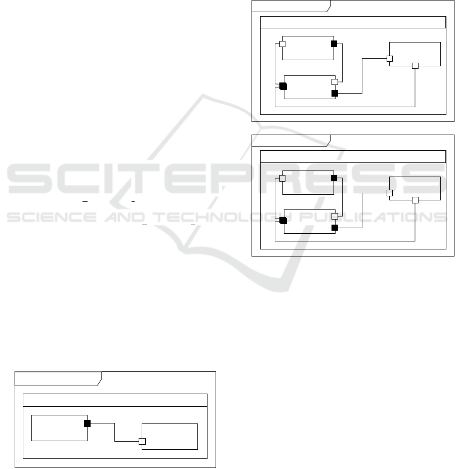
Pinger Ponger
Top
ping
pong
ponger: Ponger
pinger: Pinger
M
'
pinger ponger
Figure 4: Sample UML-RT model.
Partitioning. In the model created in Step M, cap-
sules represent separately executable and deployable
units that can run on different nodes in the cloud en-
vironment and yet still communicate with each other
as indicated by the connectors. Partitioning achieves
this separate deployability by turning every capsule
in the model into its own separate, standalone model
M
′ ′
such that existing code generation can be used to
generate separately executable code for each capsule
while fully preserving communication abilities to the
components it is connected to.
Top.pinger[0]
ping
p1
controller:
ModelController
pong
c1
c2[2]
p3
p2
pongerProxy:
PongerProxy
pinger: Pinger
M
''
pinger
(a)
Top
(b)
Top.ponger[0]
ping
p1
controller:
ModelController
pong
c1
c2[2]
p3
p2
ponger: Ponger
pingerProxy:
PingerProxy
M
''
ponger
Top
Figure 5: Partitioned version of sample model in Figure 4.
To preserve communication ability we use proxy
capsules. Consider, for example, the model in Fig. 4
containing two capsules pinger and ponger with a
single connector. The partitioning process will pro-
duce two models, one for pinger (Fig. 5 (a)) and one
for ponger (Fig. 5 (b)). In the model for pinger,
the component it was connected to in the original
model (ponger) is replaced by a proxy component
(pongerProxy). Similarly for the model created for
ponger. Messages from pinger originally sent to
ponger will now be sent to pongerProxy which will
forward them (via remote communication) to the
model that now represents ponger. Once they arrive at
the model, the proxy representing pinger will forward
it to the ponger component. Similarly for messages
sent from ponger.
In our prototype, KubeRT realizes the partitioning
with the help of model transformations. The proxy
Towards the Model-Driven Development of Adaptive Cloud Applications by Leveraging UML-RT and Container Orchestration
57

capsules use TCP by default to establish connections
and messages are encoded in JSON format. More-
over, KubeRT is extensible and supports additional
network protocols and data formats.
Support for Failure Recovery. As part of the par-
titioning process, the model is also updated such
that the resulting application can take advantage of
the failure recovery capabilities that containerization
management frameworks offer. For instance, Kuber-
netes can automatically restart failed containers. Our
approach allows the modeled application to take ad-
vantage of this capability. Concretely, it realizes a
failure recovery process for individual capsules that
guarantees that every message will be delivered and
processed by its intended recipient assuming proper
operating conditions are eventually restored.
To achieve this, a controller is added to every stan-
dalone model M
′′
created by the partitioning (Fig. 5).
The controller is placed between the capsules and
all proxies allowing it to intercept all messages ex-
changed between the capsules and the proxies. More-
over, the capsule is modified so that it can, upon re-
quest from the controller, serialize its current runtime
state and send it to the controller (checkpointing), and
recover from failure by restarting in a state sent to it
by the controller (state recovery).
Finally, an acknowledgment and retransmission
protocol is added to the capsule so that it automat-
ically retransmits messages that remain unacknowl-
edged due to a failure. Before forwarding a mes-
sage to the capsule, the controller obtains and saves
the current runtime state of the capsule. Upon restart
from a failure, the controller restarts the capsule with
the previously stored state.
Code, Script & Specification Generation. Ku-
beRT uses the Papyrus-RT code generator to generate
C
++
code for each partitioned model along with the
associated specification files and scripts for Docker,
K8s, and Gradle. I.e., for each generated model M
′′
,
several artifacts are created including the following:
1) Docker File: A Docker file to build a container
image that executes the code generated from model
M
′ ′
. All images extend the same base image. The
base image includes the toolchain required to build
and execute UML-RT models.
2) K8s Deployment Specification File: A YAML file
that requests the deployment of a K8s pod running the
image. The deployment YAML file is generated with
its default deployment configurations, which can be
modified as needed.
3) K8s Service Specification File: A YAML file that
exposes the TCP port of every proxy capsule in M
′ ′
.
4) Model UML Files: The UML files for each compo-
nent from which the C
++
code is generated.
5) Gradle Build Script: Covers the entire deployment
process by defining the tasks and their dependencies
needed to deploy the model on the K8s cluster.
4.3.2 Containerization & Configuration (D3)
The code and its dependencies, including Docker
files, specifications in YAML files, and build scripts
are bundled together to generate Docker images of
the application, which can be deployed on a local or
a remote cluster. The resulting Docker images are
then published to the container registry of the cloud
platform. K8s Metrics Server and Dashboard (Fig. 3)
are configured.
4.3.3 Local Deployment (Step D4L)
Minikube, a tool for running a K8s environment lo-
cally, is used to deploy and run the application.
4.3.4 Cloud Deployment (Step D4C)
The GCP is used to deploy the generated application
on a K8s cluster running in the cloud. GCP is config-
ured using the Google Cloud CLI (Fig. 3). Virtual
Machine (VM) instances are created in the Google
Compute Engine, which acts as the IaaS component
of GCP. The local environment is configured to inter-
act with the GCP and allows us to push, store, and
manage project images in the GCP container registry.
For remote K8s deployment, we configured the
K8s dashboard and the command line tool kubectl and
used them to manage the cluster and perform tasks
such as monitoring, scaling, pod creation/deletion,
and tracking resource usage across nodes.
4.3.5 Execution & Test (Step D5)
There are several ways to interact with the model and
the platform during execution (Fig. 3). During de-
velopment (e.g., for testing purposes), the developer
can monitor and modify the use of platform resources
using Jupyter Notebooks, kubectl, or the K8s Dash-
board. After the development, a user of the applica-
tion can use a GUI to interact with the model.
5 EVALUATION
To evaluate our work and answer the research ques-
tions (RQs) posed in Section 1, we have used our
approach and prototype to create and deploy several
cloud applications that all exhibit different kinds of
self-adaptive behavior.
MODELSWARD 2025 - 13th International Conference on Model-Based Software and Systems Engineering
58
5.1 Containerization & Deployment
(RQ1)
The initial research question (RQ1) focuses on the
ability to model, monitor, containerize, and deploy
self-adaptive cloud applications. Below, we will de-
scribe four such applications that we have developed
using our approach and prototype.
5.1.1 Word Count (WC)
The problem is to count occurrences of a specific
word in text files. Using our prototype we have cre-
ated a model in which the managing capsule dynam-
ically instantiates and invokes a counter capsule for
each file. After counting, the manager computes the
total occurrences and uses a delay monitor to track the
time taken. If this time exceeds a threshold, the man-
ager triggers a platform adaptation, redeploying the
application on a platform with more resources (i.e.,
CPU or memory). Containerization and deployment
took 78 and 11 seconds, respectively (Table 1).
5.1.2 Sieve of Eratosthenes (SoE)
The sieve application identifies prime numbers in a
given integer range. The manager dynamically cre-
ates agents, assigns each a subinterval, and combines
their results. Like word count, it uses a delay moni-
tor, triggering additional platform resources if needed.
Containerization and deployment took slightly longer
than the word count model (Table 1).
5.1.3 Parcel Router (PR)
A parcel router is an automated system that directs
tagged parcels through chutes and switchers to reach
their destination bins, with switchers adjusting door
orientations based on parcel tags. The system is time-
sensitive, and blockages can occur due to varying
transit times through the chutes (Magee and Kramer,
2006). Using our approach and tooling we have cre-
ated a self-adaptive, cloud-based simulation of a par-
cel router.
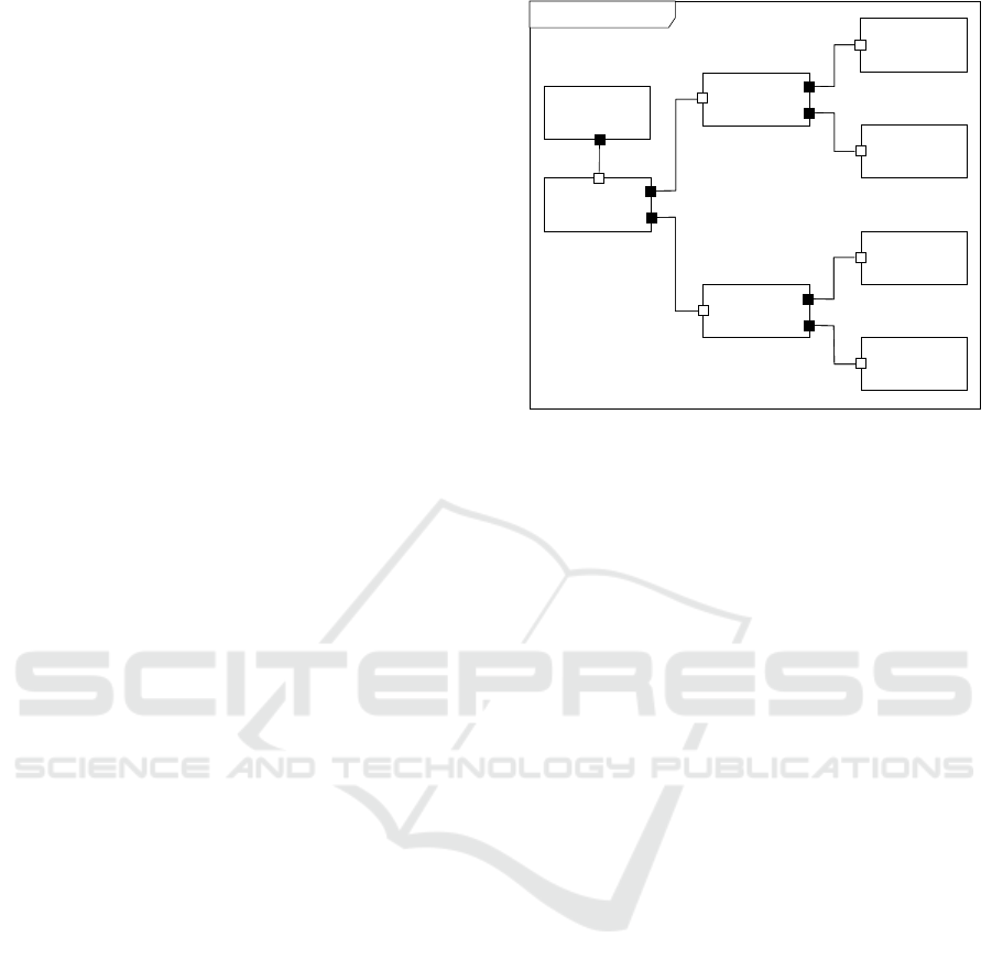
As shown in Fig. 6, the model includes a gen cap-
sule for generating parcels and three stages for direct-
ing parcels to four bins, divided into chutes, switch-
ers, and sensors. A sensor reads each parcel’s tag, and
the switcher directs it to the correct bin or next stage.
The model has 21 components, excluding monitors.
Delay and throughput monitors track parcel delivery
times and count parcels delivered within intervals.
Unlike previous models, parcel router monitors can
be dynamically enabled or disabled by the manager
using UML-RT’s plug-in capsule mechanism. Plat-
Parcel Router
top: Stage
gen: Gen
left: Stage
b0: Bin
b1
b1: Bin
b2
right: Stage
r1
b2: Bin
b3
b3: Bin
t2
t3
l1
r2
r3
l2
l3
b4
top: Stage
g1
gen: Gen
left: Stage
b1: Bin
b2: Bin
right: Stage
r1
b3: Bin
b4: Bin
l1
l2
l3
t1
Figure 6: Parcel router (adaptation manager and monitors
are not shown).
form adaptation enhances runtime performance, with
containerization and deployment times of 342 and 24
seconds, respectively (Table 1).
5.1.4 UAV Exemplar
The UAV exemplar emulates a group of UAVs navi-
gating an environment, identifying targets, and evad-
ing threats. Using our approach and tooling, we cre-
ated a cloud-based simulation of UAVs with self-
adaptation capabilities.
As shown in Fig. 7, the DartMain component han-
dles simulator functions like environment initializa-
tion and sensor interactions. The AdaptationMgr as-
sesses strategy changes and instructs the model to ad-
just parameters (as discussed in Section 3) for im-
proved target detection and threat avoidance. This
iterative process continues until the simulation con-
cludes or the UAVs are destroyed. Monitors track
end-to-end delay, data size, and message counts,
while the Metrics component collects system metrics
(i.e., CPU and memory usage), from the K8s metrics
server, and the Log component manages logs. The
simulation is initialized with inputs such as map size,
number of UAVs, and altitude. The AdaptationMgr
dispatches adaptation commands to DartMain, which
executes them and reports back upon completion. The
Delay monitor measures the command response time;
if this time exceeds a threshold, AdaptationMgr initi-
ates platform adaptation by requesting additional re-
sources.
The generated deployment YAML file defines and
configures the Kubernetes deployment on a cluster. It
includes the apiVersion and kind fields for resource
type, a metadata section with the deployment’s name,
namespace, and labels, and a spec section specify-
Towards the Model-Driven Development of Adaptive Cloud Applications by Leveraging UML-RT and Container Orchestration
59

UAVs Simulation
delay:
Delay
g1
dartMain:
DartMain
datasize:
DataSize
g1
throughput:
Throughput
metrics:
Metrics
g1
adaptationmgr:
AdaptationMgr
p7
p8
p9
p10
p3
p4
a2
p5
p6
p1
log:
Log
a1
p2
t1
t2
t3
t4
t5
t6
t7
t8
t9
t10
t12
t11
Figure 7: Model of the UAV simulation after integration of the monitors.
ing pod replicas, selectors, and a pod template. The
pod template, in turn, includes metadata with labels,
specifications regarding volumes, a list of containers,
their respective images, volume mounts, and resource
requirements for CPU and memory. These specifi-
cations allow fine-tuning the resources allocated to
pods within the Kubernetes cluster. The model for
UAV simulation is significantly larger than the other
models discussed in this section (about 50 compo-
nents). As a result, containerization and deployment
also took significantly longer (Table 1).
Table 1: Containerization and deployment time.
Model Containerization Deployment
(sec) (sec)
WC 78 11
SoE 96 12
PR 342 24
UAV 512 54
The results in Table 1 demonstrate the container-
ization and deployment of the models, which is dom-
inated by the containerization time. The containeriza-
tion time typically increases linearly with the num-
ber of components due to the need to create container
images and generate code for each component. In
contrast, the deployment time remains minimally af-
fected, as it involves executing non-intensive tasks
for the deployment process. We note that our pro-
totype focuses on demonstrating feasibility and that
containerization and deployment times could proba-
bly be reduced through suitable optimization.
The answer to RQ1 is that with our automatic
containerization and deployment toolchain, it is
possible to partition the monolithic model into in-
dividual components and generate related config-
uration files and code, which can be containerized
and deployed, allowing the model-driven devel-
opment of containerized applications deployable
on local and cloud-native infrastructure.
5.2 Failure Recovery (RQ2)
To evaluate the effectiveness of the automatic failure
recovery capability added to the model in Step D2 of
the approach, we used the parcel router model. While
executing the model on a Kubernetes cluster, an exter-
nal Python script was used to induce failures. At ran-
dom times, the script selects a random subset of the
21 components and injects a command into their con-
tainers that causes a kernel panic. In total, 67 failures
were induced, each with an average of 8 components.
During the execution, the maximum number of si-
multaneously failed components hit 21. Nonetheless,
our failure recovery mechanism managed to recover
from every failure, and all the parcels were eventually
routed to their correct destination. Table 2 shows the
time taken to recover from failures and resume the ex-
ecution for various failed components. The majority
of time is taken by the Kubernetes engine to restart
the failed container while the remaining time is taken
by the state and message recovery process.
Table 2: Performance of the failure recovery process.
No. of Failed Restart Time Recovery Time
Components (sec) (sec)
1 3 1
5 6 4
10 14 10
15 27 13
20 33 17
As described in Section 4.3.1, our approach re-
quires serializing and saving the state of a capsule
whenever it has processed a message. Our exper-
iments showed that, on average, this checkpointing
process imposed a 3.2% overhead on the message
processing time, which can be a concern for appli-
cations with a high message frequency. The overhead
can further increase for components with a large state.
Improvements could be made by, e.g., incrementally
saving the state by computing deltas.
MODELSWARD 2025 - 13th International Conference on Model-Based Software and Systems Engineering
60
The answer to RQ2 is that, building on Ku-
bernetes’ failure recovery capabilities, relatively
strong fault tolerance guarantees can be offered
on the model-level and implemented through
mechanisms (checkpointing, state recovery, and
retransmission) that are added automatically
through model transformation and remain trans-
parent to the user.
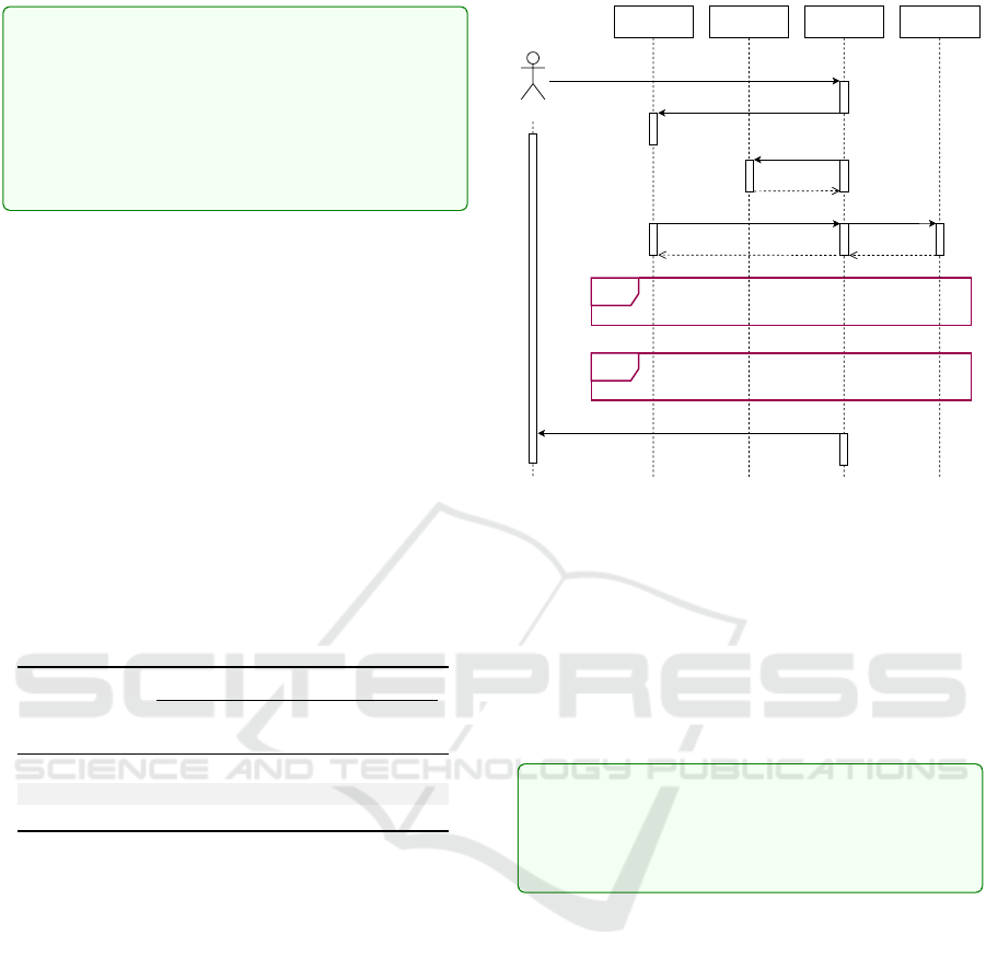
5.3 Model-Level Adaptation (RQ3a)
To evaluate the ability of the approach and prototype
to adapt to changing user requirements using adap-
tation on the model-level, we use our UAV exem-
plar and allow users to change the type of the mis-
sion (surveillance, attack, or balanced) at runtime. As
shown in Fig. 8, this user input is sent to the Adap-
tation Manager and possibly causes it to change the
strategy that governs the choice of the parameters that
influence the behavior of the UAVs. The manager
then (re-)initializes the K8s metrics server used to
collect platform-level metrics (i.e., external runtime
information) and then runs the simulation using the
chosen strategy.
Table 3: Effectiveness of strategies.
Metric
Strategy ADF ANTF ADT AMSF
(%) (#) (ms) (%)
Conservative 9 0.7 19559 0.5
Aggressive 100 1.1 13247 0
Balanced 18 2.5 14691 20.7
Sub-scenarios (like Run strategy and Results col-
lection) include the monitors, which are not shown in
Fig. 8. During the simulation, internal and external
runtime information is sent to the Adaptation Man-
ager and the Log capsule from the delay, throughput,
data size monitors, and the metrics server (Fig. 7).
Upon completion of the simulation, results are col-
lected and passed to the user with the system log.
To evaluate the effectiveness of the strategy selec-
tion and change process, we use the metrics described
in Section 3 to assess different missions using differ-
ent strategies. The results are shown in Table 3. As
we can see, the average destruction fraction (ADF) is
lowest for the conservative strategy, highest for the
aggressive strategy, and moderate for the balanced
strategy. The balanced strategy found the highest av-
erage number of targets (ANTF), followed by the ag-
gressive strategy, and the conservative strategy found
the least. The average decision time (ADT) is lowest
for aggressive strategy, and highest for the conserva-
tive strategy. The balanced strategy has the highest
Figure 8: Sequence diagram of UAV simulation.
average mission success factor (AMSF), followed by
the conservative strategy, while the aggressive strat-
egy has the lowest. We observe that the strategies
not only impact UAV performance but also cause mis-
sions to support the mission type chosen by the user,
i.e., the user-level requirements. The strategy selec-
tion process takes place at runtime and thus allows the
simulation to adapt effectively to dynamic changes to
user-level requirements.
The response to RQ3a is that our approach and
prototype tool can support the model-driven de-
velopment of cloud applications that perform
model-level adaptation to effectively respond to
application requirements that change at runtime.
5.4 Platform-Level Adaptation (RQ3b)
To evaluate the ability of the approach and prototype
to support adaptation to changing user requirements
via changes to the computing environment we again
use the UAV exemplar. We define two types of plat-
forms: minimal and maximal. A minimal platform
offers only modest resources but would be less expen-
sive. Concretely, a minimal platform offers 100 mil-
liCPU (units of virtual CPU in K8s), 128 MebiBytes
(units of virtual memory in K8s), and one node. E.g.,
the K8s deployment configuration file would run the
UAV simulation on a minimal platform. Conversely,
a maximal platform offers more resources but would
also be more expensive. Concretely, it offers 500 mil-
liCPU, 512 MebiBytes, and a cluster of three nodes.
We enable the Adaptation Manager to dynami-
cally change the deployment configuration and re-
Towards the Model-Driven Development of Adaptive Cloud Applications by Leveraging UML-RT and Container Orchestration
61

quest a different platform if the runtime information
it has access to suggests that the current platform is
not suitable. For instance, a large end-to-end delay
between the manager issuing a command to the simu-
lation (i.e., the DartMain component) and the response
might suggest that the application is under-resourced
and would prompt the manager to switch from a min-
imal to a maximal platform.
We then assess the effect of the platform change
on the mission metrics, specifically the impact of re-
placing a minimal platform with a maximal platform.
In the context of the conservative and balanced strate-
gies, the availability of additional resources results in
≈ 50% improvement in the average destruction frac-
tion (ADF). For various strategies, the average num-
ber of targets found (ANTF) also increased by ≈ 50%.
Additionally, the average decision time (ADT) im-
proved by ≈ 15% across different strategies when uti-
lizing higher-resource platforms. The average mis-
sion success factor (AMSF) shows an approximate
twofold improvement for balanced and conservative
strategies on higher-resource platforms.
In other words, we see evidence that the availabil-
ity of more resources does indeed allow the applica-
tion to satisfy the user requirements (i.e., the chosen
mission type) to a higher degree. Intuitively, this is
because relevant parts of the application become more
responsive and can process inputs or respond to re-
quests or change runtime information such as sensor
input with less delay, allowing the application to, e.g.,
detect a target or threat where previously it did not.
In response to RQ3b, we conclude that our ap-
proach can support the model-driven development
of cloud applications that use dynamic platform
adaptation effectively to respond to changing user
requirements.
6 THREATS TO VALIDITY
Threats to internal validity stem from the possibility
of a bug in our data collection and analysis. For ex-
ample, some of our data used in Section 5 (Tables 1,
2 and 3) may be incorrect, leading to adaptations that
do not have the described effect on the application’s
behavior. We use careful inspection and testing of the
data and code that we collect and analyze to mitigate
this threat.
External threats may undermine the generalizabil-
ity of the results. Firstly, we recognize that additional
case studies are necessary to assess the broader appli-
cability and efficacy of our approach, especially for
industrial-sized cloud-based adaptive systems. Sec-
ondly, our approach requires users to have expertise in
UML-RT, and without sufficient knowledge, they may
be unable to fully leverage its benefits. Compared to
the real-time embedded systems domain, knowledge
of UML-RT in cloud applications is probably limited,
posing a significant impediment to the broader adop-
tion of our approach for cloud-based applications.
7 CONCLUSION
As answers to our RQs, our work contributes: 1) a
UML-RT-based approach and toolchain for the MDE
of cloud-based, containerized, adaptive applications
that leverage existing UML-RT tooling and the capa-
bilities of container orchestration platforms such as
K8s, and 2) an exemplar for the evaluation of our
and, potentially, other work on this topic. The ben-
efits of our approach are that developers can express
the system in a proven, mature language (UML-RT)
with strong foundations (Posse and Dingel, 2016) and
built-in support for dynamic change to the structure
and behavior of the model (Kahani et al., 2017). They
can also use existing tool support to generate single-
or multi-threaded code from the model and use it
to evaluate prototypes, without the need for poten-
tially costly and time-consuming cloud deployment
and execution. Then, when appropriate, developers
can, with only small changes to the model, use our
toolchain to generate containerized code and execute
it on a K8s cluster running locally or in the cloud.
Our ongoing and future work aims to address the
two main shortcomings of our approach and its cur-
rent prototype implementation:
Further Leveraging the Capabilities of Container
Management Platforms: Some of the orchestration
mechanisms for, e.g., automatic scaling assume state-
less applications, complicating their use for stateful
applications. Our approach shows how this challenge
can be dealt with in the context of failure recovery
by enabling components to recover the previous state.
However, it is unclear to what extent existing plat-
form support for automatic scaling of stateful appli-
cations (such as StatefulSets in Kubernetes) can be
used to extend our approach and allow the platform to
dynamically replicate certain components in response
to increased demand.
Refine Adaptation Support: A related avenue for fu-
ture work is support for more complex, tradeoff-
aware decision-making by, e.g., integrating platform
costs and allowing the user to specify an optimization
function, i.e., how different performance and cost as-
pects should be weighed. A considerable amount of
work on this topic already exists, but the realization
in the context of our approach needs to be explored.
MODELSWARD 2025 - 13th International Conference on Model-Based Software and Systems Engineering
62

REFERENCES
Agha, G. A. (1985). Actors: A model of concurrent compu-
tation in distributed systems. Technical report, MIT,
Cambridge Artificial Intelligence Lab.
Alfonso, I., Garc
´
es, K., Castro, H., and Cabot, J. (2021).
Modeling self-adaptative IoT architectures. In Inter-
national Conference on Model Driven Engineering
Languages and Systems Companion. IEEE.
Bencomo, N., Goetz, S., and Song, H. (2019). Mod-
els@run.time: A guided tour of the state of the art and
research challenges. Software and Systems Modeling,
18:3049–3082.
Beyer, B., Jones, C., Murphy, N., and Petoff, J. (2016). Site
Reliability Engineering: How Google Runs Produc-
tion Systems. O’Reilly.
Bradbury, J. S., Cordy, J. R., Dingel, J., and Wermelinger,
M. (2004). A survey of self-management in dynamic
software architecture specifications. In Proceedings
of the 1st ACM SIGSOFT Workshop on Self-managed
Systems, pages 28–33.
Burns, B., Beda, J., and Hightower, K. (2019). Kubernetes:
Up and Running: Dive into the Future of Infrastruc-
ture. O’Reilly Media.
Butting, A., Heim, R., Kautz, O., Ringert, J. O., Rumpe,
B., and Wortmann, A. (2017). A classification of dy-
namic reconfiguration in component and connector ar-
chitecture description languages. In 4th Intl. Work-
shop on Interplay of Model-Driven and Component-
Based Software Engineering (ModComp’17).
Casalicchio, E. (2019). Container orchestration: A sur-
vey. In Systems Modeling: Methodologies and Tools,
pages 221–235. Springer.
Cesarini, F. and Thompson, S. (2009). Erlang program-
ming: A concurrent approach to software develop-
ment. “O’Reilly Media, Inc.”.
Elkhodary, A., Esfahani, N., and Malek, S. (2010). FU-
SION: A framework for engineering self-tuning self-
adaptive software systems. In 18th ACM SIGSOFT
International Symposium on Foundations of Software
Engineering, pages 7–16.
Gao, Q., Brown, L., and Capretz, L. F. (2004). Extending
UML-RT for Control System Modelling. American
Journal of Applied Sciences, 1(4):338–347.
Garlan, D., Cheng, S.-W., Huang, A.-C., Schmerl, B., and
Steenkiste, P. (2004). Rainbow: Architecture-based
self-adaptation with reusable infrastructure. Com-
puter, 37(10):46–54.
Herzberg, D. (1999). UML-RT as a candidate for modeling
embedded real-time systems in the telecommunica-
tion domain. In International Conference on the Uni-
fied Modeling Language, pages 330–338. Springer.
Kahani, N., Hili, N., Cordy, J. R., and Dingel, J. (2017).
Evaluation of UML-RT and Papyrus-RT for modelling
self-adaptive systems. In 2017 IEEE/ACM 9th Inter-
national Workshop on Modelling in Software Engi-
neering, pages 12–18. IEEE.
Kramer, J. and Magee, J. (2007). Self-managed systems:
An architectural challenge. In Future of Software En-
gineering, pages 259–268. IEEE.
Krupitzer, C., Roth, F. M., VanSyckel, S., Schiele, G.,
and Becker, C. (2015). A survey on engineering ap-
proaches for self-adaptive systems. Pervasive and Mo-
bile Computing, 17:184–206.
KubeRT (2021). KubeRT - Automated partitioning and
deployment of UML-RT models. https://github.com/
qumase/kubert. Accessed: 2024-09-25.
Leue, S., Stefanescu, A., and Wei, W. (2008). An AsmL se-
mantics for dynamic structures and run time schedu-
lability in UML-RT. In Proceedings of Objects, Com-
ponents, Models and Patterns, pages 238–257.
Magee, J. and Kramer, J. (2006). Concurrency: State Mod-
els & Java Programs (2nd Ed.). Wiley.
Moreno, G., Kinneer, C., Pandey, A., and Garlan, D.
(2019). DARTSim: An exemplar for evaluation and
comparison of self-adaptation approaches for smart
cyber-physical systems. In 14th International Sympo-
sium on Software Engineering for Adaptive and Self-
Managing Systems (SEAMS), pages 181–187. IEEE.
Posse, E. and Dingel, J. (2016). An executable formal se-
mantics for UML-RT. Software & Systems Modeling,
15(1):179–217.
Pueschel, G., Goetz, S., Wilke, C., and Assmann, U.
(2013). Towards systematic model-based testing of
self-adaptive software. In 5th Intl. Conference on
Adaptive and Self-Adaptive Systems and Applications.
Roestenburg, R., Williams, R., and Bakker, R. (2016). Akka
in action. Simon and Schuster.
Salehie, M. and Tahvildari, L. (2009). Self-adaptive soft-
ware: Landscape and research challenges. ACM
Transactions on Autonomous and Adaptive Systems
(TAAS), 4(2):1–42.
Selic, B. (2006). UML 2: A model-driven development
tool. IBM Systems Journal, 45(3):607–620.
Selic, B., Gullekson, G., McGee, J., and Engelberg, I.
(1992). ROOM: An object-oriented methodology for
developing real-time systems. In 5th International
Workshop on Computer-Aided Software Engineering.
Spyker, A. (2020). Disenchantment: Netflix titus, its feisty
team, and daemons. In InfoQ. www.infoq.com/
presentations/netflix-titus-2018.
Tajalli, H., Garcia, J., Edwards, G., and Medvidovic, N.
(2010). PLASMA: A plan-based layered architecture
for software model-driven adaptation. In Proceedings
of the 25th IEEE/ACM International Conference on
Automated Software Engineering, pages 467–476.
Vogel, T. and Giese, H. (2014). Model-driven engineer-
ing of self-adaptive software with EUREMA. ACM
Transactions on Autonomous and Adaptive Systems
(TAAS), 8(4):1–33.
von der Beeck, M. (2006). A formal semantics of UML-
RT. In Intl. Conference on Model Driven Engineering
Languages and Systems, pages 768–782. Springer.
Weyns, D. (2020). An Introduction to Self-adaptive Sys-
tems: A Contemporary Software Engineering Per-
spective. Wiley.
Weyns, D. et al. (2023). Self-adaptation in industry: A sur-
vey. ACM Transactions on Autonomous and Adaptive
Systems (TAAS).
Towards the Model-Driven Development of Adaptive Cloud Applications by Leveraging UML-RT and Container Orchestration
63
