
Development of Optrodes and Instrumentation
for Wireless Optogenetic Application
H. E. Oshiro
1,2 a
, R. A. P. Andrade
2 b
, J. N. S. Junior
1 c
, M. Luppe
1 d
,
E. Colombari
3 e
, M. C. Dias
4 f
and J. P. Carmo
1 g
1
Group of Metamaterials Microwaves and Optics (GMeta), Department of Electrical Engineering (SEL), University of São
Paulo (USP), Avenida Trabalhador São-Carlense, Nr. 400, São Carlos 13566-590, SP, Brazil
2
brain4care, Avenida Bruno Ruggiero Filho, 971 - Parque Santa Felícia Jardim, São Carlos, SP, 13562-420, Brazil
3
Department of Physiology and Pathology, Faculty of Odonthology, São Paulo State University (UNESP), Rua Humaitá,
Nr. 1680, Araraquara 14801-385, SP, Brazil
4
Faculty of Medicine, University of Porto, Alameda Hernani Monteiro, piso 8, Unidade Cuidados Neurocriticos,
rodrigoapandrade@gmail.com, eduardo.colombari@unesp.br, mcdias@med.up.pt
Keywords: Optrode, Optogenetics, Biopotentials.
Abstract: Optogenetics combines optical and genetic techniques to control and monitor neuronal activities. Recent
efforts focus on developing portable and wireless electronics for optical activation and biopotential
acquisition. These advancements aim to offer greater mobility and freedom for studying animals, contrasting
with the large equipment commonly found in laboratories for laser activation, signal amplification, and data
acquisition. This study presents the development of a wireless optrode system for optogenetics, integrating
optical stimulation and biopotential acquisition in a compact, portable format.
1 INTRODUCTION
Genetic engineering techniques are used to allow
neuronal populations to produce light-sensitive
proteins. These proteins can be stimulated or
inhibited by specific light patterns and wavelengths.
Deisseroth et al. (2006) defined optogenetics as a
technology that “combines genetic targeting of
specific neurons or proteins with optical technology
for imaging or control of the targets within intact,
living neural circuits”. To validate neuronal responses
to light stimulation, electrodes and techniques such as
patch-clamp electrophysiology can be employed,
allowing precise measurements of intracellular and
synaptic activity evoked by optical stimuli, as
demonstrated by Boyden et al. (2005).
a
https://orcid.org/0000-0003-0370-4700
b
https://orcid.org/0000-0002-7248-4636
c
https://orcid.org/0000-0002-1975-2267
d
https://orcid.org/0000-0001-7419-2154
e
https://orcid.org/0000-0002-1395-4036
f
https://orcid.org/0000-0003-0340-9808
g
https://orcid.org/0000-0001-7955-7503
In the current context, optogenetics applications
are generally carried out in laboratories equipped with
large optical equipment and instruments for reading
signals. Compact systems are being developed to
address limitations such as the need for wiring and
dependence on multiple pieces of equipment (light
emission controllers, acquisition hardware and
independent implantable parts), promoting greater
mobility in animal studies and allowing their free
behavior. The next chapters will address the
development of an optical stimulation system that
integrates with a biosignal acquisition system and
features an optrode module for use with an embedded
biosignal acquisition and optical stimulus control
system.
Oshiro, H. E., Andrade, R. A. P., S. Junior, J. N., Luppe, M., Colombari, E., Dias, M. C. and Carmo, J. P.
Development of Optrodes and Instrumentation for Wireless Optogenetic Application.
DOI: 10.5220/0013148100003911
Paper published under CC license (CC BY-NC-ND 4.0)
In Proceedings of the 18th International Joint Conference on Biomedical Engineering Systems and Technologies (BIOSTEC 2025) - Volume 1, pages 1073-1079
ISBN: 978-989-758-731-3; ISSN: 2184-4305
Proceedings Copyright © 2025 by SCITEPRESS – Science and Technology Publications, Lda.
1073

2 OPSINS
Opsins are essential tools in optogenetics, allowing
neuronal circuits to be stimulated or inhibited by
light. “Opsins are membrane-bound proteins that are
activated by light, which results in activation
(depolarization), inhibition (hyperpolarization), or
modulation of the intracellular signaling cascade”
(Guru et al., 2015). Opsins function as ion channels
or pumps that are activated by specific wavelengths
of light. “Upon activation by light, these channels and
pumps respond by opening or closing, which
conducts the flow of ions into or out of the cell”
(Addgene, n.d.). Three commonly used opsins
include:
(1) Channelrhodopsins: channel-type opsins
that allow rapid depolarization of neurons through
direct stimulation of ion channels when exposed to
light (Addgene, n.d.). Channelrhodopsin-2 (CHR2) is
activated by light with wavelengths in the range of
400nm to 500nm (Dufour et al., 2015).
(2) Halorhodopsins (NpHR): opsins that pump
chloride ions into the neuronal membrane, causing
cellular hyperpolarization and inhibiting neuron
activation. NpHR is activated by light with
wavelengths in the range of 550nm to 620nm
(Dufour et al., 2015).
(3) Archaerhodopsins: light-controlled opsins
that pump protons out of the neuronal membrane,
causing cellular hyperpolarization and inhibiting
neuron activation. ArchT is activated by light with
wavelengths in the range of 500nm to 600nm
(Dufour et al., 2015).
In this way, an optrode can be equipped with
different light sources to suit the use in conjunction
with the different opsins used for different studies and
purposes.
3 SYSTEM ARCHITECTURE
The optrode developed in this project was designed
for use in a wireless system for optogenetic
stimulation and signal recording. The system is
compact, battery-operated, and integrates a
microcontroller with wireless communication, along
with circuits such as an analog-to-digital converter,
auxiliary sensors, and a power management system.
The acquisition system connects to the optrode via a
board-to-board connector.
The structure of the acquisition system is
represented in Figure 1.
3.1 Optrode Module
The optrode module connects to the acquisition
board, receiving the necessary power, the
communication buses and delivering the analog
signals to the ADC (analog to digital converter) in the
other board. Its architecture is shown in Figure 2.
The board incorporates a signal filtering stage to
ensure adequate visualization of the read signals, a
temperature sensor and auxiliaries to monitor the
activity of the study animal, in addition to means of
controlling the light pattern. As optrode module
design requirements, the following items have been
listed:
(1) It must have a means of delivering light;
(2) It must have an interface with electrodes;
(3) It must provide rapid integration and
configuration with the acquisition/control system;
(4) It must provide means for optical control of
excitation patterns;
(5) It must provide the necessary energy for the
components;
(6) It must provide an adequate analog
interface;
(7) It may include additional sensors.
3.1.1 Implantable Interface
To stimulate and measure the activity of a test animal,
it is necessary to perform optical delivery and reading
of the biopotentials of interest. Signal acquisition is
generally achieved through electrodes. As the optrode
module provides signal delivery to the acquisition
board's ADC, it is possible to adapt the module to
capture signals from other sensors, such as pressure
and temperature sensors, just by modifying the
interface with the test animal and without interfering
with the main acquisition and control module.
Light delivery can be done by optical fiber, or, as
adopted in this project, by small SMD LEDs.
4 DEVELOPMENT
4.1 Light Emitter
To stimulate or inhibit neurons expressing opsins,
light at the appropriate frequency and intensity must
reach the target. Each type of opsin responds to a
specific wavelength of light, as mentioned
previously. For ChR2 photostimulation,
Chen et al. (2016) mentions pulse widths between
1ms and 15ms as typical requirements, pulse
EM4Health 2025 - Special Session on Electromagnetic waves for healthcare
1074
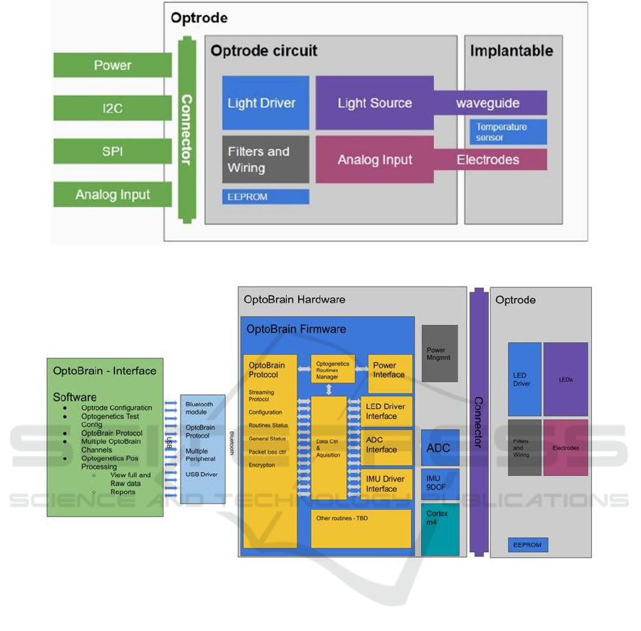
Figure 1: Optrode module architecture.
Figure 2: System architecture for optogenetics.
frequency between 1Hz and 50Hz, and an optical
power at the fiber tip of at least 32µW. A minimum
irradiance of 1mW/mm² when delivering light to
neurons via an optrode (Freitas et al., 2021).
There are three common types of light sources
used for excitation in optogenetics: arc lamps, lasers,
and LEDs. The work by Lin (2012) mentions the
following characteristics for each of the light sources:
(1) Arc lamps: provides a continuous spectrum
of wavelengths in the visible range. However,
lighting control is done via a shutter, limiting the
stimulation frequency.
(2) Lasers: provides high-intensity light that
can be coupled to an optical fiber. It usually involves
a high equipment cost and wavelengths are limited
(3) LEDs (light-emitting diodes): physically
smaller than other options and can be mounted
directly on the brain. Due to its size and current, it can
generate heat. Its intensity is typically weaker
compared to the other options.
In this project, the use of LED was chosen to meet
the need to obtain a compact and low energy
consumption system in a wearable device. To
interface the optrode module in delivering light to the
test animal, an arrow-shaped printed circuit board
with a width of 0.7mm and a pointed end was
manufactured. Figure 3 shows a photograph of a
prototype of the implantable interface, which has only
two tracks and pads for soldering the LED, near the
pointed end, and for soldering wires to connect to the
optrode module, at the other end. As it has two
terminals, it is also possible to use the same board
design as an electrode to read potentials. The total
length is 20.7mm and 0.5mm thickness.
Development of Optrodes and Instrumentation for Wireless Optogenetic Application
1075
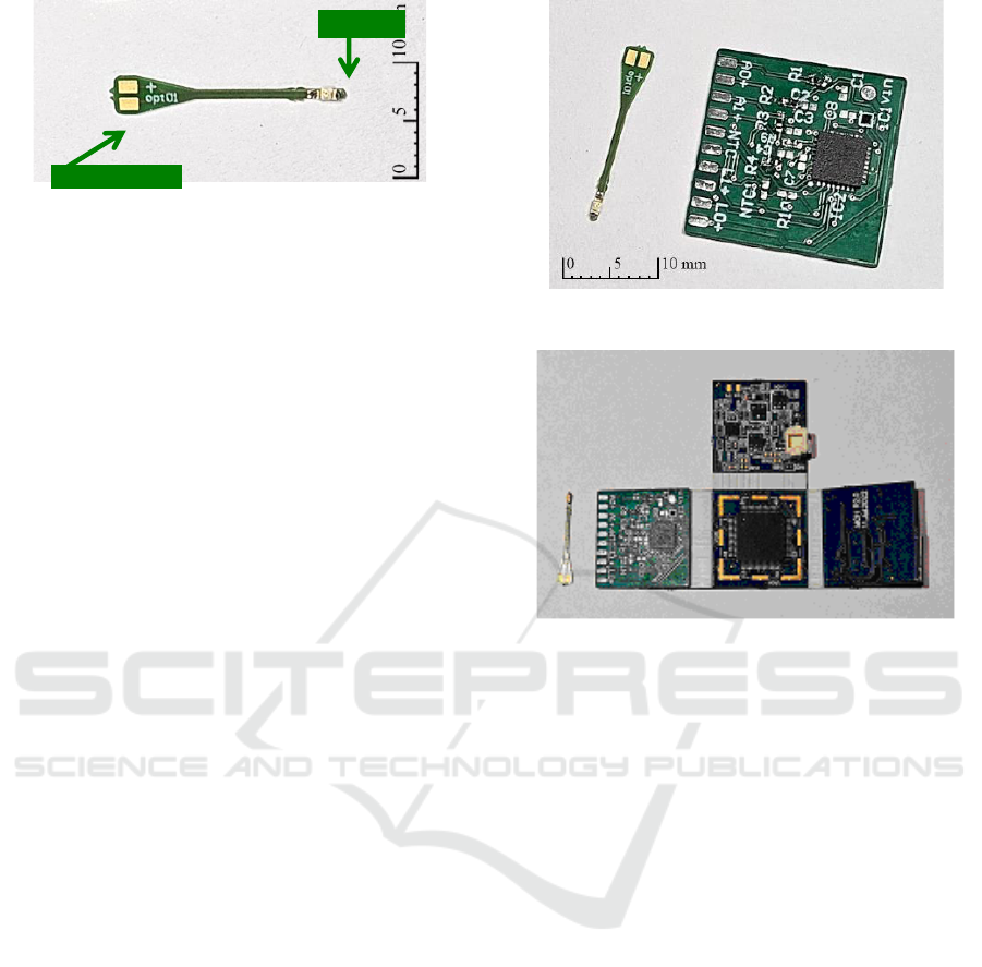
Figure 3: Photograph of an optrode module prototype with
Dialight 598-8091-107F LED.
4.2 LED Driver Circuit and Other
Components
The TLC5940 integrated circuit from Texas
Instruments was chosen to be used to control the
LEDs. Key characteristics that influenced this choice
include:
(1) Capability to control up to 16 LED
channels;
(2) Programmable and individual current control
for each channel in 64 levels;
(3) 4096-level individual PWM control;
(4) Compact size, 5.00mm×5.00mm in VQFN
version;
(5) Serial communication up to 30MHz.
The integrated circuit's communication protocol
does not follow a recognized standard, however it is
possible to use SPI with some modifications.
Additionally, a WLCSP−4 package EEPROM
measuring 0.77mm×0.77mm was included in the
design for quick recognition and configuration by the
acquisition board. To validate the project, a 20 mm x
20 mm printed circuit board was manufactured to
interconnect the aforementioned components. The
following were also included:
(1) Solder pads for 2 LEDs;
(2) Solder pads for 2 signal reading pairs, which
can be connected to an electrode, temperature sensor,
or both;
(3) Solder pads for resistors and capacitors on the
analog signal tracks for RC filter implementation;
(4) 40-pin connector, on the back of the board, for
connection to the acquisition module;
(5) Electrical test points to facilitate testing.
The optrode module, together with the interface
board is shown in Figure 4, while Figure 5 shows the
optrode module coupled to the acquisition board.
Figure 4: Optrode module and interface board.
Figure 5: Optrode module connected to the main acquisition
module.
5 BENCH TESTS
The optical power of commercial LED models and
the performance of optical pattern execution for
optogenetics applications were evaluated under
bench test conditions
5.1 Optical Power Test of LEDs
A search for LED models was conducted, and five
models were selected and tested. For the selection,
only models with an emitted wavelength close to 473
nm— the region in which CHR2 is maximally
activated—were considered.
The current of each LED was adjusted to close to
its nominal value and close to its maximum value by
varying a potentiometer to adjust the current while it
was measured by a Fluke 287 multimeter, and the
optical power was recorded using the Thorlabs
PMD100D Optical Power Meter setled to 473nm
wavelength in an environment with a dark chamber.
contacts
LED
EM4Health 2025 - Special Session on Electromagnetic waves for healthcare
1076
5.2 Optical Pattern Execution Tests for
Optogenetics
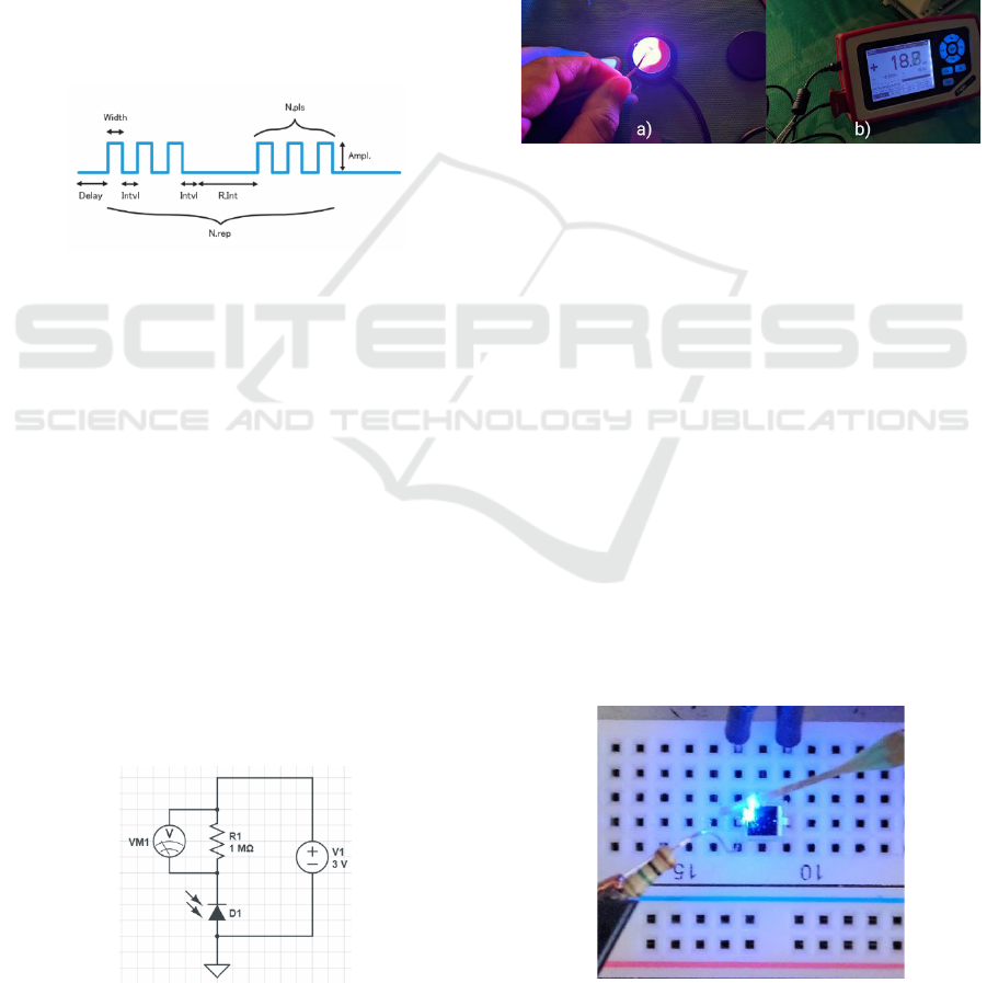
Figure 6 illustrates a structure that was created to
describe the pulses to be executed. The parameters
that can be configured when defining stimulation
pulses are listed below:
(1) Amplitude: The amplitude of the optical pulse
will be given by the current control, being directly
related to the light intensity
(2) Delay: Delay in starting activation;
(3) Width: Length of activation time;
(4) Interval: Time interval between activations;
(5) Pulse Number: Number of train pulses;
(6) Repeat Interval: Time interval between
repetitions;
(7) Repeat Number: Number of repetitions.
Figure 6: Description of a pulse pattern.
The optrode module received commands to
reproduce the following pulse pattern:
(1) Delay: 500ms,
(2) Width: 2ms,
(3) Interval: 500µs,
(4) Pulse Number: 5,
(5) Repetition interval: 2s,
(6) Number of repetition: 3.
To check the optical pulses, a circuit with a
photodiode and a resistor in series was assembled, so
that the reverse current generated in the photodiode
when sensitized by the pulse pattern of the optrode
module generates a variation in the resistor voltage.
Figure 7 illustrates the schematic of this circuit. The
voltage across the resistor is monitored on an
oscilloscope, and the shape of the generated wave is
compared to the pulse pattern performed.
Figure 7: Schematic of the optical sensor circuit for testing
pulse patterns.
6 EXPERIMENTAL RESULTS
AND DISCUSSION
6.1 Optical Power of Commercial
LEDs
In total, five LED models were tested. Each of them
has been tested close to its rated current and its
maximum current, when possible. Figure 8 shows the
LED approach to the sensor in the image on the left
and the measurement panel on the right. Table 1
summarizes the results obtained.
Figure 8: Optical power test: (a) sensitive component and
(b) power measurement.
The LED model DA2432, manufactured by Cree,
demonstrated high light power (18.7mW) despite its
small physical size. Furthermore, its maximum current
is 100mA. However, its compact dimensions (240 µm
by 320 µm) make soldering challenging and increase
the risk of losses. Additionally, obtaining more units
of this model was not possible, as it is an obsolescent
product. Cree's CLM3A-BKW-CUAVA453 model
exhibited similar optical power levels at a lower
current, but its volume is approximately 652 times
larger. Roithner's B5B-437-IX model delivered
slightly more than half the optical power of the
previous models and has the largest physical size
among them. Dialight's 597-3601-207F model
presented the lowest optical power even though it was
larger than the 598-8091-107F model from the same
brand, which, in turn, obtained 5.15mW of optical
power and the second smallest size among them.
Figure 9: Measurement of the performed pulse pattern.
Development of Optrodes and Instrumentation for Wireless Optogenetic Application
1077
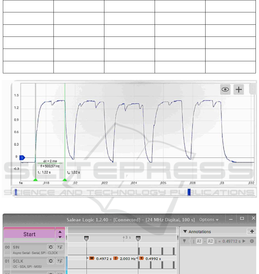
Table 1: Measurements of LED power.
Supplier/Model
Dimension [mm]
Wavelength [nm]
Nominal current [mA]
Measured optical
power [mW]
Cree DA2432
0.240.320.14
470
20
5.6 @ 19.6mA
18.7 @ 99mA
Cree CLM3A-BKW-
CUAVA453
2.72.01.3
470
20
18.8 @ 19.6mA
10.4 @ 10.0mA
Dialight 598-8091-
107F
1.60.80.7
473
20
5.15 @ 19.6mA
Dialight 597-3601-
207F
3.52.81.9
465
20
1.7 @ 20mA
Roithner B5B-437-IX
5 (diameter)
468
30
8.3 @ 21mA
10.6 @ 30mA
Figure 10: Train of pulses captured by the oscilloscope.
Figure 11: Programmed delay time measured in logic analyser.
6.2 Execution of Optical Patterns for
Optogenetics
The photodiode was assembled in series with a
resistor, as shown in Figure 7. Figure 9 shows the
assembly of the photodiode and the approach of the
interface board to the LED performing the pulse
patterns. The LED used in the tests was the Dialight
598-8091-107F.
The voltage across the resistor was measured
using a Hantek 6022BL digital oscilloscope. The
captured pulse train is presented in Figure 10, where
the pulse width, inter-pulse interval, and repetition
times were analyzed.
The start delay (delay parameter) was defined as
the time interval between the last clock pulse of the
TLC5940 initial configuration transmission and the
beginning of the first pulse transmission. This
EM4Health 2025 - Special Session on Electromagnetic waves for healthcare
1078

measurement was performed using a Hantek 6022BL
logic analyzer in conjunction with Saleae Logic
1.2.40 software. The results of the configured and
measured parameters are summarized in Table 2.
Table 2: Configured values and measured values when
executing pulse patterns.
Parameter
Configured
Measured
Delay [µs]
500
497
Width [ms]
2
2
Interval [µs]
500
595
Pulse Number
5
5
Repeatition Interval [s]
2
1.98
Repeat Number
3
3
7 CONCLUSIONS
In bench tests, the optrode module successfully
reproduced the patterns required for optogenetics
experiments, demonstrating both adequate optical
power and temporal precision. These results support
the continuation of the project’s development. The
next steps include full integration and testing with the
acquisition electronics, enabling simultaneous
stimulation and signal acquisition. Subsequently, in
vivo tests will be necessary to validate the system's
performance in practical scenarios. Additionally,
developing alternative interfaces for light delivery
and signal capture, as well as exploring other
wavelengths, is of interest to expand the system's
applicability to diverse contexts.
ACKNOWLEDGEMENTS
This work was partially supported by the CNPq
(Conselho Nacional de Desenvolvimento Cientifico e
Tecnológico) through the project with the reference
CNPq 402752/2023-6. Professor João Paulo Carmo
was supported by a PQ scholarship with the reference
CNPq 305858/2023-8.
REFERENCES
Deisseroth, K., Feng, G., Majewska, A. K., Miesenböck,
G., Ting, A., & Schnitzer, M. J. (2006). Next-
generation optical technologies for illuminating
genetically targeted brain circuits. The Journal of
Neuroscience, 26(41), 10380–10386.
https://doi.org/10.1523/JNEUROSCI.3863-06.2006
Boyden, E. S., Zhang, F., Bamberg, E., Nagel, G., &
Deisseroth, K. (2005). Millisecond-timescale,
genetically targeted optical control of neural activity.
Nature Neuroscience, 8(9), 1263–1268.
https://doi.org/10.1038/nn1525
Guru, A., Post, R. J., Ho, Y. Y., & Warden, M. R. (2015).
Making sense of optogenetics. International Journal of
Neuropsychopharmacology, 18(11), pyv079.
Addgene. (n.d.). Science Guides: Optogenetics Guide.
Addgene. Available at:
https://www.addgene.org/guides/optogenetics/.
Dufour, S., & De Koninck, Y. (2015). Optrodes for
combined optogenetics and electrophysiology in live
animals. Neurophotonics, 2(3), 031205-031205.
Kim, S., et al. (2006). Electrophysiological mapping of cat
primary auditory cortex with multielectrode arrays.
Annals of Biomedical Engineering, 34, 300-309.
Chen, F. Y. B., et al. (2016). Pulse-width modulation of
optogenetic photo-stimulation intensity for application
to full-implantable light sources. IEEE Transactions on
Biomedical Circuits and Systems, 11(1), 28-34.
Freitas, J. R., et al. (2021). Simulation, fabrication and
morphological characterization of a PDMS microlens
for light collimation on optrodes. Optik, 227, 166098.
Lin, J. Y. (2012). Optogenetic excitation of neurons with
channelrhodopsins: light instrumentation, expression
systems, and channelrhodopsin variants. Progress in
Brain Research, 196, 29-47.
Development of Optrodes and Instrumentation for Wireless Optogenetic Application
1079
