
An Easy-to-Implement Multi-Channel Stepper Motor Control System
Based on MCU and FPGA
Zhen Dai
1 a
, Congcong Zhou
2 b
and Xuesong Ye
1
1
Biosensor National Special Laboratory, College of Biomedical Engineering and Instrument Science, Zhejiang University,
Hangzhou, Zhejiang, 310027, China
2
Sir Run Run Shaw Hospital, School of Medicine, Zhejiang University, National Engineering Research Center for
Innovation and Application of Minimally Invasive Devices, East Qingchun Road, Hangzhou, Zhejiang, 310016, China
Keywords:
MCU, FPGA, Trapezoidal Acceleration, Stepper, Velocity Profile, Multi-Channel.
Abstract:
This paper proposes a system architecture based on MCU and FPGA that supports the control of dozens of
stepper motors, characterized by low cost, high real-time performance, and ease of implementation. The
system leverages the integrated floating-point unit in the MCU, along with its rich peripherals and ease of
development, combined with the parallel processing capabilities and abundant I/O resources of the FPGA.
Additionally, to address various complex scenarios in medical devices, an asymmetric trapezoidal velocity
profile is implemented on the FPGA with minimal resource consumption of 528 LUTs and 353 Flip-Flops. Fi-
nally, the feasibility of the circuit is validated through logic waveform capture and oscilloscope measurements,
and position error tests on actual stepper motors demonstrate that the system is suitable for most applications.
1 INTRODUCTION
Stepper motors are used in various industrial appli-
cations where low power is required, and low speed,
torque, fast dynamics and precise positioning are im-
portant factors. For example, in medical applications
for accurate medication dosage with peristaltic pumps
or pipettes and as motion control actuators in dial-
ysis equipment (Silaban et al., 2020). The goal of
medical mechatronics is to create devices that can in-
teract with muscles, skeletal, and nervous system to
assist impaired human motor function, such as lower
limb exoskeletons. They are primarily needed by sol-
diers, individuals engaged in heavy manual labor, dis-
abled people, and the elderly. They assist in perform-
ing various movements or support gait-rehabilitation
patient. Considering factors such as size, weight,
and safety, stepper motors are a recommended choice
(Fang et al., 2023).These assistive devices require
multi-motor motion control. Pneumatic stepper mo-
tors are useful in actuating robotic systems that are
suitable for use in magnetic resonance imaging (MRI)
scanners for minimally invasive surgical interventions
such as breast biopsy, prostate biopsy, endovascular
interventions, and interventions in other organs. Driv-
ing a Pneumatic stepper requires the coordination of
a
https://orcid.org/0009-0008-6515-1308
b
https://orcid.org/0000-0001-8397-1491
multiple pneumatic pumps, valves, and cylinders to
function properly (Groenhuis et al., 2022). Mechani-
cal ventilators play a crucial role in assisting patients
with breathing while the underlying disease runs its
course. Cheaper alternatives for mechanical ventila-
tion, especially automated artificial manual-breathing
units (AMBU) bags, have received wide attention
from clinicians, researchers and policymakers, ow-
ing to fast production, economical deployment and
easy accessibility to a larger portion of the population
all across the world. The device can precisely con-
trol various ventilation parameters by driving multi-
ple stepper motors and pump valves (Kumar et al.,
2021). Protocols in the academic life science labora-
tory are heavily reliant on the manual manipulation of
tools, reagents and instruments by a host of research
staff and students. Automated laboratories offer ad-
vantages such as reducing human errors, improving
safety, and enhancing efficiency, but the biggest chal-
lenge they face is cost (Holland and Davies, 2020).
Automated laboratories often involve the transfer of
various reaction solutions, and stepper motors, as a
low-cost actuator, can meet the automation control
needs of the laboratory at a low cost.In conclusion,
electronic systems in the field of medical devices of-
ten need to drive multiple motors as actuators to per-
form various functions. In scenarios where cost is
a constraint, stepper motors are the preferred choice
Dai, Z., Zhou, C. and Ye, X.
An Easy-to-Implement Multi-Channel Stepper Motor Control System Based on MCU and FPGA.
DOI: 10.5220/0013150800003911
Paper published under CC license (CC BY-NC-ND 4.0)
In Proceedings of the 18th International Joint Conference on Biomedical Engineering Systems and Technologies (BIOSTEC 2025) - Volume 1, pages 149-156
ISBN: 978-989-758-731-3; ISSN: 2184-4305
Proceedings Copyright © 2025 by SCITEPRESS – Science and Technology Publications, Lda.
149
due to their low cost, durability, and low noise.
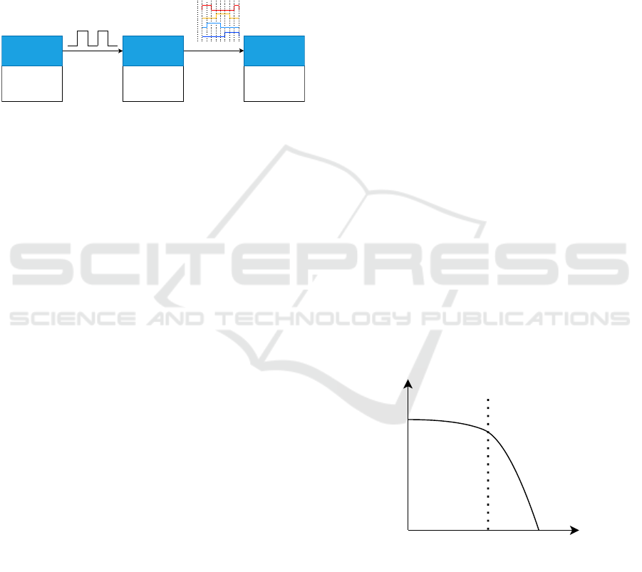
Currently, the common electronic system for driv-
ing stepper motors consists of three modules: the con-
troller, the power driver, and the stepper motor, as
shown in the Figure 1. The controller generates the
pulse sequence to drive the stepper motor, the power
driver converts the pulse sequence into a high-power,
two-phase, four-wire drive signal, and the stepper mo-
tor rotates under the changing magnetic field pro-
duced by the driver.
Ardunio
MCU
FPGA
...
LV8728
DRV8845
...
Robot
Peristaltic Pump
...
Controller
Power
Driver
Stepper
A+
A-
B+
B-
Figure 1: Normal stepper control system.
The controller is often chosen to be an
MCU(Micro Controller Unit) (Zhang and Yu, 2022;
Zhang et al., 2017; Fonseca-Campos et al., 2023),
or an FPGA(Field Programmable Gate Array) (Zunin
and Romanova, 2021; Chen et al., 2024). However,
these papers mainly discuss how to drive stepper mo-
tors on these hardware platforms, with few discussing
the hardware resources consumed.
The advantage of the MCU is that it can utilize
the FPU(Floating Point Unit) unit to perform com-
plex floating-point mathematical operations and use
timer resources to generate PWM(Pulse Width Mod-
ulation) waves at specific frequencies. However, due
to the limited I/O ports and timer resources of an
MCU, the number of stepper motors it can drive is re-
stricted. When multiple steppers are spinning at high
speeds, the MCU must calculate the next pulse period
before it arrives. Therefore, in scenarios where mul-
tiple steppers need to be driven, using an MCU re-
quires careful management of computational tasks to
ensure that calculations are completed on time, allow-
ing each motor to operate as expected. Additionally,
the high-speed rotation of multiple steppers results in
more frequent timer interrupts, which increases the
CPU’s load. These issues complicate the development
of multi-stepper motor control using an MCU, of-
ten requiring multiple MCUs to form a complex star-
shaped network. On the other hand, the FPGA bene-
fits from its parallel processing capabilities and abun-
dant I/O resources, making it much easier to drive
multiple steppers simultaneously. It is highly flexi-
ble and can be programmed according to the needs
of the application and the devices being controlled
(Boulaala et al., 2020). However, most FPGA-driven
stepper solutions involve complex floating-point mul-
tiplication, division, and square root calculations,
which can only be handled by high-performance FP-
GAs with integrated DSP hard cores or by using
vendor-provided IP cores. These FPGAs are gener-
ally more expensive compared to standard FPGAs and
consume more hardware resources.
To address these issues, this paper proposes an
MCU+FPGA solution, which combines the MCU’s
advantage of handling complex calculations with the
FPGA’s abundant I/O resources and parallel process-
ing capability. This solution is simple and feasible,
and it can drive multiple stepper simultaneously.
2 MULTI-CHANNEL STEPPER
MOTOR CONTROL SYSTEM
2.1 Trapezoidal Velocity Theory for
Stepper Motor
The torque frequency curve of the stepper motor is the
correlation curve between the output torque and input
pulse frequency of the stepper motor (bang Che et al.,
2023). As shown in the Figure 2, with the increase in
speed, the torque of the stepper decreases rapidly. The
parameter f s represents the stepper’s max starting fre-
quency, and starting the stepper at a speed greater than
this value will result in stalling and loss of synchro-
nization. Accordingly, the speed should be reduced
from the target speed to a suitable lower rate to avoid
extra and unnecessary stepping caused by shaft iner-
tia.
f(Hz)
M(N×m)
O
M
0
f
max
f
s
Figure 2: Torque frequency curve of the stepper.
To ensure that the stepper motor reaches the tar-
get speed without losing steps, various acceleration
curves have been proposed in past research, such as
trapezoidal curves, exponential curves, and S-curves.
Among them, the trapezoidal curve is widely used
in the industrial field due to its ease of implementa-
tion. To accelerate a stepper from a starting speed to
BIODEVICES 2025 - 18th International Conference on Biomedical Electronics and Devices
150
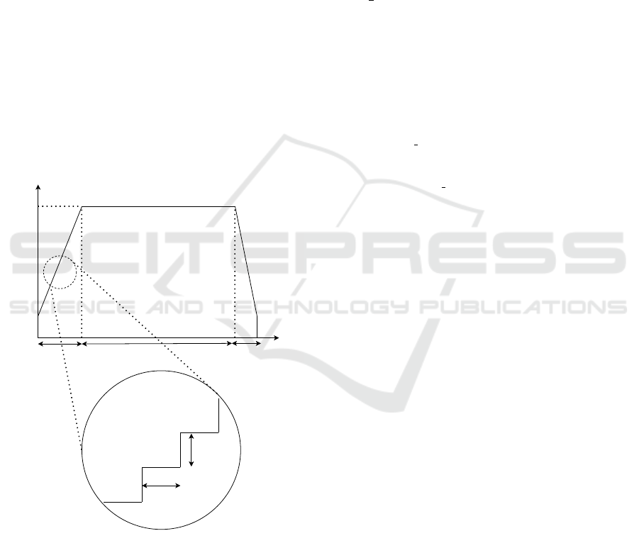
a desired target speed, the current speed just needs to
be changed at periodic intervals, which requires two
timers. The first timer is used to generate pulses with
the same frequency of stepping rate(steps per second
or SPS), which represents the ideal stepper speed.
The second one is an acceleration timer used to up-
date the first timer on a periodically. As shown in
the Figure 3, it is a graph of the trapezoidal acceler-
ation/deceleration profile and an enlarged view of the
profile’s discretization. The acceleration dv/dt can be
divided into two components: the SPS change inter-
val (when to change the speed) and the SPS variation
(how much to change the speed). Therefore, the same
acceleration can be represented by different combina-
tions of SPS change intervals and SPS variation. To
achieve the same acceleration, if the SPS variation is
set smaller, the corresponding SPS should be updated
more frequently. Conversely, when the SPS variation
is set larger, the update interval increases, but certain
SPS values may not be reached which sacrifices SPS
resolution (Quinones, 2012).
Time
f
s
f
0
PSP
Acceleration Uniform Deceleration
f
target
Change
Interval
Speed
Variation
Acceleration
t1 t2 t1
Figure 3: Trapzoidal velocity profile of the stepper.
When the stepper can rotate at the specified fre-
quency, the next challenge is how to generate a valid
trapezoidal acceleration/deceleration profile. Com-
pared to symmetric profile, an asymmetric profile al-
lows for different acceleration during the acceleration
and deceleration phases, providing more flexibility to
meet the needs of various application scenarios. For
example, in medical instruments, sampling systems
often integrate syringe pumps to achieve precise dis-
pensing of microfluid volumes. The syringe pump
moves the piston by rotating a lead screw driven by a
stepper, thereby controlling liquid aspiration and dis-
pensing. During the dispensing process, a strategy
of starting at low speed and stopping at high speed
is typically adopted (Ning et al., 2021). Take Fig-
ure 3 as an example, an asymmetric trapezoidal accel-
eration/deceleration profile can described by the fol-
lowing equations, in which v
uni
= v
0
+ A
acc
t
1
, x
acc
=
v
0
t +
1
2
A
acc
t
2
1
, x
uni
= v
uni
t
2
:
a(t) =
A
acc
0 ≤ t < t
1
0 t
1
≤ t < t
1
+t
2
−A
de
t
1
+t
2
≤ t < t
1
+t
2
+t
3
(1)
v(t) =
v
0
+ A
acc
t 0 ≤ t < t
1
v
uni
t
1
≤ t < t
1
+t
2
v
uni
− A
de
(t − t
1
− t
2
) t
1
+t
2
≤ t < t
1
+t
2
+t
3
(2)
x(t) =
v
0
t +
1
2
A
acc
t
2
0 ≤ t < t
1
x
acc
+ v
uni
(t − t
1
) t
1
≤ t < t
1
+t
2
x
acc
+ x
uni
+ v
uni
(t − t
1
− t
2
)−
1
2
A
de
(t − t
1
− t
2
)
2
t
1
+t
2
≤ t < t
1
+t
2
+t
3
(3)
Based on the equations and the figure, it can be
seen that the following variables determine the shape
of the trapezoidal velocity profile:
1. Start speed
2. Acceleration
3. Acceleration phase steps
4. Uniform speed steps
5. Deceleration
6. Deceleration phase steps
Using stepper motors is often aimed at leveraging
their ability to convert pulse signals into correspond-
ing displacement increments. Thus the total number
of movement steps is the most critical parameter, and
the acceleration and deceleration steps can be deter-
mined by the ratio of the total steps, while the constant
speed and stop speed are jointly determined by the
initial speed, acceleration/deceleration, and the num-
ber of steps in the acceleration/deceleration phases.
Additionally, the velocity profile is limited by the fol-
lowing factors due to the mechanical characteristics
of each motor:
1. Maximum start speed
2. Maximum uniform speed
3. Maximum acceleration/deceleration
When the pulse frequency received by the motor ex-
ceeds these limits, it can result in motor stalling,
missed steps, or in severe cases, burnout, so these fac-
tors must be carefully controlled.
An Easy-to-Implement Multi-Channel Stepper Motor Control System Based on MCU and FPGA
151
2.2 The Construction of the
Multi-Channel Stepper Motor
Control System
From the above analysis, it can be observed that once
a valid trapezoidal velocity profile is determined, gen-
erating the pulse sequence corresponding to the pro-
file online only requires updating the motor speed
using timers and adders according to the parameter.
The validation of the velocity profile, however, must
be computed before generating the profile via equa-
tions. Due to the programmable hardware character-
istics of FPGA, it is convenient to write a large num-
ber of timers and adders as needed. Therefore, the
generation of the velocity profile and pulse sequence
should be handled by the FPGA. The MCU, on the
other hand, is easier to program and modify, interacts
conveniently with users via peripherals, and its inte-
grated FPU makes it ideal for calculations. Hence,
user interaction and velocity profile validation should
be managed by the MCU. Based on the above analy-
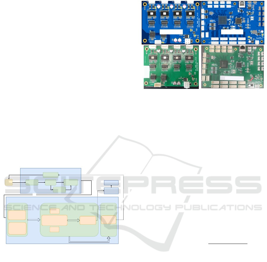
sis, the system is designed as shown in the Figure 4
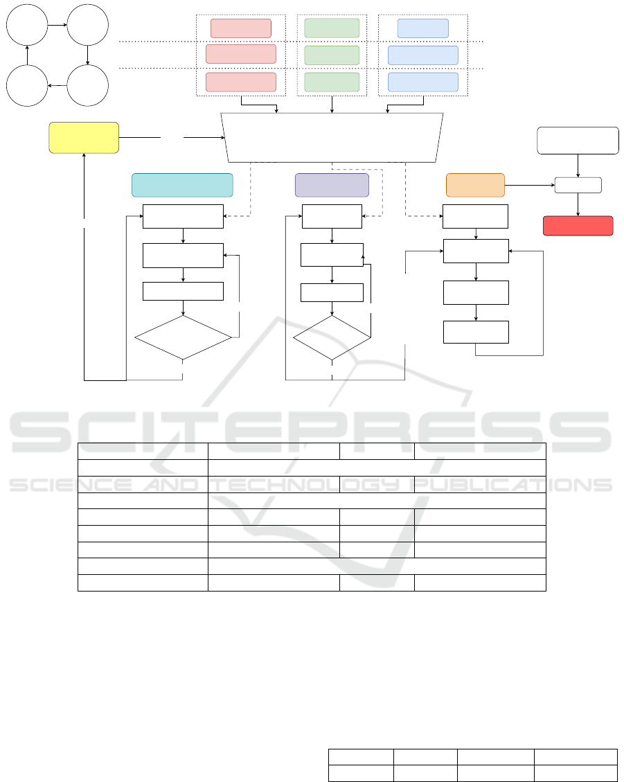
and the hardware platform is shown in the Figure 5.
User
UART
MCU
Parameter
check
Parameter
calculation
Parameter
correction
SPI
Command
encapsulation
FPGA
Command
Decapsulation
Decapsulation of
normal function
comands
Decapsulation of
trapezoidal
velocity profile
parameters
Stepper Motion Control Stepper State
Report
Reset
module
Trapezoidal velocity profile
generation module
PWM generation
module
Command
and
Parameters
Pulse period
count value
Stepper Motor
Driver
Stepper Motor
Position, Reset state, Moving state...
State
encapsulation
SPI
State
decapsulation
UART
Stop
module
Figure 4: The scheme for the multi-channel stepper motor
control system based on FPGA and MCU.
The MCU interact with the user through the se-
rial port and receive commands such as stop, reset,
and run using trapezoidal velocity profile, it also re-
turns the stepper motor’s motion status to the user.
If the user inputs illegal velocity profile parameters,
the MCU ensures that the total number of steps re-
mains unchanged and then corrects the rest parame-
ters to valid values. The program flow is illustrated
in the Figure 6. Communication between the MCU
and FPGA is conducted using two sets of high-speed
serial communication (SPI), which doesn’t consume
too many I/O resources. One set is used for the MCU
to issue commands and velocity profile parameters,
while the other set is used for querying the motor’s
motion status and position. The FPGA receives and
parses the commands and velocity profile parameters,
Power Driver MCU+FPGA
Figure 5: The hardware platform for the multi-channel step-
per motor control system based on FPGA and MCU.
activates the specified logic function modules, and
the resulting pulse sequence drives the stepper motor
through the motor driver board.
2.3 Implementation of the Trapezoidal
Velocity Profile on FPGA
The pulse is typically generated by a timer that counts
the clock signal, maintaining the I/O output at a high
level for a certain duration and then at a low level for
the remaining time. The pulse period is determined
by the counter value. Thus for a pulse with a fre-
quency value of SPS, the corresponding clock count
value is determined by the following Equation 4. Due
to the fixed clock frequency, it is not possible to gen-
erate pulses of any arbitrary frequency, so the actual
generated pulse might differ slightly from the desired
one.
clock count value =
clock f requency
SPS
(4)
The pulse generation is handled by an independent
logic module. This module receives a system clock
count value and generates a pulse with the corre-
sponding period. After generating the pulse, it sends
a completion signal, indicating that the stepper has
completed one step. To enable real-time generation of
the trapezoidal velocity profile, a state machine-based
module is designed. This module receives the veloc-
ity profile parameters and pulse completion signals,
and it outputs the current pulse period count value to
the pulse generation module.The entire process con-
sists of four states:
1. IDLE: Listens for the start signal and stores the
velocity profile parameters.
2. ACCEL: Updates the stepper motor’s speed based
on the set acceleration.
BIODEVICES 2025 - 18th International Conference on Biomedical Electronics and Devices
152
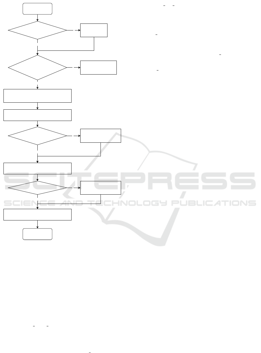
Input trapezoidal
velocity profile
parameter
N
start speed > maximum start speed ?
N
acceleration/deceleration
>
maximum acceleration/deceleration
?
Y
correct start speed to
maximum start speed
correct
acceleration/deceleration to
maximum
acceleration/deceleration
Y
calculate the acceleration/deceleration time intervals
based on the acceleration/deceleration and the preset
speed variation
calculate the uniform speed based on start speed,
acceleration phase steps and acceleration
Y
N
uniform speed > maximum uniform speed ?
reduce acceleration phase steps
to ensure that uniform speed is
maximum uniform speed
calculate the end speed based on uniform speed,
deceleration phase steps and deceleration
N
Yend speed < 0 ?
calculate the new uniform phase steps
reduce deceleration phase steps
to ensure that end speed is
positive
output corrected
trapezoidal velocity
profile parameter
Figure 6: The program flow of trapezoidal velocity profile
correction.
3. UNIFORM: Maintains the stepper motor’s speed
during the constant-speed phase.
4. DECEL: Updates the stepper motor’s speed based
on the set deceleration. After generating all the
necessary steps, the system returns to the IDLE
state.
The module mainly consists of four registers and
a multiplexer:
1. remaining steps reg: It stores the remaining steps
in the acceleration, constant speed, and decelera-
tion phases. After each completed step, it decre-
ments by one. When the count reaches zero, it
triggers a signal that changes state reg to the next
state and reloads the step count for the next phase.
2. interval cnt reg: It stores the clock count for up-
dating the SPS interval. When the count decre-
ments to zero, it triggers the SPS update signal
and reloads the count value.
3. SPS reg: It stores the discrete value of the current
velocity profile at the current moment. Initially,
it is assigned the start speed, and when it receives
the SPS update signal, the SPS reg is updated to
achieve acceleration/deceleration.
4. state reg: It stores the current state of the state
machine and, in different states, selects the corre-
sponding movement parameters for calculation.
The detailed implementation is shown in the Fig-
ure 7.
3 RESULTS AND DISCUSSION
3.1 Simulation and Actual Waveform
To verify whether the generated velocity profiles meet
expectations, three scenarios were set up: double
acceleration, double deceleration, and equal accel-
eration/deceleration, with different motion parame-
ters detailed in the Table 1. An embedded online
logic analyzer in the FPGA captured the ideal ve-
locity profiles generated by the trapezoidal velocity
profile generation module, along with the PWM fre-
quency from the PWM generation module. Oscil-
loscope measurements of the pulse waveform were
taken, as shown in the Figure 8. Images from left to
right are three scenarios: double deceleration, equal
acceleration/deceleration, and double acceleration.
Overall, the generated PWM frequency closely
followed the velocity profiles. However, it is impor-
tant to note that upon zooming in on the waveforms,
discrepancies can be observed between the actual pro-
duced frequencies and the generated velocity profiles.
The primary reason is that the SPS will be updated
several times during a long pulse period. As a result,
the next pulse can only be generated at the newest
target frequency after the current pulse period fin-
ishes. Additionally, the actual pulse frequency pro-
duced may differ slightly from expectations due to
the resolution limits imposed by the system clock fre-
quency. The oscilloscope pulse waveform images il-
lustrate how the pulse density varies over time, fol-
lowing the trend of the generated trapezoidal veloc-
ity profile. Using the oscilloscope’s measurement
function, it was observed that a total of 500 pulses
were generated during the motion process, with the
pulse frequency in the steady-state being approxi-
mately 13kHz, which aligns with the expected result.
An Easy-to-Implement Multi-Channel Stepper Motor Control System Based on MCU and FPGA
153
Divider
Pulse cycle cnt
remainning_steps_reg
reload
remaining_steps
state_reg
SPS_incre_steps
accel_interval_cnt
accel_steps
none
none
uniform_steps
decel_steps
decel_interval_cnt
SPS_decre_steps
remaining_steps --
N
Y
Change
remaining_steps == 0?
wait for one pulse
completion signal
interval_cnt_reg
reload
interval_cnt
wait for system
clock
interval_cnt --
N
interval_cnt == 0?
SPS_reg
remainning_steps
interval_cnt
SPS_variation
load SPS_start
wait for update
signal
create update signal
Y
add SPS_variation
update SPS_reg
FPGA System Clock
Frequency
IDLE ACCEL
UNIFORMDECEL
remainning_steps
Select
Multiplexer
ACCEL DECELUNIFORM
interval_cnt SPS_variation
Figure 7: The implementation of trapezoidal velocity profile generation module.
Table 1: The motion parameters in three scenarios.
Parameter Double Deceleration Symmetry Double Acceleration
Start Frequency 6400Hz
Accel Interval 25us 25us 12.5us
SPS Incre Variation 8
Accel Steps 200 200 100
Uniform Steps 200 100 200
Decel Interval 12.5us 25us 25us
SPS Decre Variation 8
Decel Steps 100 200 200
3.2 Position Accuracy of Stepper
Movement
To verify the feasibility of the system and the effec-
tiveness of the trapezoidal velocity profile algorithm,
a 42-stepper motor was selected, controlled via the
LV8728 driver, which supports up to 128 micro-steps.
The motor’s rotational angle was measured using the
MT6701 magnetic encoder chip to assess angular er-
ror. After setting the micro-step count to 32, the mo-
tor was controlled to rotate 1, 10, and 100 rounds,
with each experiment repeated 10 times. The aver-
age error values are shown in the Table 2. From the
data, it can be observed that there is still some devi-
ation between the actual and ideal rotation angles. A
potential cause for this discrepancy is the discontin-
uous change in acceleration. As the number of revo-
lutions increases, the cumulative error grows as well,
but it remains within 1.8
◦
, the step angle of the motor.
Therefore, this level of control accuracy is sufficient
for most applications where high precision is not re-
quired.
Table 2: Angle displacement errors with different Rounds.
Rotation 1 Round 10 Rounds 100 Rounds
Error(
◦
) 0.088 0.175 1.165
3.3 FPGA Resource Utilization
As mentioned above, the trapezoidal accelera-
tion/deceleration implementation in FPGA primarily
BIODEVICES 2025 - 18th International Conference on Biomedical Electronics and Devices
154
ACCEL UNIFORM DECEL ACCEL UNIFORM DECEL ACCEL UNIFORM DECEL
ACCEL UNIFORM DECEL UNIFORM DECELACCEL
Figure 8: The generated real-time velocity profile, the actual produced velocity profile, and the produced pulse waveform
graphs in three scenarios.
involves registers for recording motion parameters,
counters for timing, and a divider. However, many
synthesis tools cannot generate an efficient division
operation, consuming too many resources. To ad-
dress this, a custom pipeline divider was implemented
based on the shift-and-subtract algorithm. The divi-
dend is a fixed-width constant value (system clock of
50MHz, corresponding to a 26-bit width), while the
divisor is the dynamically changing target PWM fre-
quency. The total computation time consists of the
switching time between the states and the width of
the dividend. Thus the total computation time is 27
system clock, which is 540ns at the 50MHz system
clock. It’s important to ensure that the speed update
interval does not fall below 27 clock cycles, other-
wise, the divider will not be able to keep up with the
velocity profile.
This paper compares the proposed solution with
other studies in terms of its ability to generate asym-
metric velocity profiles and the types of computations
implemented on FPGA implementations, as shown
in the Table 3. The FPGA resource consumption
after deploying this solution on the Pango Logos
PGL50G platform is also summarized in the Table
4. Since this approach avoids complex computations,
both the trapezoidal velocity profiles generation mod-
ule and the PWM generation module use relatively
few resources, making it well-suited for implement-
ing multi-channel stepper motor control systems. As
shown in the table, the trapezoidal acceleration and
deceleration control for a single motor occupies less
than 1.5% of the total FPGA resources. If the en-
tire FPGA is utilized for instantiating this functional
module, it can theoretically control at least 65 stepper
motors simultaneously. This design has already been
implemented in a compact fully automated chemilu-
minescence immunoassay analyzer, where it currently
controls 20 stepper motors concurrently.
Table 3: Resources usage of different entity.
Work
Asymmetric
Profile
Generation
Types of
Computations
(Chen and Su, 2008) Unable 3
(Chen et al., 2024) Unable 4
(Cho et al., 2009) Able 4
Proposed Able 2
4 CONCLUSIONS
This paper presents a low-cost, high real-time perfor-
mance, and easily implementable system for control-
ling multiple stepper motors. It utilizes a MCU for
user interaction, which validate and correct input pa-
rameters to a valid range before sending them to the
FPGA. The FPGA then generates a trapezoidal veloc-
ity profile in real-time based on the parameters, con-
trolling the motors to move as expected. Unlike pre-
vious implementations on FPGA, this solution does
not involve complex mathematical calculations or
floating-point operations, resulting in lower resource
consumption and easier implementation. To address
various complex application scenarios in medical de-
vices, this paper achieves an asymmetric trapezoidal
velocity profile, allowing for more flexible motor con-
trol by modifying parameters to meet different appli-
cation needs. Finally, tests on the motor’s angular er-
An Easy-to-Implement Multi-Channel Stepper Motor Control System Based on MCU and FPGA
155

Table 4: Resources usage of different entity.
Module LUT Used LUT Util% FF Used FF Util%
Trapezoidal
velocity profile
generation
272 0.635 160 0.249
Divider 124 0.289 133 0.207
PWM
generation
132 0.308 60 0.093
Total 528 1.234 353 0.550
ror demonstrated that the error was kept within one
step angle, indicating that the velocity profile imple-
mented on the FPGA can be used in scenarios where
precision requirements are not high. Additionally,
resource consumption statistics show a total of 528
LUTs and 353 Flip-Flops were used, making it possi-
ble to control a larger number of stepper motors with
limited resources.
ACKNOWLEDGEMENTS
This research was supported by the Key Research
and Development Plan of Zhejiang Province (Grant
Nos. 2023C03094) and Zhejiang Provincial Natu-
ral Science Foundation of China under Grant No.
LY22H180006.
REFERENCES
bang Che, X., Zeng, H., Zhou, K., Xiao, H., wen Wang, X.,
Wu, X., and bo Li, C. (2023). Modeling and simula-
tion of the stepping motor operation curve. Journal of
Physics: Conference Series, 2658(1):012062.
Boulaala, M., Elmessaoudi, D., Buj-Corral, I., El Mes-
bahi, J., Ezbakhe, O., Astito, A., El Mrabet, M.,
and El Mesbahi, A. (2020). Towards design of
mechanical part and electronic control of multi-
material/multicolor fused deposition modeling 3d
printing. The International Journal of Advanced Man-
ufacturing Technology, 110:45–55.
Chen, T.-C. and Su, Y.-C. (2008). High performance algo-
rithm realization on fpga for stepper motor controller.
In 2008 SICE Annual Conference, pages 1390–1395.
Chen, Z., Gao, X., Wang, A., Liang, Z., and Zhang, X.
(2024). An online open-loop s-curve velocity profile
control method for stepping motors on fpga. IEEE
Transactions on Industrial Electronics, pages 1–11.
Cho, J. U., Le, Q. N., and Jeon, J. W. (2009). An fpga-based
multiple-axis motion control chip. IEEE Transactions
on Industrial Electronics, 56(3):856–870.
Fang, Y., Hou, B., Wu, X., Wang, Y., Osawa, K., and
Tanaka, E. (2023). A stepper motor-powered lower
limb exoskeleton with multiple assistance functions
for daily use by the elderly. Journal of Robotics and
Mechatronics, 35(3):601–611.
Fonseca-Campos, J., Reyes-Ram
´
ırez, I., Mata-Machuca,
J. L., Fonseca-Ruiz, L., Cortez-Herrera, P. N., Flores-
Cotera, L. B., and Aguilar-L
´
opez, R. (2023). Im-
plementation in microcontrollers of an algorithm for
the simple generation of speed profiles in a stepper
motor and their associated kinematics. IEEE Access,
11:143782–143803.
Groenhuis, V., Siepel, F. J., and Stramigioli, S. (2022).
Magnetic resonance pneumatic stepper motor with
multiple concentric shafts output. IEEE/ASME Trans-
actions on Mechatronics, 27(4):2379–2389.
Holland, I. and Davies, J. A. (2020). Automation in the life
science research laboratory. Frontiers in bioengineer-
ing and biotechnology, 8:571777.
Kumar, M., Kumar, R., Kumar, V., Chander, A., Gupta,
V., and Sahani, A. K. (2021). A low-cost ambu-bag
based ventilator for covid-19 pandemic. In 2021 IEEE
Biomedical Circuits and Systems Conference (Bio-
CAS), pages 1–5.
Ning, S., Long, Y., Zhao, Y., Liu, J., Bo, X., Lu, S., and
Gao, J. (2021). Research on micro-liquid dispensing
driven by a syringe pump with the consideration of air
volume. Microsystem Technologies, pages 1–14.
Quinones, J. I. (2012). Applying acceleration and decelera-
tion profiles to bipolar stepper motors. Analog Appli-
cations.
Silaban, F., Budiyanto, S., and Raharja, W. (2020). Step-
per motor movement design based on fpga. Interna-
tional Journal of Electrical and Computer Engineer-
ing (IJECE), 10:151.
Zhang, L., Liu, L., Shen, J., Lai, J., Wu, K., Zhang, Z.,
and Liu, J. (2017). Research on stepper motor motion
control based on mcu. In 2017 Chinese Automation
Congress (CAC), pages 3122–3125.
Zhang, Z. and Yu, Y. (2022). S-type speed control curve
based on the number of pulses. Journal of Physics:
Conference Series, 2196:012038.
Zunin, V. V. and Romanova, I. I. (2021). Development
and implementation of synchronous control of stepper
motors with acceleration. In 2021 International Con-
ference on Industrial Engineering, Applications and
Manufacturing (ICIEAM), pages 509–514.
BIODEVICES 2025 - 18th International Conference on Biomedical Electronics and Devices
156
