
Automatic Evaluation and Partitioning of Algorithms for Heterogeneous
Systems
Simon Heimbach
a
and Stephan Rudolph
b
Institute of Aircraft Design, University of Stuttgart, Pfaffenwaldring 31, 70569 Stuttgart, Germany
Keywords:
Heterogeneous Computing, Algorithmic Partitioning, Graph-Based Design Language, Code-Generation,
Data-Links.
Abstract:
The ever growing demand on performance and power efficiency can only be met by multiple specialised
compute engines for single tasks while costs and time to market constraints force development of programmes
for a known single micro-controller or configuration development for an FPGA. With our proposition, an
executable logic can be designed in an integral project development effort and then partitioned by an algorithm
for different compute engines depending on the user’s demand, thus generating a heterogeneous system. The
timing evaluation is not only based upon different sources like data-sheet, simulation and benchmarks but also
on the parallelism offered by FPGA. With exporters, the code for these different devices can be automatically
generated including communication channels between them to transfer all necessary data. The paper explains
the algorithm’s fundamentals and demonstrates its benefits using an example algorithm running on a micro-
controller paired with an FPGA. This shows that not only the algorithm but also the amount of data processed
is crucial for balancing a heterogeneous system.
1 INTRODUCTION
To leverage the unique abilities of every integrated
circuit (IC), it is possible to split a programme and its
algorithms into tasks optimised for different architec-
tures and implement data buses between them. Parts
of an algorithm that favours sequential execution can
be run on a controller whereas parallelisable tasks can
be swapped to an FPGA while necessary synchronisa-
tion of data is done via the buses. Every time an em-
bedded system consists of more than only one chip,
with these chips working collaboratively on the same
problem, the system is heterogeneous.
With a fine balanced heterogeneous system a de-
vice can greatly improve its overall data throughput
and responsiveness while lowering energy consump-
tion and total cost of ownership. Assumed a designed
device is too slow for a given algorithm, developers
have fundamentally three different options: Declining
the feature, using a faster and therefore more power
consuming and expensive chip or splitting the algo-
rithm into two or more tasks and running each one on
an ideal compute engine.
a
https://orcid.org/0009-0002-4758-0690
b
https://orcid.org/0009-0006-0773-1713
However, the adoption of heterogeneous systems
is hampered by problems in software development.
Not only software and configurations of different
compute engines are programmed or described in var-
ious programming languages, each specifically tai-
lored for its specific domain. There also exist dif-
ferences between libraries offered to chips that are
based on the same language – take C as an exam-
ple: The SPI-interface works very differently for
the micro-controllers Atmega (Microchip Technology
Inc., 2020, p. 172), PIC18 (Bujor, 2020, p. 2) and
STM32 (STMicroelectronics, 2012, p. 403). On top,
chips from different vendors use different tool-chains.
As a result, developers need a wide understanding of
different languages and tools to develop for a specific
architecture.
At the beginning of the development, the exact
algorithms and data-structures are mostly unidenti-
fied, and thus the perfect splits between different ar-
chitectures are also unknown. This is aggravated by
the fact that many products are developed as fami-
lies with cost-sensitive and high performance options
that often demand several divergent boundaries (Stre-
itferdt et al., 2005). In a hardware-software project
either deep knowledge of the advantages of the avail-
able hardware and a clear understanding of the ideal
Heimbach, S. and Rudolph, S.
Automatic Evaluation and Partitioning of Algorithms for Heterogeneous Systems.
DOI: 10.5220/0013153700003896
In Proceedings of the 13th International Conference on Model-Based Software and Systems Engineering (MODELSWARD 2025), pages 177-185
ISBN: 978-989-758-729-0; ISSN: 2184-4348
Copyright © 2025 by Paper published under CC license (CC BY-NC-ND 4.0)
177

hardware-topology right from the beginning is given
or time-consuming benchmarks require rewriting of
code for different architectures in order to find an ‘op-
timal’ combination.
2 BACKGROUND AND RELATED
WORK
Industry’s aspiration to support different accelerators
from a single source for embedded devices, scientific
research and immense parallel computing has been
continuous over the past years. For static analysis,
four main developing branches have evolved from
these pursuits: Cross-Compiler, Just-In-Time com-
piler (JIT), Hardware-Abstraction-Layers (HAL) and
Model-Based Systems Engineering software(MBSE).
Dynamic approaches schedule tasks between multiple
processors of the same time and can achieve a low-
latency, fail-safe system for automotive and aerospace
applications. Each proposal offers a solution for as-
pects of the problems discussed here but lack the fo-
cus on multiple different architectures in heteroge-
neous embedded systems and the automated gener-
ation of necessary source code for each target-type.
Impulsive-C, as an example for cross-compilers,
tries to translate ANSI-C-code into RTL for FPGA.
It is often used for image algorithms as it can signifi-
cantly reduce the development time, as shown by Xu,
Subramanian, Alessio and Hauck (Xu et al., 2010).
However, it is not possible to balance software for
an embedded system between multiple devices. Also,
the website of the original developer Impulse Acceler-
ated Technologies is unfortunately not available any-
more
1
so the future of Impulsive-C is uncertain.
JIT compilers are used on performance comput-
ers like notebooks, PC and server applications in the
form of peripheral drivers (e.g. GPU) or program-
ming languages (e.g. JVM). These solutions are de-
veloped by the hardware manufacturer to enable users
to take full advantage of their products. A more uni-
fied approach is offered by AMD with ROCm and
Intel with OneAPI, but these solutions are aimed at
high performance computing and cannot be adopted
on embedded systems. Java has a niche role in scien-
tific computing and can also be swapped to GPU and
FPGA with an OpenCL core (Tornado VM) but is not
widely used for microelectronics, as the lack of low
level support and the resource intense JVM make an
implementation on small components unfeasible.
A hardware-abstraction-layer (HAL) and also
drivers consist of functions that offer access to hard-
1
see: https://impulseaccelerated.com/
ware without the need for knowledge of the exact op-
erations. This enables the programming of different
models of hardware with the same source code with
the ARM ecosystem is a great example. Operating
systems and drivers take this one step further and offer
interfaces that can be used dynamically. Programmes
don’t need to be recompiled and can communicate
over a standardised format. Many major operating
systems are build upon this principle.
All these discussed solutions however have in
common that the developer has to take care of par-
titioning the programme into chunks to run those on
different devices. Also automated approaches have
been developed in the past.
There has also been academic work that focuses
on certain aspects of heterogeneous computing such
as compute architecture, memory model and dynamic
data transfer.
Lilja(Lilja, 1992) researches on splitting a pro-
gramme into tasks and scheduling those across a high-
speed-network between two computers – one based
on a regular CPU and the other equipped with a vec-
tor machine. He shows that the this approach can ac-
celerate the execution by more than a 1.000 fold, but
highly depends on the type of task and the amount of
data to be processed and shared across the network.
SymTA/S (Symbolic Timing Analysis for Sys-
tems) analyses a design space for distributed work-
loads on multiprocessor system on chip designs (Mp-
SoCs) (Hamann et al., 2006). It evaluates events
and allocates them over multiple processor nodes for
ideal latency. In a very related work tasks have been
mapped and scheduled over busses for embedded sys-
tems (Ferrandi et al., 2010). In both cases the targets
and potential code-generators are unknown to the au-
thor.
Ali et. al (Ali, 2012) describe in detail the costs of
communication between different computers in a net-
work with shared memory. Upon these models, they
experiment on the scalability of their approach. Even
though they mention CPU and GPU co-compute, it is
unclear if and how they manage to run tasks on differ-
ent type of compute architectures. The issue of mem-
ory overhead in distributed computing networks has
been focused by Xie, Chen, Liu, Wei, Li and Li (Xie
et al., 2017). In this approach, multiple processors of
the same type have been put in a network and its given
tasks dynamically scheduled between them.
The work presented in this paper, implements a
holistic solution with a single source description of
the desired system, an analytical partitioning into op-
timal architectures and exporters to generate the com-
pulsory source codes for the chosen devices. A het-
erogeneous system for embedded devices can auto-
MODELSWARD 2025 - 13th International Conference on Model-Based Software and Systems Engineering
178
AST
Partitioning
Injection
C
VHDL
RS
</>
</>
</>
Export
Compilation
Evaluation
BIN
DAT
IMG
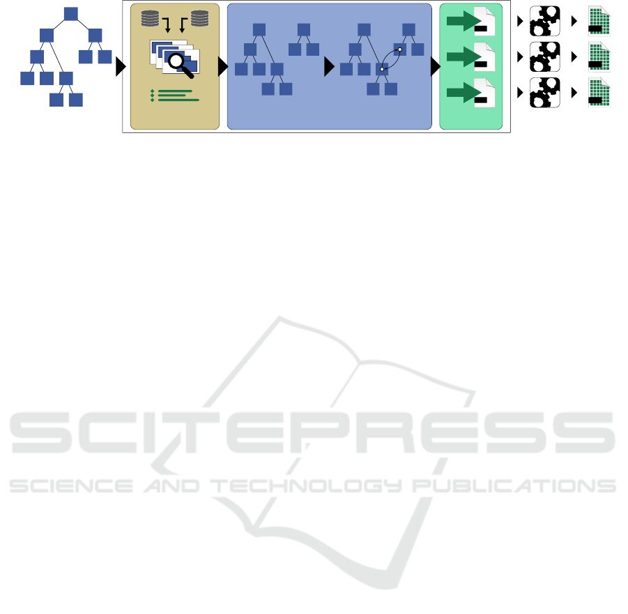
Figure 1: Big picture: Operations of an AST modelled by a user (left) is evaluated and split into Sub-AST for its perfect
device (Partitioning). When a data-movement is split, a link via a bus in automatically injected. For all AST, source-code is
generated by the corresponding exporters and the compilation- and upload-process is triggered.
matically be generated. Moreover, users are able to
create families of hardware with different architec-
tures to meet the demand for high performance and
budget options with a single design.
3 ABSTRACT LOGIC
A generic approach to an embedded system with var-
ious devices linked via busses in a single logic is in-
troduced here. A model, consisting of the operations
to describe the logic for such a system, can be ex-
ported to different architectures without any modifi-
cation and will behave in the same way on all devices.
The user does not need to rewrite code when changing
the hardware but only needs to export it for a differ-
ent target. In a second step, an algorithm has been
implemented to even split the logic between different
devices strictly based on performance metrics without
any manual work from users. Because this approach
is abstract it is called abstract logic.
Commonly used operations for programming em-
bedded systems have been abstracted in a class-
diagram and can be instantiated and connected by the
user. These linked instances are generally called a
graph or in a tighter defined subset an abstract syn-
tax tree – AST in short – like they are used in com-
pilers and lexers. Operations are connected via links
like nextop to model a sequential statement or first to
enter a block in e.g. functions or loops. Each opera-
tion can have multiple relations to other instances, for
example as arguments. In total, these AST represent
the whole logic of algorithms and programmes.
In Figure 1, the big picture of the system of ab-
stract logic is shown in a simplified manner. Develop-
ers are able to model their system in a singular AST
(left), that can be partitioned by an algorithm into an
optimal heterogeneous system based on requirements
such as runtime, energy consumption or cost. In the
first step (evaluation) all constraints are evaluated and
their containing functions tied to the chosen chip.
Such a constraint can be a bounded GPIO for exam-
ple. Also, every remaining function of the AST gets
benchmarked in regards to the requirement for every
available architecture predicated on publicly available
data – such as data-sheets, logic derived from formal
analysis and runtime measurements.
The fundamental idea for benchmarking opera-
tions in an AST is picked from E. W. Dijkstra’s 1959
paper “A Note on Two Problems in Connexion with
Graphs”(Dijkstra, 1959). The presented algorithm
finds the shorted path between two vertices in a graph
structure. A numerical weight is added to the edges
representing a distance. When the weights of con-
nected edges are summed up, the total distance be-
tween the two vertices is found. This algorithm only
follows the temporarily shortest path to ensure that
the best solution is found. This concept can be used
for path-finding and routing.
Although two major aspects differ in this paper:
• Dijkstra added the weights to the edges empha-
sising the distance between two vertices. In our
approach the vertices themself are weighted ac-
centuating the runtime of an operation
• Dijkstra took advantage of pursuing the temporar-
ily shortest path like other greedy algorithms.
This is not needed here as the AST under analysis
is linear and all its elements need to be evaluated.
When the algorithm is triggered, the given AST and
device-topology is fed into the performance algorithm
and every function is analysed in regards to their run-
time by penalising all operations in the AST. These
penalties are stored in databases and sourced either
from data-sheets, runtime analysis or simulation.
For a full evaluation of the performance on mul-
tiple devices, an additional penalty for the necessary
data-transfer is added. Only if the sum of the run-
time of all operations and the data-transfer provides
an uplift, the function is split from the original AST
(partitioning) with a new entry-point linked to an in-
stance of the chosen device to swap to. In the third
step (injection) the necessary data-transfers between
the chosen devices are automatically generated and
Automatic Evaluation and Partitioning of Algorithms for Heterogeneous Systems
179

embedded into the model.
This rebalanced AST is then handed to the ex-
porters that generate source-code for its respective de-
vice such as micro-controller, -processors and FPGA.
The injected interfaces allow the exporters to replace
in-software function-calls with driver-calls for the
respective interfaces – called target-communication
(TC). If wanted, the corresponding tool-chains are
called and the devices are programmed automatically.
The abstract logic is therefore interchangeable be-
tween different architectures and can benefit from its
unique advantages.
3.1 Sources for Time Estimation
The time required for an operation can be divided into
two units: time ∆t and clock ticks ∆clks. The data is
standardised by multiplying the time measured by the
frequency of the executing chip. Dividing this data by
the frequency will give the correct time span.
Data-Sheets: The first source of needed clocks are
data-sheets by the manufacturers of a device. Take
Microchip (former Atmel) as an example of their
AVR family of micro-controllers. The operation
CALL needs 4 cycles to perform on an AVR with
16 bit programme counter (like Atmega328)(Atmel,
2016, 63). When running the chip at a frequency of
1MHz, the resulting time span is 4µs. It has been
shown, that estimating the runtime from the AST re-
sults in only small divergence to the real runtime on
the device.
Benchmarks: If an operation consists of many in-
structions and perhaps even branches, the time span
cannot easily be modelled from its underlying instruc-
tions. A more technical approach is to benchmark the
operation on a device. Inside a loop, the operation
is executed multiple times and the time span is mea-
sured accordingly. Two drawbacks come with this ap-
proach: 1) the measurement itself is only to a certain
degree accurate and 2) different parameters of an op-
eration can lead to different execution time. A well
balanced methodology is to be chosen.
Assembly: Benchmarking however does not properly
function on more complex architectures like the Cor-
tex M4. For a more fine grained estimation the gener-
ated source code needs to be compiled into assembler
code that then get read back into the algorithm by a
lexer. For most assembler mnemonics a specific num-
ber of clocks can be derived from data-sheets for a
few mnemonics a good estimation can be drawn.
3.2 Parallelism on FPGA
When exporting the AST to an FPGA, Finite-State-
Machines (FSM) need to be modelled to execute se-
quential operations. All operations are tested on their
linear independence to achieve maximum parallelism.
Independence in this context means that in-going ar-
guments/variables of an operation are not influenced
by the results of the previous operations. Blocks of
non-influencing operations can then be put into a sin-
gle state of the FSM and the transition to its next state
will happen when all operations have finished.
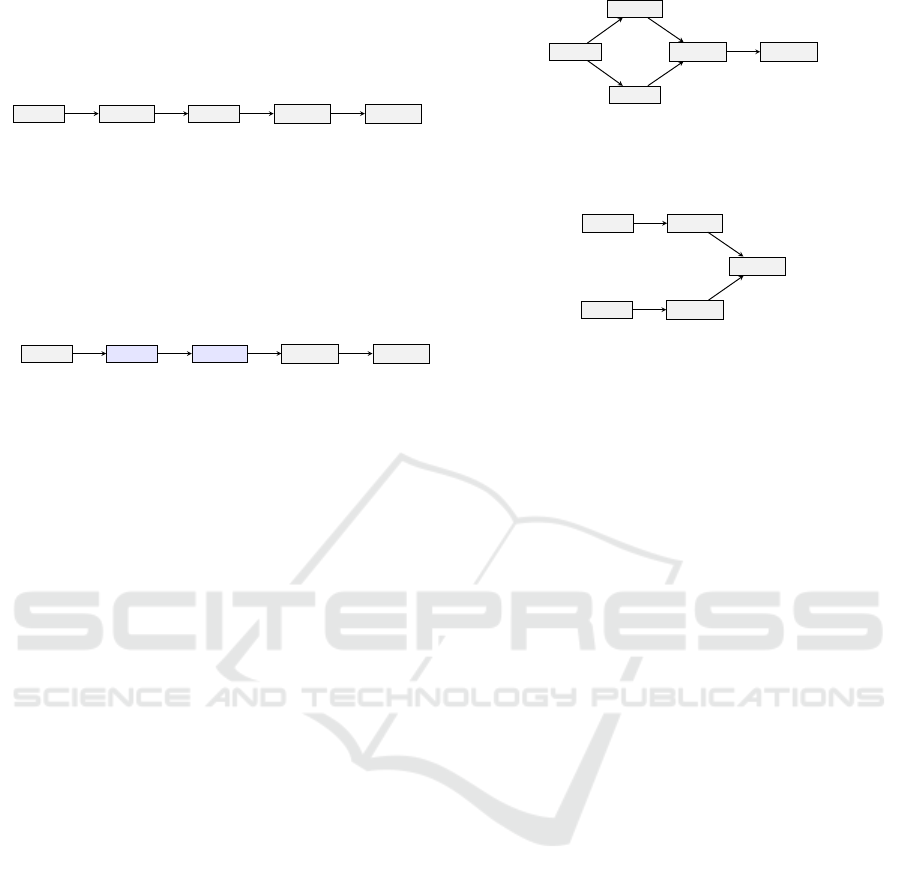
A simple example is given in Figure 2a and Figure
2b. The former represents an AST designed by a user.
The variable b is set to 1, then the operation a ← b + c
is executed. Next e is set to 2 and the operation d ←
e + f is executed. Finally there is the addition with
the terms a and d resulting in g.
The VHDL-exporter tries to put as many sequen-
tial operations in a single state as possible. In this ex-
ample a ← b+ c and e ← 2 are independent and there-
fore reduced to a single state (see Figure 2b). This
results in an FSM that can be executed in four clocks
– one clock for each state and therefore a reduction of
one clock, or 20%, over the sequential-only AST.
Operations can even be reordered to optimise par-
allelism. In this example the term e ← 2 can be pre-
poned before a ← b + c because its result is not used
as the others arguments (see Figure 3a). Operations
that write a result in a variable, are tracked to ensure
that succeeding operations that consume these vari-
ables are generated after the result is stored.
An even more advantageous parallelism can be
achieved in collection- or count-controlled loops with
constant steps and independent operations. Those are
often used in vector- or matrix-operations like addi-
tion or in traversal search algorithms. Such loops are
detected by looking for non-parallelisable operations,
such as IO-operations and return-statements, and by
calculating the dependence of variables as shown in
the previous example. If one of these conditions is
met, the loop cannot be parallelised and will be gen-
erated as an FSM. Otherwise, a parallel FSM is gen-
erated over the operations in the loop but with a re-
placement of internal signals with variables.
3.3 Analysis and Scheduling
When analysing, the first step is to determine all func-
tions that refer to constraints and those functions are
then bound to the given chip by the algorithm. These
constraints can be either a GPIO, an ADC or a com-
munication channel, e.g. UART or SPI. The contain-
ing operations in all other functions are then eval-
MODELSWARD 2025 - 13th International Conference on Model-Based Software and Systems Engineering
180
b ← 1
a ← b + c
e ← 2
d ← e + f
g ← a + d
(a) Sequential AST as modelled by the user.
b ← 1
a ← b + c
e ← 2
d ← e + f
g ← a + d
(b) Generated FSM by the VHDL-exporter with the second
and third operation in parallel.
Figure 2: From an AST to an FSM.
b ← 1
e ← 2
a ← b + c
d ← e + f
g ← a + d
(a) Reordered sequential AST after optimisation.
g ← a + d
a ← b + c
d ← e + f
b ← 1
e ← 2
(b) Generated FSM by the VHDL-exporter of the optimised
AST with the second and third operation in parallel.
Figure 3: Optimised AST to improve parallelism on FPGA.
uated. For sequential algorithms, their correspond-
ing runtime from any source of time estimations are
added. In conditions, all branches are summed up
and the highest number is then added. Loops multi-
ply their containing statements whereas the multiplier
can either be analytically determined, like in count-
controlled, or need to be tested e.g. in collection-
controlled loops with constant number of elements.
In the last case a Rust-programme is generated and
an iterator is injected that is incremented with each
step. After the loop terminates the iterator is returned
and fed back as the multiplier. This method works
only on deterministic algorithms and cannot be used
on waiting from inputs from other devices or users.
From these cases many of them can be excluded from
the evaluation due to requirements inside the contain-
ing function (e.g. IO) binding it to a certain device
anyway. The still remaining loops are marked as un-
parallelisable and exported as such.
In a hypothetical example, the operations IN and
OUT are constrained to the MCU as the signals are
bound to its pins and therefore the function main will
be exported for this chip. As an MCU executes op-
erations sequentially, the operations of a function foo
are brought in order of execution. In contrast, the ex-
porter for the FPGA parallelises the operations and
increases the execution speed. In case of such a speed
up, the exporter also injects the necessary transmis-
sion of the arguments from the MCU to the FPGA and
the return value from the FPGA back to the MCU.
3.4 Communication Between Chips
To call a function that is swapped to a different device,
the call needs to be scheduled via the underlying pro-
tocol. In the analysis process a list of all functions
is collected and for each of those two unique virtual
function ID are assigned: First for calling the function
and second to fetch the return value. On the calling
device the function call is replaced with operations to
send a byte array consisting the virtual function ID
and its arguments via the physical interface. On the
target device a new main function is generated that
listens to incoming data, accumulates those and in-
terprets the data-block. A multi-way branch checks
the incoming data with each virtual function ID and
in case of a match calls the corresponding function.
This process is called target-communication (TC in
short).
When the function is triggered on the target de-
vice, the caller can execute operations that are inde-
pendent from the functions result. Once the target has
finished executing and a return value is to be transmit-
ted, the target is sending the virtual function ID and
the return value via the bus to the calling device.
Additionally the analysis has to take shared global
variables and data-structures into account. The lat-
ter are containers storing elements that needs to be
updated and processed in a swapped function. In
most cases the system benefits from placing these data
structures directly on the target device and create a
virtual function call for access, storage or delete oper-
ations. On the primary device these operations are
then replaced with operations to transfer the corre-
sponding ID and the value.
3.5 Re-Balancing and Injection
The time span for executing the function foo on the
MCU only (t
u
) is the sum of the execution-times of
Automatic Evaluation and Partitioning of Algorithms for Heterogeneous Systems
181
all operators, the time to call each function, and re-
turning its return value. Each operation is added to
the execution time separately, as they are executed se-
quentially. When swapping the function to the FPGA,
the time for the data transfer from main to foo via the
UART bus needs to be considered, too. Here, despite
its time penalty of the data transfer, the total time for
the heterogeneous system (t
h
) might be shorter due to
the parallelisation of multiple operations. The differ-
ence between t
u
and t
h
is therefore the speed up of the
heterogeneous system.
As a drawdown, the data-transfer between the two
chips need to be taken into consideration. The max-
imum frequency and bit-width (baud-rate) for each
chip is read from a database and compared against
each other. The protocol with the highest through-
put is then chosen. The number of bits for the virtual
function ID, the arguments and the return value is cal-
culated and divided by the baud-rate to establish the
time to transfer the necessary data to the device and
back.
Once it is decided which device fits best for each
function, the whole system is re-balanced. New in-
stances of Programme are generated to target its cor-
responding device. Functions and their abstract logic
10
0
10
1
10
2
10
3
10
4
10
0
10
1
10
2
10
3
10
4
Elements [1]
t [µs]
Estimated runtime over data-size
Atmega
STM32
Atmega + FPGA
# Atmega Atmega +
FPGA
relative gain
1 2.687 25.125 -89.31%
10 9.467 25.125 -62.44%
100 76.938 25.125 206.22%
1k 751.937 25.125 2,892.78%
10k 7,501.937 25.125 29,758.46%
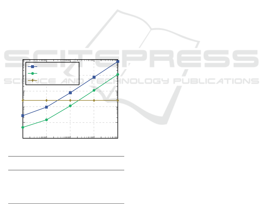
Figure 4: Estimated runtime over data sizes (at 16 MHz in
µs): With an increasing amount of data, the Atmega slows
considerably down, whereas the FPGA can benefit from
parallelising the tasks and hence achieve a constant runtime.
Once a certain amount of data has been reached, swapping
the function the FPGA is favourable.
for this chip are then moved to the new programme.
Each swapped function is assigned a unique ID that
can be referred by the original and target device.
4 A HETEROGENEOUS
EXAMPLE
A simple heterogeneous system is setup for analysis.
It consists of an MCU and an FPGA that are intercon-
nected via an UART-bus. The MCU is wired to an
analogue input which is defined as a constraint inside
the AST.
The two chips are linked via an UART-connection.
When the algorithm decides to split the logic be-
tween the two devices, code to activate the UART-
block is injected and the libraries for the target-
communication is included for both devices. The li-
brary provides functions to serialise data-packages, to
send and to receive them between the devices.
The function Main consists of a loop that calls
the function Limiter twice and toggles a GPIO-pin in
between. These pins are constrained to the Atmega
as they are – in this hypothetical example – physi-
cally bound to an LED. The algorithm therefore can-
not swap Main to another device. The function Lim-
iter does not take any arguments nor does it return any
data. It runs through an array of integers and if it en-
counters a value that is larger than a given threshold,
it will set it to a predefined constant value.
The estimated runtime for the given example has
been logged and plotted over different data sizes in
Figure 4. While the runtime of the Atmega and
STM32F3 increases linearly over the data size, the
exporter of the FPGA manages to parallelise the loop
and achieves a constant runtime driven only by the
target-communication between the devices. When the
number of elements is 33 or lower (approx. 200 for
the STM32F3), the Atmega needs less time to run
the function Limiter then the heterogeneous system
as the transmission of the arguments and the return-
value between the devices dominates the runtime.
Above that threshold, the heterogeneous system with
the FPGA and its parallelised execution aces the algo-
rithm and increases its lead over the Atmega. At 1000
elements it is almost 28 times and at 10.000 elements
300 times quicker.
5 EXPORT
During this research 3 abstract exporters and 6 spe-
cialised exporters have been developed but newer
MODELSWARD 2025 - 13th International Conference on Model-Based Software and Systems Engineering
182

ones can be inherited or completely implemented in
the future. C source code is used by the AVR- and
STM32-exporters. For both controller families C li-
braries and tool-chains are well supported by the ven-
dors. The Rust back-end is used by the Linux/x86-
exporter which provides a much better memory safety
and therefore reliability. On top, programmes writ-
ten in Rust can more easily be ported between oper-
ating systems. The VHDL-exporter is inherited by
the specified exporters for Lattice and Xilinx FPGA
and the open-source simulator GHDL. Depending on
the deviation from the base a specified exporter has
to provide functionality to generate code for IO and
timers or can optionally replace already implemented
methods for code generation in the abstract exporter.
In the exporting process, all instances of Pro-
gramme are extracted and depending in the target de-
fined in an assigned tag, the corresponding exporter
is called. For each operation in the abstract logic a
method is called that describes the necessary logic in
the programming language for the device, e.g. C for
the Atmega and VHDL for an FPGA. When export-
ing the example the Main-function including the tog-
gle of the LED is processed by the AVR/C-Exporter
while the Limiter-function is generated by the VHDL-
exporter as it was split in the previous step.
When a function-call points to a function on an-
other device, a target-communication-request (here
tc callfunc()) with the function-id and its arguments
is send to the target device. Tc waitfunc() waits until
the result is returned by the target via the interface.
On the FPGA-side, all functions are generated by
the VHDL-exporter from the logic described in the
AST. The FSM of the Main entity waits in its re-
ceiving state for incoming data from the host-device.
When all data has been transferred the FSM switches
to its exec state where it processes the data. The first
byte consist of the function’s unique id. When this ID
is correct, the arguments for the corresponding sub-
entity are assigned and the entity is activated. Once
the entity has finished the FSM transitions to the send-
state, which will reactivate the tc-core to send the re-
turned value from the before executed core. As this
example does not have arguments nor a return-value
both are omitted.
6 RESULTS AND DISCUSSION
The generated code has been compiled and tested on
an Atmega328 at 16 MHz, an STM32F3 at 64 MHz
and in GHDL as an FPGA test bench. The results
for the Atmega and STM32 are shown in Table 1.
Both chips were connected to an oscillator giving it a
precise clock source. However there are three caveats:
• the time was measured with an internal timer on
the chips that lack accuracy but is good enough
for a comparison
• an array with only one element turned out to be
too small for measurement and resulted in 0 µs
and was therefore omitted
• on the Atmega an array with a data size of 1.000
and more elements resulted in a stack overflow
and could only be measured by two nested loops
that definitely harmed the performance
At 10 elements the relative error is at 15% for the
Atmega and -18% on the STM32 respectively. It is
believed that it is that high due to a deviation in the
approximation of the loop. When the element size
grows, the real runtime on the Atmega increases more
quickly than estimated what is attributed to the nested
loops. On the STM32, the estimation is too conserva-
tive for larger datasets. Nevertheless, the derived error
is small enough for a rough estimation when partition-
ing a heterogeneous system.
7 CONCLUSIONS AND FUTURE
WORK
With the idea presented here, the optimal solution
for heterogeneous designs across different types of
architectures can be computed within a few seconds
and makes distributed computing for embedded sys-
tems economically feasible. Users can generate hard-
ware families of heterogeneous systems with different
number of features with each member running on a
different architecture for optimal performance and re-
duced costs from a single development project only.
The example that is split automatically into different
Table 1: Calculated and measured runtime (in µs) for the Atmega328 at 16 MHz and the STM32F3 at 64 MHz.
Atmega328 STM32F3
# calculated measured rel. error calculated measured rel. error
10 9.467 8 15.23% 1.469 1.8 -18.40%
100 76.938 77 -0.08% 11.313 11.8 -4.13%
1k 751.937 822 -9.32% 109.750 94.7 15.89%
10k 7,501.937 8,224 -9.63% 1,125.378 939.5 19.78%
Automatic Evaluation and Partitioning of Algorithms for Heterogeneous Systems
183

tasks, demonstrates the fundamentals of the technol-
ogy of algorithmic partitioning and the associated in-
jection of data-links.
The experiments in the paper show that the devel-
opment of embedded systems can hugely benefit from
this algorithmic partitioning approach. Even in this
simple example a manifold performance uplift can be
witnessed which is believed to be often present in any
design of an embedded system. It is demonstrated
that users can uncover these gains without any fur-
ther ado, only by modelling the algorithm in an inte-
gral AST and applying the algorithm to split it auto-
matically. This also enables the adoption of different
designs with different topologies as the AST can be
partitioned into different devices.
However, the presented methodology has draw-
backs, mainly that the auto generated code to the
exporters will always lack the potential of the code-
quality and data-footprint of hand-written code since
human developers are well aware of the holistic de-
sign and its context. Developers with deep under-
standing of the matter are likely to create better so-
lutions for a given problem. Furthermore, very com-
plex systems might still be hard to implement with
this new idea or even impossible to design at all. It
is therefore strongly believed that corner cases will
remain that can be solved faster with traditional de-
velopment tools.
Two major opportunities lay in the development
ahead:
• Utilising the idle time of devices waiting for an-
other to finish its operations. In its meantime the
calling device can compute operations ahead that
are independent from the result of the secondary
device.
• Augmenting the generation of FSM on FPGA. We
believe that an algorithm can developed to de-
tect FSM that handle streaming data better in a
pipelined design. This can lower the needed clock
cycles, reduce the resource utilisation and perhaps
also increase the maximum clock frequency.
In the future we will also focus on using the idle time
of devices waiting for another to finish its operations.
In its meantime the calling device can compute opera-
tions ahead that are independent from the result of the
secondary device.
At the same time further investigations need to
be conducted in the field of data size, energy con-
sumption and costs. A glimpse of the first problem
was caught in preparing of this paper already namely
when the function caused a stack overflow on the
micro-controller. Here, a memory usage estimation
could be introduced and would serve as a secondary
evaluation criterion when partitioning the AST. The
same is true for an FPGA: An immensely parallelised
algorithm results in lot of consumed die area and
lower potential clock speeds. Here, a pipelined ap-
proach dividing huge data into chunks and process
them sequentially can largely reduce the demand for
an FPGA. Energy consumption is often also a crit-
ical aspect in an embedded design. Here a hetero-
geneous system needs careful balancing as a data-
transfer between chips always comes at the cost of
energy that can foil the benefits gained by splitting
the algorithm on different chips. We believe that these
two additional aspects can also be added as criteria for
analysing a system.
ACKNOWLEDGEMENTS
The authors would like to thank the German Fed-
eral Ministry of Education and Research (BMBF) for
supporting the project SaMoA within VIP+. This
publication was also funded by the German Re-
search Foundation (DFG) grant ”Open Access Publi-
cation Funding / 2023-2024 / University of Stuttgart”
(512689491).
REFERENCES
Ali, J. (2012). Optimal task partitioning model in dis-
tributed heterogeneous parallel computing environ-
ment. International Journal on Artificial Intelligence
Tools, 2:13–24.
Atmel (2016). AVR Instruction Set Manual.
Bujor, I. (2020). Getting started with SPI using MSSP on
PIC18.
Dijkstra, E. W. (1959). A note on two problems in connex-
ion with graphs. Numer. Math., 1(1):269–271.
Ferrandi, F., Lanzi, P. L., Pilato, C., Sciuto, D., and Tumeo,
A. (2010). Ant colony heuristic for mapping and
scheduling tasks and communications on heteroge-
neous embedded systems. IEEE Transactions on
Computer-Aided Design of Integrated Circuits and
Systems, 29(6):911–924.
Hamann, A., Jersak, M., Richter, K., and Ernst, R. (2006).
A framework for modular analysis and exploration
of heterogeneous embedded systems. Real-Time Sys-
tems, 33:101–137.
Lilja, D. J. (1992). Experiments with a task partitioning
model for heterogeneous computing. Citeseer.
Microchip Technology Inc. (2020). megaAVR® data sheet.
STMicroelectronics (2012). Um1581 user manual.
Streitferdt, D., Sochos, P., Heller, C., and Philippow, I.
(2005). Configuring embedded system families using
feature models. In Proc. of Net. ObjectDays, pages
339–350.
MODELSWARD 2025 - 13th International Conference on Model-Based Software and Systems Engineering
184

Xie, G., Chen, Y., Liu, Y., Wei, Y., Li, R., and Li, K. (2017).
Resource consumption cost minimization of reliable
parallel applications on heterogeneous embedded sys-
tems. IEEE Transactions on Industrial Informatics,
13(4):1629–1640.
Xu, J., Subramanian, N., Alessio, A., and Hauck, S. (2010).
Automatic Evaluation and Partitioning of Algorithms for Heterogeneous Systems
185
