
Analysis of the Influence of Atmospheric Turbulence on Laser Wireless
Power Transmission
Guan Huang
1 a
, Chao Geng
2,3
and Xinyang Li
2,3
1
School of Artificial Intelligence, Optics and Electronics, Northwestern Polytechnical University, Xi’an 710129, China
2
The Key Laboratory on Adaptive Optics, Chinese Academy of Sciences, Chengdu 610209, China
3
Institute of Optics and Electronics, Chinese Academy of Sciences, Chengdu 610209, China
Keywords:
Atmosphere Turbulence, Laser Wireless Power Transmission, Adaptive Optics, Photovoltaic Array.
Abstract:
Laser Wireless Power Transmission (LWPT) technology has significant applications in many fields, such as
emergency rescue, remote power supply for aircraft, and space solar power stations. As the beam transmission
distance increases, the effects of atmospheric turbulence become significant. However, this issue has not
yet been specifically discussed. In this paper, theoretical analysis and numerical simulation experiments are
carried out to study the effect of atmospheric turbulence on the performance of LWPT. The results show that the
power transmission efficiency of LWPT is determined jointly by the mean and uniformity of the beam intensity.
Under the influence of moderate atmospheric turbulence (with C
2
n
of 8.6× 10
−16
m
−2/3
), the maximum power
of the photovoltaic array will be seriously affected (from 100% to less than 0.5%), and simply compensating
for the tilt aberration will not make a significant difference. The conclusion of this paper shows the importance
of adaptive optics (AO) systems in future long-range LWPT links.
1 INTRODUCTION
Laser Wireless Power Transmission (LWPT) is a
rapidly advancing technology in recent years. It en-
ables the wireless transmission of electrical power
through free space. Compared with traditional cable-
based power transmission, LWPT technology does
not need to consider cable laying and daily mainte-
nance, and can dynamically adjust the direction of
the radiated power. Therefore, LWPT has incompara-
ble advantages in many special scenarios(Kawashima
et al., 2007; Achtelik et al., 2011; Sprangle et al.,
2015; Mohammadnia et al., 2021), such as nuclear
power plants, oil wells, mines, remote power sup-
plement of aircraft etc. In addition, compared with
the common microwave or electromagnetic coupling
wireless power transmission technology, the laser
beam has the characteristics of short wavelength,
good directivity, and good monochromaticity. There-
fore, the equipment in the LWPT link is smaller and
lighter, and the power transmission distance is longer
(up to km level or above). For the above-mentioned
reasons, LWPT technology has attracted extensive at-
tention in recent years(Gou et al., 2023; Kim and
a
https://orcid.org/0000-0002-1255-0355
Park, 2020; Javed et al., 2022).
In 2007, N. Kawashima demonstrated a laser-
powered kite, which flew with an altitude of more
than 50 m, and a long-time stable flight operation was
successfully realized (more than 1 hour)(Kawashima
et al., 2007). In 2010, a quadcopter drone called
Pelican, developed by LaserMotive, took off at the
Future of Flight Aviation Center in Washington. A
2.25 kW laser diode array, placed 18 m away, is
used to power the drone. During the experiment, the
drone flew for 12.5 hours (150 times its original en-
durance), making it the longest hovering record for
a laser-powered aircraft at the time(Achtelik et al.,
2011). In 2015, P. Sprangle reported a laser-powered
twin propeller aerial vehicle. The experiment was
carried out indoors, and the distance between the
laser emitter and the drone was 40 m(Sprangle et al.,
2015). In 2016, M. A. Vorontsov reported the LWPT
experiment based on the coherent fiber array sys-
tems. The beam transmission distance was 7 km,
and the coherent fiber array was used to compensate
for the atmosphere turbulence to improve the perfor-
mance of LWPT(Vorontsov and Weyrauch, 2016). In
2021, A. Mohammadnia analyzed the electric power
received by laser-powered drones when using three
commercial photovoltaic materials, and a two-phase
Huang, G., Geng, C. and Li, X.
Analysis of the Influence of Atmospheric Turbulence on Laser Wireless Power Transmission.
DOI: 10.5220/0013167500003902
In Proceedings of the 13th International Conference on Photonics, Optics and Laser Technology (PHOTOPTICS 2025), pages 41-48
ISBN: 978-989-758-736-8; ISSN: 2184-4364
Copyright © 2025 by Paper published under CC license (CC BY-NC-ND 4.0)
41

cooling system was suggested for photovoltaic pan-
els to reduce the temperature of the under radiate
area(Mohammadnia et al., 2021).
In the LWPT system, the most important concern
is power transmission efficiency, which is composed
of three parts: electro-optical conversion efficiency of
the laser source, beam’s transmission efficiency in the
free space, and photo-electric conversion efficiency of
the photovoltaic array (PVA). It is well known that at-
mospheric turbulence will severely affect the wave-
front of laser beams(Guo et al., 2022), so that the far-
field intensity distribution of the laser beam changes
constantly, mainly reflected in the beam dithering,
beam spreading, and uneven beam intensity distribu-
tion.
For the PVA in the LWPT link, the size and shape
are specially designed according to the fixed beam
intensity distribution. Turbulence will invalidate this
optimized design, and then reduce the conversion ef-
ficiency of PVA. From the research in recent years,
it can be find that most experiments are carried out
indoors or outdoors at a short distance, so turbu-
lence has a limited effect. In the long-range (7 km)
LWPT experiment, the performance of the LWPT sys-
tem was greatly improved when the turbulence ef-
fect was mitigated(Vorontsov and Weyrauch, 2016).
Many papers have discussed the effect of static beam
intensity distribution (such as Gaussian) on PVA ef-
ficiency(Zhou and Jin, 2017), but the effect of turbu-
lence has not been analyzed yet. As the beam trans-
mission distance of LWPT becomes longer in the fu-
ture, it will be very valuable to study the effects of
turbulence on LWPT.
In this paper, the basic principle of the LWPT sys-
tem is briefly introduced, followed by the problems.
Then the mathematical models, including the turbu-
lence model and PVA model, are introduced, which
can be used to generate varying far-field beam in-
tensity distributions and observe the performance of
PVA. In the end, simulation experiments are con-
ducted to give qualitative conclusions. The experi-
ment results show that the maximum power of PVA
is determined jointly by the mean and uniformity of
the beam intensity. In addition, the moderate turbu-
lence (with C
2
n
of 8.6 × 10
−16
m
−2/3
) can cause a se-
vere power drop of the PVA, and only realizing the tilt
aberration compensation can not effectively alleviate
this phenomenon.
The rest of this paper is organized as follows: the
current situation and problems of LWPT are shown in
section 2. In Section 3, the effects of the atmosphere
turbulence are introduced in detail. In Section 4, sim-
ulation experiments based on turbulence with differ-
ent levels and PVA with different cells are conducted.
2 CURRENT SITUATION AND
PROBLEMS
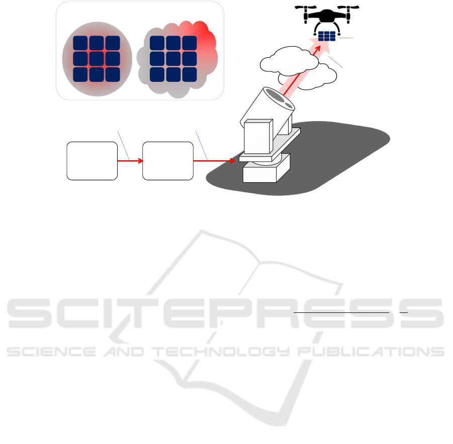
Fig. 1 shows the structural scheme of the LWPT
system. First, electric power is converted into op-
tical power by the laser source. Then, the optical
power is directed by the acquisition, tracking, and
pointing (ATP) system, and emitted by the optical an-
tenna. Laser beams reach the remoted photovoltaic
array (PVA) after long-range atmospheric transmis-
sion. In the end, the optical power is converted into
electric power by the PVA and then drives the load,
such as a drone.
In the process of free space propagation, the in-
tensity distribution of the laser beam varies randomly
due to the turbulence. The left corner of Fig. 1 shows
the PVA and the laser spot at the target plane in ideal
condition and with turbulence. The intensity distribu-
tion of the spot is generally considered to be Gaussian
distribution in ideal conditions, due to the diffraction
in laser resonators. The shape of the PVA and the
connection of the cells is usually optimized for this
situation, in order to improve the photo-electric con-
version efficiency. When the turbulence is considered,
the spot will deviate from the surface of the PVA, and
the intensity distribution becomes irregular, resulting
in a mismatch with the PVA’s design.
Here, the power transmission efficiency of the en-
tire LWPT link is represented by η, and it can be de-
termined by the following formula:
η = η
T x−io
· η
T x−oRx−i
· η
Rx−io
=
P
T x−out
P
T x−in
·
P
Rx−in
P
T x−out
·
P
Rx−out
P
Rx−in
(1)
The parameter η consists of the following parts:
1)Electro-optical conversion efficiency η
T x−io
,
which equals to the ratio of the emitted optical power
P
T x−out
to the input electrical power P
T x−in
, and it is
mainly determined by the type of the laser.
2)Beam’s transmission efficiency in the free space
η
T x−oRx−i
, which equals to the ratio of the received
optical power P
Rx−in
to the emitted optical power
P
T x−out
, and it is mainly determined by the diffrac-
tion effect, atmospheric absorption, and the occlusion
of obstacles.
3)Photo-electric conversion efficiency η
Rx−io
,
which equals to the ratio of the consumed electrical
power P
Rx−out
to the received optical power P
Rx−in
.
This parameter is determined by the PV materials, the
connection mode of PV cells, the uniformity of the
beam intensity, and the degree of matching between
the shape of the spot and the shape of the PVA. Tur-
bulence will distort the wavefront of the laser beam,
which will lead to the beam dithering, beam spread-
PHOTOPTICS 2025 - 13th International Conference on Photonics, Optics and Laser Technology
42
ATP
System
Turbulence
Laser
Source
Electric
Power
PVA
Ideal Condition With Turbulence
P
Tx-in
(W)
P
Tx-out
(W)
P
Rx-in
(W)
P
Rx-out
(W)
UAV
Figure 1: Structural of LWPT system for UAV power transmission.
ing, and uneven beam intensity distribution. These
factors will reduce the photo-electric conversion effi-
ciency η
Rx−io
even though the material and the con-
nection mode of PVA remain the same.
3 MATHEMATICAL MODEL
As shown in Section 2, atmosphere turbulence will
have a serious impact on the photo-electric conversion
efficiency of PVA. Obviously, the degree of influence
is related to the intensity of the turbulence and the
structure of PVA, and the corresponding mathemati-
cal models are shown below.
3.1 Turbulence Model
The distorted wavefront of the laser beam under
turbulent atmosphere is always represented by the
Zernike polynomial(Tyson, 2011), as shown in the
following formula:
φ(r,θ) = a
0
+
N
∑
k=1
a
k
Z
k
(r,θ) (2)
Where Z
k
(r,θ) is the k-th Zernike polynomial, and a
k
is the coefficient. The first item in the Zernike poly-
nomial a
0
is known as piston aberration, which has
no effect on the efficiency of PVA. The second and
third items (k=1 and k=2) are the tip/tilt aberrations in
the x and y directions, which cause the beam dithering
and then make the spot deviate from the PVA surface.
The higher-order aberrations (k ≥3) include defocus,
astigmatism, coma, and so on, which causes the beam
spreading and uneven beam intensity distribution.
The degree of the distorted wavefront can be char-
acterized by generating the coefficient a
k
which ac-
cords with specific statistical characteristics. Accord-
ing to Kolmogorov turbulence theory, the variance of
Zernike coefficients of each order can be represented
by(Tyson, 2011):
a
2
j
=
2.246(n + 1)Γ(n − 5/6)
[Γ(17/6)]
2
Γ(n + 23/6)
D
r
0
5/3
(3)
Where the operator < · > denotes ensemble aver-
age, and Γ(·) denotes Gamma function. The parame-
ter D is the diameter of the laser beam, and r
0
is the
atmospheric coherent length, which can be calculated
by(Tyson, 2011):
r
0
=
0.423k
2
0
sec(β)
Z
L
0
C
2
n
(z)dz
−3/5
(4)
Where k
0
= 2π/λ is the wavenumber, λ is the
wavelength, β is the zenith angle, L is the beam prop-
agation distance, and C
2
n
(z) is the well-known struc-
tural constant of atmospheric refractive index.
From Eq. 3, it can be seen that (D/r
0
)
5/3
de-
termines the variance of Zernike coefficients. In the
practical LWPT link, the area of PVA is usually at
the meter level, with the purpose of facilitating heat
dissipation. In addition, the beam is usually transmit-
ted near the Earth’s surface with a large zenith angle,
which also makes the value of r
0
small. At last, the
wavelength of the laser beam in the LWPT link is usu-
ally short (810 nm or 980 nm), in order to match the
quantum efficiency of the PV materials. As a result,
the impact of atmospheric turbulence on the LWPT
link is more serious than that of other laser transmis-
sion applications, such as directed energy and free
Analysis of the Influence of Atmospheric Turbulence on Laser Wireless Power Transmission
43
space optical communication. In the following anal-
ysis, the RMS value is used to quantify the degree of
wavefront distortion:
RMS =
r
1
D
ZZ
D
[φ(x,y)
2
]dxdy (5)
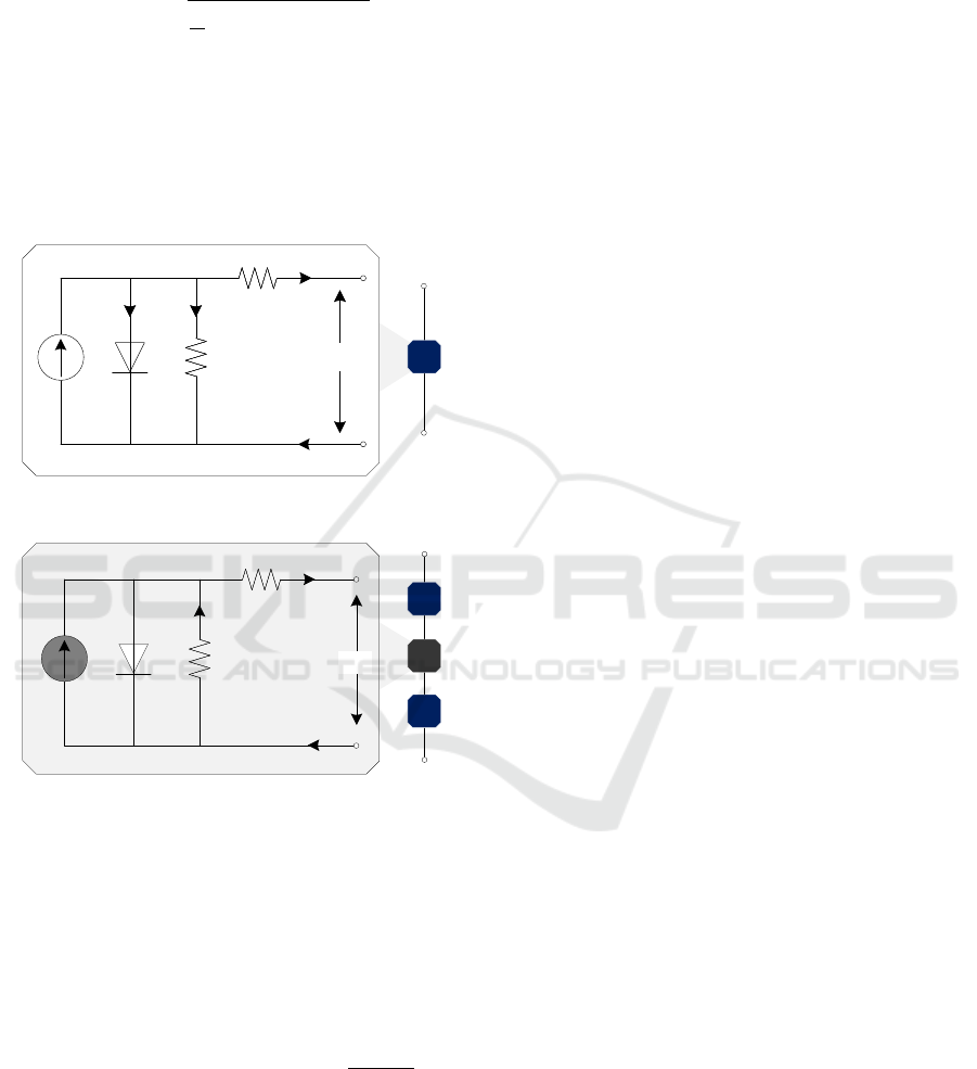
3.2 Photo-Voltaic Array Model
In practice, in order to achieve a specific volt-
age/current output, PVA is formed by multiple PV
cells in series and parallel. The simplified model of
the PV cell is shown in Fig. 2:
R
s
I
sh
R
sh
I
d
I
I
ph
V
R
s
I
sh
R
sh
I
d
I
I
ph
V
I
Figure 2: The simplified model of the PV cell.
R
s
I
R
sh
I
d
=0
I
I
ph
=0
V
c
I
Figure 3: The simplified model of the three PV cells in se-
ries.
Where the parameters I and V are the output cur-
rent and voltage of the PV cell. The three other cur-
rent parameters I
ph
, I
d
, I
sh
are the photo-generated
current, dark current, and bypass current, respec-
tively. The two resistance parameters R
sh
and R
s
are
the bypass resistance and series equivalent resistance.
Obviously, the output current I can be represented by:
I = I
ph
− I
d
− I
sh
= I
ph
(G) − I
d
(T ) −
V + IR
s
R
sh
(6)
Where G (W/cm
2
) is the irradiance of the laser
beam, and T is the temperature. The photo-generated
current I
ph
is decided by the irradiance G and the re-
ceiving area of the PV cell. From Eq. 6, it can be
find that the power of the PV cell is proportional to G
when the temperature and the receiving area remain
constant. When the cells are connected in series, the
total power can be obtained by addition.
Fig. 3 shows the three PV cells in series, and the
special is that irradiance G is not even. The middle
cell receives an irradiance of G = 0. In this case, the
photo-generated current I
ph
is approximately equal to
0. In the series circuit, the current I is equal every-
where, so the output voltage of the middle cell can be
calculated by:
V
c
= −(R
sh
+ R
s
)I (7)
The minus sign in Eq. 7 means that the voltage V
c
needs to be subtracted from the total voltage. In other
words, the middle cell consumes the power P
c
:
P
c
= V
c
I (8)
In practice, the blocked PV cell will consume
power in the form of heat, and the temperature will in-
crease, producing ”hot spot” effect, and even starting
a fire. The common way to solve the ”hot spot” effect
is to attach a bypass diode to the PV cell, with the cost
of reduced power. In summary, the output power of
PVA depends on the mean and the spatial uniformity
of the irradiance G. Therefore, when the turbulence is
considered, the beam dithering, beam spreading, and
varying beam intensity distribution will result in seri-
ous impacts.
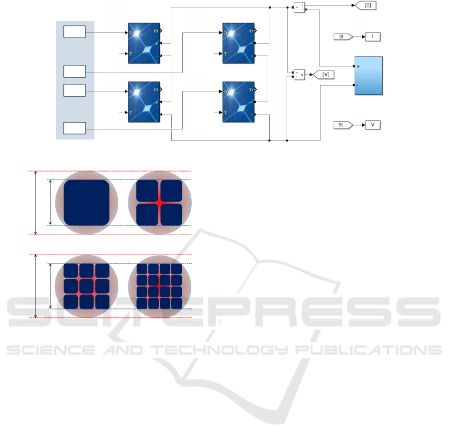
4 SIMULATION EXPERIMENTS
In this section, numerical simulation experiments are
conducted to quantify the influence of turbulence
on LWPT. The structure of the simulation system is
shown in Fig. 4, where the PVA is formed by the
series-parallel connection of the PV cells. The in-
tensity distribution of the laser beam is first spatially
divided, and then fed into individual PV cells. A
variable DC source is added to simulate the chang-
ing loads, and the output current I and the voltage V
are recorded synchronously.
The size and position of the far-field laser spot and
PVA are shown in Fig. 5. The laser beam is set to a
Gaussian beam with diameter of D. The PVA is tan-
gent to the Gaussian beam, and d is the side length.
The parameter n is used to represent the number of
PV cells in PVA. To simplify the model, gaps between
different cells are not taken into account in the follow-
ing experiments.
4.1 Influence of Single Wavefront
Aberration
The influence of single wavefront aberration on the
LWPT link is analyzed first. The RMS of the wave-
PHOTOPTICS 2025 - 13th International Conference on Photonics, Optics and Laser Technology
44
I1
I2
I3
I4
T1 T2
T3 T4
PV1 PV2
PV4
PV3
I
V
Variable DC Source
Intensity
Distributions
Recorded current
Recorded voltage
Figure 4: Structure of the simulation system.
(a) (b)
(c)
d
D
(d)
d
D
Figure 5: Laser spot and PVA with different cells. (a)n=1;
(b)n=2; (c)n=3; (d)n=4.
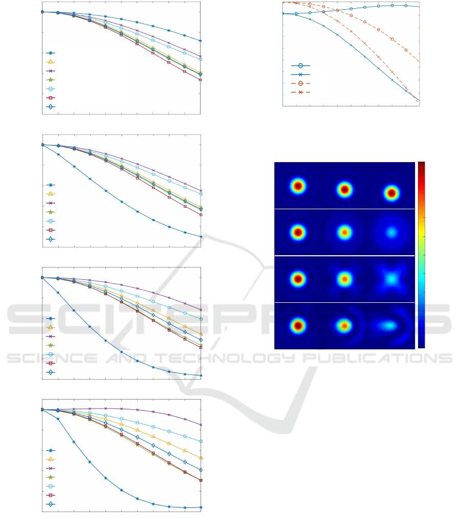
front is set to range from 0 to 2. The maximum power
of these four types of PVA is recorded, and the nor-
malized results are shown in Fig. 6.
Fig. 6 (a) shows the simulation results of the PVA
with only one cell. In this case, the PVA’s maximum
power is only determined by the mean of the beam in-
tensity. The result shows that the tilt aberration has
the least effect compared to the rest of the higher-
order aberrations. This is mainly because the higher-
order aberrations make the beam’s intensity distribu-
tion flatter, which reduces the total optical power re-
ceived by PVA.
Fig. 6 (b) to (d) shows the simulation results of
the PVA with 4, 9, and 16 cells, and the results have
made a big difference. In this case, the reduction
of the maximum power is determined jointly by the
mean and uniformity of the beam intensity. There-
fore, the tilt aberration has the greatest effect on the
PVA’s maximum power for it disrupts the beam’s uni-
formity to the greatest extent. Another interesting
phenomenon is that as the number of PV cells in-
creases, the effect of the astigmatism aberration grad-
ually decreases. When the number of PV cells is 16
and the RMS is near 1, the astigmatism aberration
even causes the maximum power of PVA to rise.
Fig. 7 explains the slight increase of the curves
when the astigmatism aberration is introduced in Fig.
6 (d), which shows the mean and MSE value of the
beam intensity received by the 16 different PV cells.
For the tilt aberration, with the increase of the RMS
of the wavefront, the mean value of the intensity re-
ceived by different PV cells decreases, whereas the
MSE value does not change much (even increases
briefly), which means that the beam’s uniformity re-
mains basically unchanged (uneven as always). For
the astigmatism aberration, the mean value of the in-
tensity decreases, whereas the MSE value also de-
creases, which means that the beam’s uniformity is
gradually improving (from uneven to uniform), so it
has a positive impact on the maximum power of PVA.
Fig. 8 shows the diffraction pattern of the corre-
sponding far-field spot, which is also consistent with
the above interpretation. The astigmatism aberration
reduces the mean of the beam intensity, but the shape
of the far-field spot is closer to square, so the intensity
received by different PV cells becomes more uniform.
4.2 Influence of Atmosphere Turbulence
In this section, the influence of atmosphere turbulence
on the LWPT link is analyzed. The first 15 Zernike
coefficients are used to generate the distorted wave-
front. The beam diameter is D=0.3 m, the wave-
length of the laser beam is λ=810 nm, the beam prop-
agation distance is 5 km, and the beam is assumed
to travel along the horizontal atmosphere. The at-
mosphere refractive index structure constant C
2
n
are
set to 0, 5.8 × 10
−17
m
−2/3
, 1.9 × 10
−16
m
−2/3
, 3.7 ×
10
−16
m
−2/3
, 5.9 × 10
−16
m
−2/3
, 8.6 × 10
−16
m
−2/3
.
The corresponding r
0
ranges from ∞ to 6 cm, which
causes the value of D/r
0
to change from 0 to 5. There
are three kinds of cases in the following simulations:
Analysis of the Influence of Atmospheric Turbulence on Laser Wireless Power Transmission
45
0.0 0.4 0.8 1.2 1.6 2.0
tilt
defocus
astigmatism
pure coma
zero curvature coma
spherical
5th order astigmatism
RMS (rad)
0.0 0.4 0.8 1.2 1.6 2.0
RMS (rad)
0.0 0.4 0.8 1.2 1.6 2.0
RMS (rad)
0.0 0.4 0.8 1.2 1.6 2.0
RMS (rad)
tilt
defocus
astigmatism
pure coma
zero curvature coma
spherical
5th order astigmatism
tilt
defocus
astigmatism
pure coma
zero curvature coma
spherical
5th order astigmatism
tilt
defocus
astigmatism
pure coma
zero curvature coma
spherical
5th order astigmatism
1.0
0.8
0.6
0.4
0.2
0.0
1.0
0.8
0.6
0.4
0.2
0.0
1.0
0.8
0.6
0.4
0.2
0.0
1.0
0.8
0.6
0.4
0.2
0.0
Normalized maximum power of PVANormalized maximum power of PVANormalized maximum power of PVANormalized maximum power of PVA
(a)
(b)
(c)
(d)
Figure 6: Relationship between the RMS of single wave-
front aberration and the maximum power of PVA. (a)n=1;
(b)n=2; (c)n=3; (d)n=4.
without turbulence, with turbulence, and with tilt cor-
rection. The experiments are repeated 20 times in
each case.
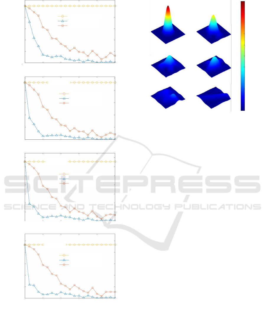
Fig. 9 (a) shows the simulation results of the PVA
with only one cell. It can be found that when the tur-
0.0 0.4 0.8 1.2 1.6 2.0
RMS (rad)
Mean of beam intensity
1.0
0.8
0.6
0.4
0.2
1.0
0.9
0.8
0.7
0.6
MSE of beam intensity
tilt
astigmatism
tilt
astigmatism
Figure 7: Statistical characteristics of the beam intensity
distribution when the number of PVA cell is 16.
tiltdefocusastigmatismpure coma
1.0
0.8
0.6
0.4
0.2
0.0
Figure 8: Diffraction patterns of the far-field spots with dif-
ferent single wavefront aberrations.
bulence is considered, the maximum power of PVA
decreases rapidly (from 1 to 0.005) with the increase
of D/r
0
. Fig. 9 (b) to (d) show the simulation results
of the PVA with 4, 9, and 16 cells, and it can be found
that as the number of cells increases, the effects of
atmospheric turbulence become more severe, and the
maximum power of PVA decreases to 0.0035, 0.0027,
and 0.0023, respectively. In addition, compensating
tilt aberration can only have an obvious effect when
D/r
0
is less than 3. This is because when D/r
0
is
larger, the higher-order aberrations in wavefront dis-
tortion start to increase, which makes the beam’s in-
tensity distribution flatter, and reduces the total power
received by PVA.
Fig. 10 shows the diffraction patterns of the cor-
responding far-field spot, where the tilt aberration is
removed. With the increase of D/r
0
, it can be found
that the spot flattens out. Therefore, even if the tilt
aberration is well corrected, the maximum power of
PVA cannot be significantly increased.
PHOTOPTICS 2025 - 13th International Conference on Photonics, Optics and Laser Technology
46
0.927635
0 1 2 3 4 5
D/r
0
0 1 2 3 4 5
D/r
0
0 1 2 3 4 5
D/r
0
0 1 2 3 4 5
D/r
0
0.0
0.2
0.4
0.6
0.8
1.0
Normalized maximum power of PVA
0.0
0.2
0.4
0.6
0.8
1.0
Normalized maximum power of PVA
0.2
0.3
0.4
0.5
0.6
0.7
0.1
0.0
Normalized maximum power of PVA
0.2
0.3
0.4
0.5
0.1
0.0
Normalized maximum power of PVA
0.657051
0.466257
without turbulence
with turbulence
with tilt correction
without turbulence
with turbulence
with tilt correction
without turbulence
with turbulence
with tilt correction
without turbulence
with turbulence
with tilt correction
0.927635
Figure 9: Relationship between the intensity of turbulence
D/r
0
and the maximum power of PVA.
5 CONCLUSIONS
In this paper, the influence of atmosphere turbulence
on the LWPT link is analyzed. Turbulence will dis-
D/r
0
=0 D/r
0
=1
D/r
0
=2 D/r
0
=3
D/r
0
=4 D/r
0
=5
1.0
0.8
0.6
0.4
0.2
0.0
Figure 10: Diffraction patterns of the far-field spots with
different intensity of turbulence D/r
0
.
tort the wavefront of the laser beam, which will lead
to the beam dithering, beam spreading, and uneven
beam intensity distribution. These factors will re-
duce the power transmission efficiency of the LWPT
link. Simulation experiments show that the maximum
power of PVA is determined jointly by the mean and
uniformity of the beam intensity, and the influence
of uneven beam intensity will be strengthened with
the increase of the number of PV cells. In some spe-
cial cases, the introduction of astigmatism aberration
even increases the maximum power of PVA. In addi-
tion, simulation experiments also show that the mod-
erate turbulence (with C
2
n
of 8.6 × 10
−16
m
−2/3
, r
0
of
6 cm) can cause a severe power drop of the PVA, this
is partly due to the large beam diameter (D=0.3 m)
and the short wavelength (λ=810 nm), for the purpose
of heat dissipation and quantum efficiency matching.
At last, the results show that with the increase of PV
cells, the effects of turbulence become stronger, and
the benefits of merely compensating the tilt aberration
are also diminishing.
In conclusion, the simulation results indicate that
in the turbulent atmosphere, it is not enough to
achieve stable PVA tracking. The compensation of
higher-order aberrations is also very important, espe-
cially in the case of PVA with more cells. In the fu-
ture, adaptive optics(Guo et al., 2022) or fiber laser
phased array can provide a solution to this problem.
In addition, in future experiments, the liquid crystal
spatial light modulator can be used to apply a control-
lable phase distribution to the beam to further verify
the simulation results presented in the paper.
Analysis of the Influence of Atmospheric Turbulence on Laser Wireless Power Transmission
47

ACKNOWLEDGEMENTS
This work was supported by the Natural Science Ba-
sic Research Program of Shaanxi (Program No. 2023-
JC-QN-0716) and the National Natural Science Foun-
dation of China (Program No. 62405247) and the
Fund of National Laboratory on Adaptive Optics,
China.
REFERENCES
Achtelik, M. C., Stumpf, J., Gurdan, D., and Doth, K.-M.
(2011). Design of a flexible high performance quad-
copter platform breaking the mav endurance record
with laser power beaming. In 2011 IEEE/RSJ Interna-
tional Conference on Intelligent Robots and Systems,
pages 5166–5172.
Gou, Y., Wang, H., Wang, J., Chen, Y., Mou, Z., Chen, Y.,
Yang, H., and Deng, G. (2023). High-performance
laser power converters for wireless information trans-
mission applications. Opt. Express, 31(21):34937–
34945.
Guo, Y., Zhong, L., Min, L., Wang, J., Wu, Y., Chen, K.,
Wei, K., and Rao, C. (2022). Adaptive optics based
on machine learning: a review. Opto-Electron Adv,
5(7):200082.
Javed, N., Nguyen, N.-L., Naqvi, S. F. A., and Ha, J. (2022).
Long-range wireless optical power transfer system us-
ing an edfa. Opt. Express, 30(19):33767–33779.
Kawashima, N., Takeda, K., and Yabe, K. (2007). Appli-
cation of the laser energy transmission technology to
drive a small airplane. Chin. Opt. Lett., 5(S1):S109–
S110.
Kim, S.-M. and Park, H. (2020). Optimization of opti-
cal wireless power transfer using near-infrared laser
diodes. Chin. Opt. Lett., 18(4):042603.
Mohammadnia, A., M. Ziapour, B., Ghaebi, H., and
Khooban, M. H. (2021). Feasibility assessment of
next-generation drones powering by laser-based wire-
less power transfer. Optics & Laser Technology,
143:107283.
Sprangle, P., Hafizi, B., Ting, A., and Fischer, R. (2015).
High-power lasers for directed-energy applications.
Appl. Opt., 54(31):F201–F209.
Tyson, R. K. (2011). Principles of adaptive optics. Boca
Raton, FL:CRC Press, Boca Raton, 3nd edition.
Vorontsov, M. A. and Weyrauch, T. (2016). Laser beam
engineering and atmospheric turbulence effects miti-
gation with coherent fiber array systems. In Propa-
gation Through and Characterization of Atmospheric
and Oceanic Phenomena, page Tu2A.1. Optica Pub-
lishing Group.
Zhou, W. and Jin, K. (2017). Optimal photovoltaic array
configuration under gaussian laser beam condition for
wireless power transmission. IEEE Transactions on
Power Electronics, 32(5):3662–3672.
PHOTOPTICS 2025 - 13th International Conference on Photonics, Optics and Laser Technology
48
