
Improving Floating Wind Turbine Stability with Evolutionary
Computation for TMD Optimization
Thayza Melo
1a
, Luciana Faletti Almeida
1b
and Juan G. Lazo Lazo
2c
1
Research and Postgraduate Department, Centro Federal de Educação Tecnológica Celso Suckow da Fonsesa,
Rio de Janeiro, Brazil
2
Facultad de Ingeniería, Universidad del Pacífico, Lima, Peru
Keywords: Offshore Wind Turbines, Tuned Mass Damper, Evolutionary Computation, Genetic Algorithms, FAST-SC.
Abstract: Wind turbines in general allow the conversion of wind kinetic energy into electrical energy, but their
installation on land is becoming increasingly complicated, due to wind speed, lower energy generation,
environmental, acoustic and visual aspects, land use, among others. In this sense, offshore wind generation
has advantages such as stronger and more constant winds, lower visual and acoustic impact, greater generation
capacity, development close to large cities, among others. Offshore wind turbines have great potential to
transform the global energy matrix, especially with the use of floating platforms that enable energy generation
in deep waters. However, these systems face significant challenges, such as pendulum loads and movements
induced by winds and waves that cause fatigue to the structure. This work proposes the use of evolutionary
computing techniques, through genetic algorithms, to optimize a passive structural control with tuned mass
damping devices (TMDs), installed in the nacelle of Floating Offshore Wind Turbines (FOWTs) of the Barge
type, aiming to mitigate these pendular effects. The TMDs are configured to act in the fore-aft and lateral-
lateral directions, and the optimization considered the standard deviation of the tower fatigue as a fitness
function, in addition to including stroke limits to adapt to the nacelle dimensions. The optimization was
performed under the free decay condition, i.e., simplified conditions and application of initial inclinations to
the platform. The simulations, conducted in the FAST-SC (Fatigue, Aerodynamics, Structures, and
Turbulence – Structural Control) software, demonstrated a reduction of more than 36% in the structural
fatigue of the tower compared to systems without structural control and an improvement of more than 11%
compared to systems with unidirectional TMD. The results reinforce the effectiveness of passive structural
control with bidirectional TMD in mitigating vibrations and increasing the reliability of floating offshore
turbines, offering an efficient approach to improve the structural reliability of the system.
1 INTRODUCTION
The growing demand for renewable energy sources
has driven the development of offshore wind turbines
as a promising alternative for electricity production.
Although these wind turbines are installed on floating
platforms, designed to exploit stronger and more
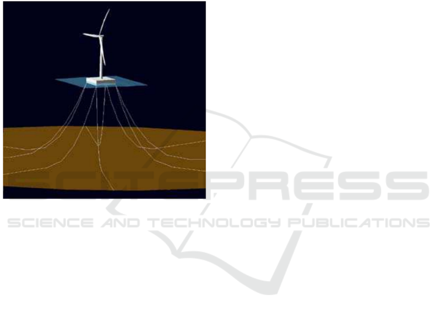
consistent winds in deep waters (60m to 900m depth),
they face significant challenges such as wind and
wave-induced pendulum loads (Vijfhuizen, 2006),
shown in Fig. 1. Floating Offshore Wind Turbines
(FOWTs) can have diverse types of bases for
a
https://orcid.org/0000-0002-0268-5803
b
https://orcid.org/0000-0001-7149-8350
c
https://orcid.org/0000-0001-7782-118X
buoyancy, with the Barge being a stable, economical,
and advantageous option for great depths (Villoslada
et al., 2022), therefore chosen for the simulations in
this project.
Research in the field of FOWTs aims to improve
energy production and avoid negative interference
from wind and waves by controlling vibrations and
reducing structural fatigue (Olondriz et al., 2019). To
this end, various forms of structural control have been
explored over the last decade. Passive control using
Tuned Mass Dampers (TMDs) is one of the most
promising for FOWTs when installed in the nacelle,
Melo, T., Almeida, L. F. and Lazo, J. G. L.
Improving Floating Wind Turbine Stability with Evolutionary Computation for TMD Optimization.
DOI: 10.5220/0013171900003905
In Proceedings of the 14th International Conference on Pattern Recognition Applications and Methods (ICPRAM 2025), pages 475-484
ISBN: 978-989-758-730-6; ISSN: 2184-4313
Copyright © 2025 by Paper published under CC license (CC BY-NC-ND 4.0)
475

the uppermost and heaviest part of the wind turbine
(Zuo et al., 2020).
In all projects, the TMD design is optimized to
reduce vibrations and improve wind turbine
performance. Parameters such as stiffness, damping
and mass are adjusted for this purpose. Adjustment
methods include frequency adjustment, genetic
algorithms (GA’s) and surface graphs. The
limitations in the TMD course are little explored,
commonly assuming fixed and simplified values, in
addition to using reduced models of the system in the
optimization loop (Chen et al., 2021). Only one work
(Villoslada et al., 2022) used GA for optimization
including TMD travel limitation and stop
configuration as variables. Although it achieved
satisfactory results in the simulation, it only
considered forward-reverse TMD, did not consider
the side-to-side TMD, nor did it include its variables
in the optimization cycle.
In this context, this work aims to optimize, using
an evolutionary algorithm, a passive structural control
system consisting of two TMDs installed in the
nacelle of a barge-type FOWT, in the fore-aft and
lateral directions. A genetic algorithm is used to
adjust the TMD system parameters, such as mass,
stiffness, damping, stroke limitation, and stop
variables, with the objective of mitigating vibrations
in the structure, platform tower pitch, and turbine
bending mode. In the optimization cycles and FOWT
tests, the simulation is performed with FAST-SC
(Fatigue, Aerodynamics, Structures, and Turbulence
– Structural Control) software, considering the free
decay of the system.
Figure 1: External forces acting on a FOWT (Butterfield
et al., 2007).
This work is organized as follows: Section 2
presents the theoretical framework and literature
review, Section 3 presents the proposed
methodology, Section 4 shows the results obtained,
finally Section 5 addresses the conclusions.
2 LITERATURE REVIEW
Most wind power generation is conducted by three-
blade horizontal-axis wind turbines located in
sparsely populated coastal areas or on onshore fields
(Picolo et al., 2014). These turbines consist of blades,
rotor (hub), gearbox, generator, nacelle, support
tower, and brake system. The nacelle houses essential
components such as the gearbox and generator, while
the support tower elevates the turbine to optimal
heights for energy generation. The brake system
controls blade speed, especially during storms. They
also have a direction sensor to orient the blades to
capture the best frontal wind (Figueiredo, 2019).
2.1 Offshore Wind Turbines and Their
Technologies
In recent years, there has been a gradual shift towards
offshore wind energy due to favourable wind
resources and proximity to coastal urban areas.
Offshore turbines take advantage of higher and less
turbulent wind speeds, providing greater energy
efficiency. They share technology with onshore
turbines with structural adaptations for different
water depths (Costoya et al., 2020). Fixed turbines in
shallow waters present complexity and excessive
costs, as well as environmental impacts and space
limitations. On the other hand, floating turbines in
deep waters (60m to 900m depth) offer reduced costs,
simplified assembly, and less environmental impact,
making them more viable for offshore deployment
(Hu & He, 2017).
FOWTs offer the flexibility of installation at
various ocean depths, up to 900m, expanding the
possibilities for deployment sites. They are
categorized into Barges, Spar Buoys, and Tension
Leg Platforms (Villoslada et al., 2022). The Barge is
stable and mobile, equipped with fin plates to avoid
stresses on the structure, while the Spar Buoy is
challenging for fabrication and installation due to its
weight concentrated at the lowest point. The Tension
Leg Platform is more innovative and riskier,
submerged with a star-shaped geometry. The stability
of the floating base is ensured by anchoring elements
such as mooring and tensioning, with three main
types: catenary, mechanically tensioned moorings,
ICPRAM 2025 - 14th International Conference on Pattern Recognition Applications and Methods
476
and Tension Leg Platform (TLP) anchors (Jonkman,
2007).
Among these options, Barge-type platforms,
stabilized by flexible or catenary mooring, are more
promising and economical for deep waters (Chen et
al., 2021). For this study, the NREL 5MW turbine
supported by the ITI Energy Barge, developed by the
National Renewable Energy Laboratory (NREL) -
USA, was chosen. An illustration of the barge with
the NREL 5MW turbine is shown in Fig. 2.
Figure 2: FOWT NREL 5MW and ITI Energy Barge (G. M.
Stewart, 2012).
2.2 Structural Control
Structural control aims to reduce loads on buildings
and bridges due to waves and earthquakes (G. M.
Stewart, 2012). For wind turbines on barge-type
floating platforms, this control is crucial due to
movements induced by waves and winds, which
generate an inverted pendulum effect and structural
fatigue. There are three categories of control methods
applied to FOWTs: pitch control, active structural
control, and passive structural control. Pitch control
adjusts aerodynamic forces but has disadvantages in
reducing other loads. Active structural control
directly restricts vibrations. Passive structural
control, such as the Tuned Mass Damper (TMD), is
more robust and economical, being widely used in
skyscrapers and offshore platforms (Jonkman, 2007).
The Tuned Mass Damper (TMD) is a common
passive device used in structural control. It consists of
a mass connected to the main structure by a spring
and a damper, tuned to vibrate at the system's loading
frequency. This vibration allows the damper to
dissipate energy in the form of heat, reducing
structural vibrations. In addition to the main variables
(mass, stiffness and damping coefficient), other
design factors influence the performance of the TMD
in FOWTs. The installation position (nacelle, tower
or platform) affects the frequencies and magnitudes
of the loads, while the direction of movement (front-
back, lateral or mixed) depends on the type of
vibration to be attenuated. The range of movement is
limited by the space available for installation, and the
travel limits, composed of additional springs and
dampers, restrict the mass travel.
The optimal tuning of TMD parameters can be
challenging, especially for nonlinear structures such
as offshore wind turbines. The effectiveness of the
TMD is linked to its mass, but the available space in
the nacelle is a significant limitation for its
installation. The introduction of additional stops and
limiters increases the system's complexity, requiring
advanced algorithms and numerical approaches for
defining and optimizing FOWT systems with TMD
(G. Stewart & Lackner, 2013).
2.3 Evolutionary Computation
Evolutionary algorithms have been widely adopted to
optimize TMD parameters due to their ability to
manage the complexity of passive structural control
systems (Villoslada et al., 2022). These algorithms,
inspired by species evolution and genetics, offer an
adaptive search mechanism, utilizing a population of
problem solutions and genetic operators such as
crossovers and mutations to produce results. The
fittest are selected for reproduction each generation,
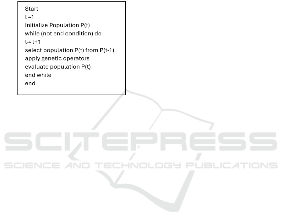
combining characteristics from the parents. The basic
procedure of the genetic algorithm (GA) involves
population initialization, fitness calculation,
selection, crossover, mutation, and the creation of a
new population until a stopping condition is reached
(Faletti Almeida, 2007), as shown in Fig. 3. The
problem representation is done through a set of
parameters encoded in a chromosome, which is
decoded to build the actual solution (individual).
In the GA process, evaluation is essential to assign
everyone in the population a numerical value
corresponding to their ability to solve the problem.
Crossover involves exchanging parts of the
chromosomes of two individuals to generate novel
solutions, while mutation consists of randomly
changing the values of the genes in the chromosomes,
ensuring diversity in the population (Faletti Almeida,
2007). The evolution parameters that affect the
performance of the genetic algorithm include
population size, crossover rate, mutation rate, and
Improving Floating Wind Turbine Stability with Evolutionary Computation for TMD Optimization
477
generation interval. Proper adjustment of these
parameters is essential for efficient search.
Performance evaluation is done through evolution
curves (Fogel et al., 2000). In this study, genetic
algorithms are used to optimize the parameters of the
passive structural control type TMD in barge-type
FOWTs.
Figure 3: Basic procedure of a Genetic Algorithm (Faletti
Almeida, 2007).
2.4 Related Works
FOWTs have been focus of different recent research
efforts aimed at improving system efficiency,
especially through structural control to avoid negative
interference from wind and waves and to control
vibrations. Studies have examined both passive and
active control for floating wind turbines, highlighting
the use of tuned mass damper devices (Chen et al.,
2021). Most of these devices are installed in the
nacelle of the turbines, although some research has
explored installations in the turbine tower and on
barge-type platforms (Chen et al., 2021). The design
of these devices involves optimizing parameters to
reduce vibrations in the FOWT structure. Simulators
such as FAST, developed by NREL, have been used
to evaluate passive TMD control solutions in different
FOWT configurations (Lackner & Rotea, 2011).
Additionally, linear models have been developed to
investigate the effects of vibration suppression under
a variety of load cases (He et al., 2017).
A new passive structural control method for
FOWTs is proposed in (Liao & Wu, 2021), to
overcome previous limitations in TMD space. The
work includes optimizing a TMD installed in the
nacelle, showing that it can significantly reduce
structural loads and stabilize power output. TMD
parameter tuning is currently done through methods
such as frequency tuning, genetic algorithms, and
surface plots. The use of genetic algorithms to
optimize TMD designs has grown, with promising
results in simulations (Lackner & Rotea, 2011).
Although explored the inclusion of stops in TMD
models, the optimization of these parameters is still
limited, often using simplified system models during
the optimization cycle (Costoya et al., 2020).
Furthermore, few studies address the use of TMDs
both fore-aft and lateral-lateral to mitigate structural
fatigue, neglecting stop variables in the optimization
process and employing simplified FOWT models
(Lackner & Rotea, 2011).
This work proposes the optimization of a passive
structural control system with two TMD devices
(fore-aft and lateral-lateral) installed in the nacelle,
incorporating stroke limitation during the
optimization cycle. The performance of these devices
is evaluated under free decay conditions using the
FAST-SC simulator directly in the optimization
process.
3 METHODOLOGY
3.1 Characterization: FOWT and
Barge
This work uses a 5MW floating offshore wind turbine
developed by the National Energy Laboratory
(NREL). With a horizontal axis, three blades and
variable speed, designed for position against the
wind, with a 126m diameter rotor and 90m hub
height, as shown in Table 1. Widely adopted in
research, this model is supported by organizations
such as Union Upwind and the International Energy
Agency, is considered economically viable for
FOWT's due to their size (Jonkman, 2007).
Mounted on a barge developed in partnership by
the Universities of Glasgow and Strathclyde, together
with ITI Energy, the barge is square and ballasted
with seawater, anchored by eight catenary lines
(Vijfhuizen, 2006), as shown in Table 2. For
structural control, we opted for the TMD device,
installed in the nacelle, composed of a mass
connected to springs and shock absorbers, effective in
reducing vibrations. The TMD, vibrating in phase
opposite to the structure, reduces vibrational energy,
converting it into heat. These systems are tuned to the
natural frequency of the structure, generally its first
most relevant vibrational mode in the system's
response (Villoslada et al., 2022).
ICPRAM 2025 - 14th International Conference on Pattern Recognition Applications and Methods
478
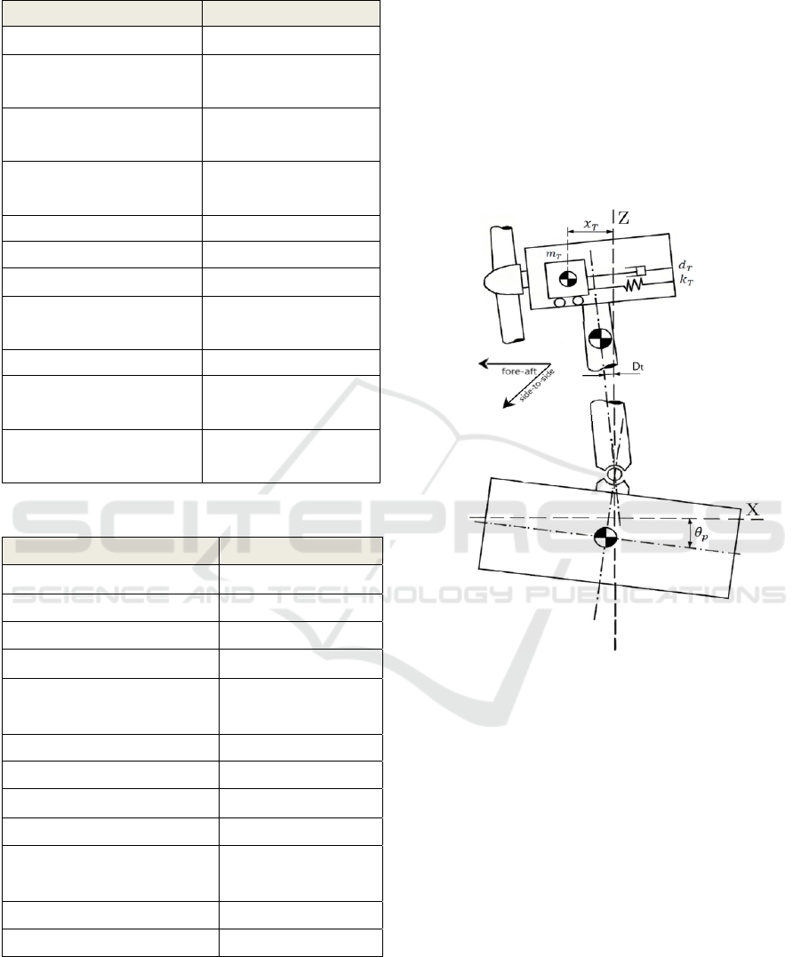
Table 1: FOWT NREL-5MW (Chen et al., 2021).
Parameters Dimensions
Rating 5MW
Rotor Orientation,
Configuration
Upwind, 3 Blades
Control Variable Speed,
Collective Pitch
Drivetrain High Speed, Multiple-
Stage Gearbox
Rotor, Hub Diameter 126m, 3m
Nacelle Dimension 18m x 6m x 6m
Hub Height 90m
Cut-In, Rated, Cut-Out
Wind Speed
3m/s, 11.4m/s, 25 m/s
Cut-In, Rated Rotor Speed 6.9 rpm, 12.1 rpm
Rotor Mass/ Nacelle Mass/
Tower Mass
110tons, 240tons,
347.46tons
Coordinate Location of
Overall CM
(-0.2 m, 0.0 m, 64.0 m)
Table 2: ITI Energy Barge (Vijfhuizen, 2006).
Parameters Dimensions
Size (W × L × H) 40m x 40m x 10m
Moonpool (W × L × H) 10m x 10m x 10m
Draft, Freeboard 4m, 6m
Mass, including Ballast 5,452,000kg
Center of Mass (CM) below
SWL
0.282 m
Roll Inertia about CM 726,900,000 kg⋅m²
Pitch Inertia about CM 726,900,000 kg⋅m²
Yaw Inertia about CM 1,453,900,000 kg⋅m²
Anchor (Water) Depth 150m
Neutral Line Length Resting
on Seabed
250m
Line diameter 0.0809m
Extensional line stiffness 589,000,000 N
3.2 Parametrization of TMD’s
The main parameters of the TMDX (forward-reverse
direction) are: mass mT (kg), where a greater mass
increases inertia and stored kinetic energy, limited by
the total mass of the structure; spring stiffness kT
(N/m); damping dT (N⋅s/m); position xT (m), which
influences design loads and constraints; orientation
(front-back or side, side-side); and travel limits (stops
to limit the movement of the TMDX, affecting loads
and restrictions). The barge model considers platform
compliance, with tower and TMDX degrees of
freedom, in addition to the launch degree. In this
context, the following sub-indices are used: TMDX
(T), tower (t), stops (S) and barge-type platform (p).
The complete TMDX model is illustrated in Fig. 4.
Figure 4: Complete system model for TMDX. Adapted
from (Villoslada et al., 2022).
The TMDX stops, or stops limit the displacement
of the resonant mass, making the installation viable
and realistic. They consist of an additional spring and
a shock absorber that come into action when the mass
deviates a certain distance from the rest position. Stop
parameters include actuation distance (XS), spring
stiffness (kS) and damping coefficient (dS). The
operational logic of the stops follows the same
performance as the FAST simulator, with the spring
always active and the damper only operating when
the mass moves away from the rest position (Fig. 5).
The TMDY, with side-to-side direction, has the
same parameters as the TMDX, but its location is
different, and it is installed to reduce lateral fatigue
on the nacelle. Both are arranged in a "cross" shape in
relation to the center of the nacelle, having different
vertical dimensions.
Improving Floating Wind Turbine Stability with Evolutionary Computation for TMD Optimization
479
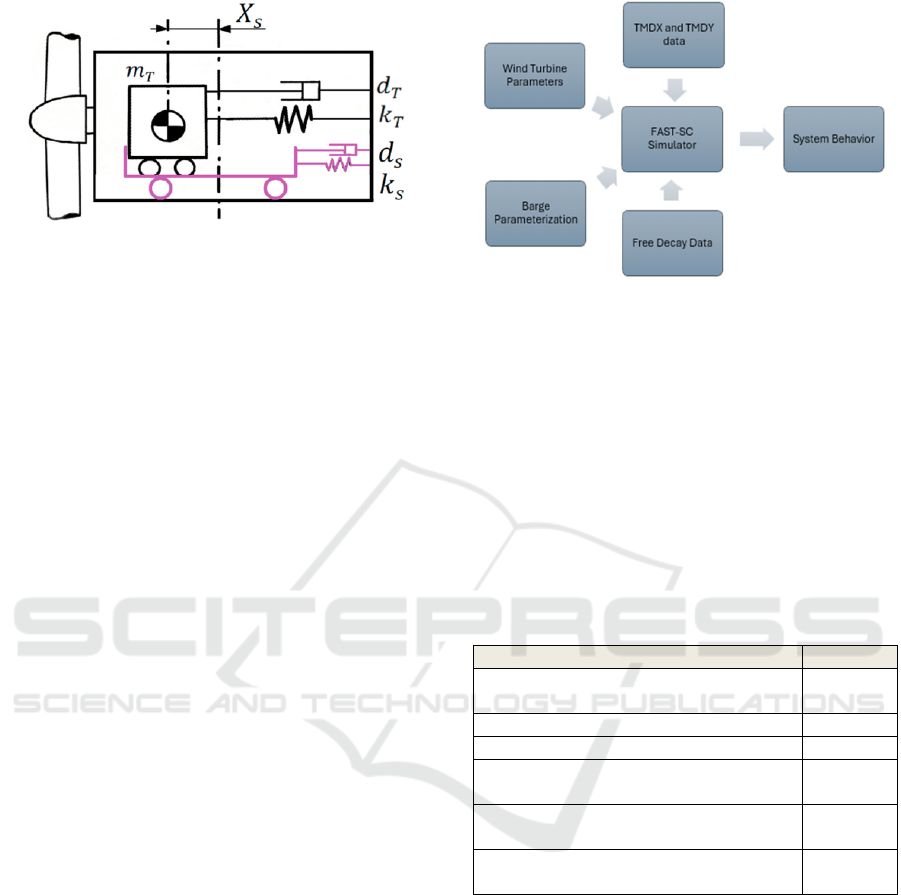
Figure 5: Addition of stops to the TMDX system. Adapted
from (Villoslada et al., 2022).
3.3 FAST-SC Simulator
FAST (Fatigue, Aerodynamics, Structures and
Turbulence) software simulates a 5 MW wind
turbine, using the AeroDyn and HydroDyn modules
to calculate aerodynamics and hydrodynamic loads
on the floating platform. It employs temporal
simulation to solve nonlinear equations, considering
varied factors such as axial and tangential induction,
tip and hub losses, and dynamic stall modeling
(Lackner & Rotea, 2011).
In this simulator, two independent TMDs are
integrated for structural control, this modified version
of the software being called 'FAST-SC'. The
equations of motion are derived using Kane dynamics
(Kane & Levinson, 1985). The TMDs are positioned
in the wind turbine nacelle and consist of mass,
spring, and damper. The position of each TMD,
including the neutral spring position, is defined
relative to the centerline of the top of the tower,
exerting an equal and opposite force on the nacelle.
Each TMD has two stroke limiters to restrict
movement (Kane & Levinson, 1985).
The TMDs oscillate axially in the turbine nacelle
(TMDX) and laterally (TMDY), generating forces. Its
equations of motion, derived from FAST, consider
positions, velocities, accelerations, and forces. In
FAST-SC, TMDX and TMDY are independent and
can be controlled in several ways by the user,
including passive, semi-active, or active control
(Lackner & Rotea, 2011).
The FAST-SC simulator uses an executable file
and a main input file. The latter allows the user to
modify initial parameters to represent the proposed
system, including information about the simulation,
wind turbine, buoyancy base (if applicable) and
TMD’s. It also requires secondary files and libraries
for its proper functioning (Fig. 6).
Figure 6: Simplified FAST-SC flowchart.
In the optimization simulations, simplified system
conditions were used, including free decay of the
structure (wind of 0.5 m/s and without kinematic
wave model). The response to an initial displacement
of 5 degrees in pitch and 10 degrees of initial yaw
rotation on the platform was analyzed. The main
parameters include simulation time (one hundred
seconds), degrees of freedom (DOF’s) of rotation,
pitch, and yaw of the platform, as well as the flexion
modes are set to 'True' and the initial conditions,
shown in Table 3.
Table 3: Main input parameters in FAST.
Parameters Value
RotSpeed (speed rotor initial) 12.1
(rpm)
TmdXDsp (displacement TMDX initial) 1.0 (m)
TmdYDsp (displacement TMDY initial) 1.0 (m)
PtfmRoll (displacement initial rotation
platform)
5 degrees
PtfmPitch (displacement platform initial
step)
5 degrees
PtfmYaw (displacement. platform initial
lurch)
10
degrees
3.4 Genetic Algorithm Parametrization
In this work, MATLAB software was used with its
optimization libraries to encode the genetic
algorithm. During the GA optimization cycle, each
individual goes through a 100-second simulation in
FAST-SC, with free system decay, to analyze their
response in relation to the tower deflection in x and y
(m) and the barge pitch (degrees). These results make
it possible to evaluate everyone’s performance in
reducing structure fatigue. Each individual is
represented by a chromosome with 14 variables, half
of which are for the TMDX parameters and the other
half for the TMDY parameters. Table 4 contains the
ICPRAM 2025 - 14th International Conference on Pattern Recognition Applications and Methods
480
description of each variable and its lower and upper
limits.
The evaluation function (fa), which determines
the fitness of each individual, is based on the
deflection of the tower (in meters) on the x (Dtx) and
y (Dty) axes, with a weighted average being applied
between both. Due to the greatest fatigue occurring in
the x-axis [11], the total standard deviation of the
evaluation function was calculated according to
equation 1.
𝑓
𝑎
𝜎
(
𝐷𝑡𝑥
)
9 𝜎
(
𝐷𝑡𝑦
)
10
(1)
Table 4: Lower and upper limits of optimized parameters.
TMD’s Parameters Low Limit Upper
Limit
TmdXMass (mass) 18,000 kg 42,000 kg
TmdYMass (mass) 8,000 kg 12,000 kg
TmdXSpr, TmdYSpr
(spring stiffness)
103 N/m 105 N/m
TmdXDamp, TmdYDamp
(damping)
1,000
N.s/m
20,000
N.s/m
TmdXDwSp (stop
position - positive axis)
7.5 m 8.3 m
TmdXDwSp (stop
position - negative axis)
-8.3 m -7.5 m
TmdYDwSp (stop
position - positive axis)
1.5 m 2.3 m
TmdYDwSp (stop
position - negative axis)
-2.3 m -1.5 m
TmdXSSpr, TmdYSSpr
(stop spring)
104 N/m 106 N/m
TmdXSDamp,
TmdYSDamp (stop
damping)
104 N.s/m 106 N.s/m
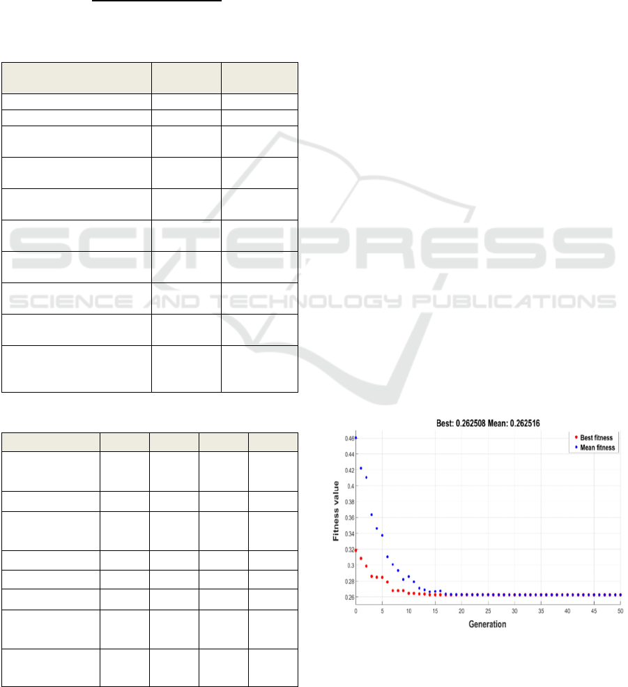
Table 5: Main GA evolution parameters.
Parameters 1º 2º 3º 4º
Prossessing
Number
12 11 3 5
Population 50 50 15 15
Max.
Generations
50 50 30 30
Crossover Rate 0.70 0.70 0.70 0.70
Mutation Rate 0.30 0.30 0.30 0.30
Elitization 5 5 2 3
Stopping
Criteria
10-6 10-6 10-6 10-6
Best Individual
(
𝑓
𝑎)
0,2625 0.2714 0,2731 0,2781
Twenty processing of the genetic algorithm were
done to obtain the best TMD parameterization results.
In Table 5, the main evolution parameters for GA
processing that resulted in the four best results are
presented.
4 RESULTS
The best individual (solution) among the GA
processes was obtained in the 12th process, as shown
in the generation versus evaluation function curve in
Fig. 7. The curve shows that the best individual
reached a value of 0.262508, with an average of
0.262516 per generation.
The graph also shows that GA converged on
satisfactory results from the 17th generation onwards,
demonstrating its effectiveness in identifying the
ideal solution in a relatively short time. This
efficiency is fundamental for studies involving
multiple interdependent variables, such as TMD
parameters, and complex structural analysis
conditions.
The use of GA in this study is justified for several
reasons. Firstly, the problem in question does not
have a defined equation that allows the use of
gradient-based methods, making GA an appropriate
choice due to its ability to explore large solution
spaces without relying on derivatives. In addition, GA
simplifies the mathematical representation of the
system, allowing the optimization process to be
conducted in a more straightforward and intuitive
manner. By operating under free decay conditions
and with reduced degrees of freedom (DOFs), GA can
quickly find the best results for the TMD parameters,
maximizing computational efficiency and reducing
total processing time.
Figure 7: GA behaviour: generations versus evaluation
function.
Improving Floating Wind Turbine Stability with Evolutionary Computation for TMD Optimization
481
These factors demonstrate the robustness and
adaptability of GA as an optimization tool for non-
linear and highly complex systems, such as floating
wind turbines. GA's ability to find optimal solutions
in vast search spaces with multiple constraints
reinforces its relevance for future studies seeking to
optimize structural control devices under different
operating conditions.
The results of the system optimization, with the
best parameterizations for TMDX and TMDY, are
shown in Table 6. The optimization resulted in a
TMDX with a standard deviation of front-to-back
deflection of 0.2511 and a TMDY with a standard
deviation of side-to-side deflection of 0.3655. These
values indicate a significant reduction in the tower's
structural vibrations, directly contributing to reduced
fatigue in the control devices and the overall structure
of the FOWT. This improvement reinforces the
effectiveness of optimized TMDs in mitigating
oscillations in the main axes, extending the useful life
of critical components.
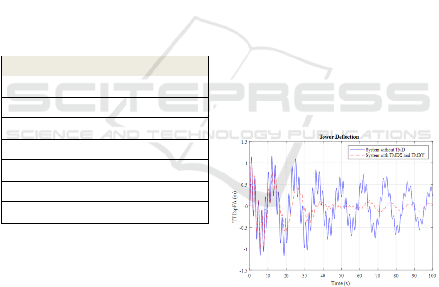
Table 6: Optimized parameters for TMDX and TMDY.
Parameter
s
TMD
X
TMDY
Mass (kg
)
40,07
6
8,93
8
Spring (N/m
)
3,74
6
93,82
4
Damping (N.s/m
)
8,60
7
1,00
6
Stop Position (m
)
± 8.
0
± 2.
2
Stop Spring (N/m
)
10,00
2
129,36
3
Stop Damping (N.s/m
)
389,95
4
85,95
7
𝜎
(tower deflection
)
0.251
1
0.365
5
In addition, Table 6 shows the main optimized
parameters for the TMDX and TMDY devices, which
play important roles in the structural control of the
FOWT. The 40,076 kg mass of the TMDX allows for
greater inertia to reduce front-to-back vibrations,
while the spring stiffness (3,746 N/m) and damping
(8,607 N.s/m) balance the dynamic response. On the
TMDY, the reduced mass of 8,938 kg is suitable for
lateral-lateral control, with higher spring stiffness
(93,824 N/m) and lighter damping (1,006 N.s/m) due
to the different nature of lateral oscillations.
The stop positions (±8.0 m) for TMDX and ±2.2
m for TMDY) and the respective spring and damping
parameters of the stops ensure that the displacement
of the mass is controlled within safe limits, avoiding
overloads on the devices and the structure. These
values, calibrated for the specific conditions of the
FOWT, demonstrate how optimized parameterization
contributes to a more efficient and reliable system.
Figures 8 and 9 highlight a significant
improvement in the system's dynamic response after
the inclusion of the optimized TMDX and TMDY.
Figure 8 illustrates the reduction in the displacement
of the fore-aft tower, while Figure 9 shows the
reduction in the inclination of the barge.
When compared to the system without any TMD,
there is a 36.7% reduction in the root mean square
error (RMSE) of the deflection, showing the
effectiveness of the optimized devices. This reduction
is a clear indication of the mitigation of structural
vibrations, which is essential for extending the useful
life of the FOWT and reducing maintenance costs
associated with structural fatigue. This RMSE value
not only reflects a lower oscillation amplitude, but
also demonstrates how the optimized TMDs manage
to balance the dynamic forces imposed on the system.
This result is visibly highlighted in the graphs,
which show a more uniform and consistent
attenuation of vibrations compared to the original
system. The significant decrease in oscillations
reinforces the importance of incorporating optimized
passive control solutions, such as the TMDX and
TMDY, to improve the stability and operational
reliability of floating wind turbines in real operating
conditions.
Figure 8: Tower deflection - system without TMD versus
system with TMDX and TMDY.
ICPRAM 2025 - 14th International Conference on Pattern Recognition Applications and Methods
482
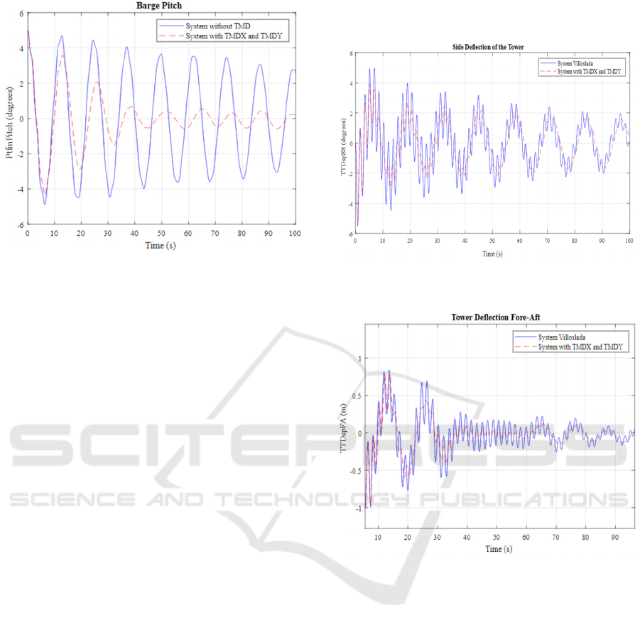
Figure 9: Barge Pitch - system without TMD versus system
with TMDX and TMDY.
For comparison purposes, Figures 10 and 11 show
the graphs of the front-to-back displacement and
lateral displacement of the tower of this system,
compared to the results obtained by Villoslada et al.
(2022), who optimized only the TMDX under similar
initial conditions and free decay.
The analysis shows that the system with
bidirectional TMDs (TMDX and TMDY) performed
11% better in terms of RMSE than the unidirectional
system optimized by Villoslada. This increase in
performance reflects the improved ability of the
bidirectional TMD system to mitigate vibrations in
multiple directions, contributing to a more balanced
reduction in the dynamic forces on the structure.
This superiority of the proposed structural control
system is especially important for floating wind
turbines, which face complex, multi-directional loads
from wind and platform movements. While the
unidirectional TMD system focuses on attenuating
front-to-back oscillations, the use of bidirectional
TMDs allows for a more comprehensive approach,
also reducing lateral oscillations, which are critical
for avoiding structural failures and reducing tower
fatigue.
Figures 10 and 11 visually highlight how the
combination of TMDX and TMDY optimizes the
dynamic response of the tower, resulting in lower
displacement amplitudes in both directions and,
consequently, greater reliability and operational
stability of the system.
There is a significant improvement in the
response of the system that incorporates TMDX and
TMDY compared to the system without any TMD,
achieving a 36.7% reduction in deflection (RMSE:
root mean square error). Furthermore, there was an
11% superior performance (RMSE) compared to the
system developed by Villoslada et al. (2022), which
optimized only TMDX.
Figure 10: Tower deflection - system with TMDX and
TMDY versus results from Villoslada et al. (2022).
Figure 11: Tower Lateral Deflection - system with TMDX
and TMDY versus results from Villoslada et al. (2022).
5 CONCLUSIONS
This study highlights the importance and effectiveness
of passive control in reducing vibrations and pendulum
loads in floating wind systems, making them more
efficient and attractive for energy production. The
main contribution of this work is the comprehensive
consideration of the parameters of the dual TMD
control device in the nacelle, both in the front-to-back
and lateral-to-lateral directions, in the optimization
cycle, demonstrating that the proposed approach
achieves a significant reduction in fatigue (36.7%).
The use of evolutionary computation to
parameterize TMDs is recommended, as the results of
this study reinforce the effectiveness of the genetic
algorithm (GA) as an optimization tool for complex
Improving Floating Wind Turbine Stability with Evolutionary Computation for TMD Optimization
483

systems such as floating wind turbines. From the 17th
generation onwards, GA converged quickly to
satisfactory solutions, demonstrating its ability to
identify the best TMD parameters under free decay
conditions and with reduced degrees of freedom.
In addition, the absence of a defined equation for
the problem justifies the use of GA, which simplifies
the mathematical representation and makes it possible
to explore a wide space of solutions. These factors
highlight the relevance of GA for future applications
in passive structural systems and highly complex
scenarios.
These findings have broad applicability, not
limited to barge-type FOWTs. For example, the
approach can be adapted to other types of floating
platforms, such as Spar Buoys and Tension Leg
Platforms (TLPs), which have different structural
dynamics and operational challenges. In Spar Buoys,
the mass of the TMD could be adjusted to compensate
for the high moment of inertia due to the elongated
structure. In TLPs, TMDs could be used to deal with
the horizontal oscillations generated by the tensioned
anchoring forces.
It is worth noting that the integration of the
proposed methodology into hybrid platforms, which
combine floating elements with fixed foundations,
can be explored, extending its applicability to
different configurations and maritime environments.
Future work could also include simulations and
optimizations under more complex loading
conditions, such as turbulent winds and irregular
waves, as well as considering TMD devices installed
in other parts of the system, such as on the tower or
platform, for an integrated control approach. These
future directions have the potential to broaden the
relevance of the proposed approach and provide more
robust solutions for the next generation of offshore
wind systems.
REFERENCES
Butterfield, S., Musial, W., Jonkman, J., & Sclavounos, P.
(2007). Engineering Challenges for Floating Offshore
Wind Turbines. National Renewable Energy Laboratory.
Chen, X., Kareem, A., Xu, G., Wang, H., Sun, Y., & Hu, L.
(2021). Optimal tuned mass dampers for wind turbines
using a Sigmoid satisfaction function‐based
multiobjective optimization during earthquakes. Wind
Energy, 24(10), 1140–1155.
Costoya, X., deCastro, M., Carvalho, D., & Gómez-
Gesteira, M. (2020). On the suitability of offshore wind
energy resource in the United States of America for the
21st century. Applied Energy, 262, 114537.
Faletti Almeida, L. (2007). Sistema Híbrido de Otimização
de Estratégias de Controle de Válvulas de Poços
Inteligentes sob Incertezas [Doctoral dissertation].
PUC Río.
Figueiredo, A. C. V. S. (2019). Feasibility assessment of
applying a small wind turbine in a guesthouse in
Arraial do Cabo [Doctoral dissertation]. Federal
University of Rio de Janeiro.
Fogel, D. B., Bäck, T., & Michalewicz, Z. (Eds.). (2000).
Evolutionary computation. Institute of Physics
Publishing.
He, E.-M., Hu, Y.-Q., & Zhang, Y. (2017). Optimization
design of tuned mass damper for vibration suppression
of a barge-type offshore floating wind turbine.
Proceedings of the Institution of Mechanical Engineers,
Part M: Journal of Engineering for the Maritime
Environment, 231(1), 302–315.
Hu, Y., & He, E. (2017). Active structural control of a
floating wind turbine with a stroke-limited hybrid mass
damper. Journal of Sound and Vibration, 410, 447–472.
Jonkman, J. M. (2007). Dynamics Modeling and Loads
Analysis of an Offshore Floating Wind Turbine
(NREL/TP-500-41958, 921803; p. NREL/TP-500-
41958, 921803).
Kane, T. R., & Levinson, D. A. (1985). Dynamics, theory
and applications. McGraw-Hill.
Lackner, M. A., & Rotea, M. A. (2011). Passive structural
control of offshore wind turbines. Wind Energy, 14(3),
373–388. https://doi.org/10.1002/we.426
Liao, M., & Wu, Y. (2021). Conceptual design and dynamic
analysis of a novel passive floating offshore wind
turbine structure. Ships and Offshore Structures,
16(10), 1040–1049.
Olondriz, J., Jugo, J., Elorza, I., & and Aron Pujana-Arrese,
S. A.-Q. (2019). A Feedback Control Loop
Optimisation Methodology for Floating Offshore Wind
Turbines. Energies, 12(18), 3490.
https://doi.org/10.3390/en12183490
Picolo, A. P., Rühler, A. J., & Rampinelli, G. A. (2014).
Uma abordagem sobre a energia eólica como
alternativa de ensino de tópicos de física clássica.
Revista Brasileira de Ensino de Física, 36(4), 01–13.
Stewart, G., & Lackner, M. (2013). Offshore Wind Turbine
Load Reduction Employing Optimal Passive Tuned
Mass Damping Systems. IEEE Transactions on Control
Systems Technology, 21(4), 1090–1104.
Stewart, G. M. (2012). Load reduction of floating wind
turbines using tuned mass dampers.
Vijfhuizen, W. J. M. (2006). Design of a wind and wave
power barge [Doctoral dissertation, MS Thesis].
Department of Naval Architecture and Mechanical
Engineering, Universities of Glasgow and Strathclyde.
Villoslada, D., Santos, M., & Tomás-Rodríguez, M. (2022).
TMD stroke limiting influence on barge-type floating
wind turbines. Ocean Engineering, 248, 110781.
Zuo, H., Bi, K., & Hao, H. (2020). A state-of-the-art review
on the vibration mitigation of wind turbines. Renewable
and Sustainable Energy Reviews, 121, 109710.
ICPRAM 2025 - 14th International Conference on Pattern Recognition Applications and Methods
484
