
A Domain Specific Language to Design New Control Architectures for
Smart Grids
Asma Smaoui
1 a
, Mathilde Arnaud
1 b
, St
´
ephane Salmons
1 c
and Guillaume Giraud
2 d
1
Universit
´
e Paris-Saclay, CEA, List, F-91120, Palaiseau, France
2
R
´
eseau de Transport d’
´
Electricit
´
e (RTE), Paris, France
Keywords:
DSML, MBSE, Smart Grid, SysMLv1, SysMLv2, Control System.
Abstract:
Model Based System Engineering is widely used for the development of Cyber Physical Systems and in
particular Smart Grids (SG). SysML/UML are used for several years to develop Domain Specific Modeling
Languages (DSML) each one tackling one or several aspects/viewpoints of the SG. In this Paper we will not
just present yet another DSML for SG control design, but we will discuss different modeling patterns adopted
to define the DSML and discuss the added value/gain of next generation languages/tools mainly SysML v2 and
web tools in the developing of DSML. Our DSML is the first building blocks of a Modeling tool integrated
in the new RTE (French Energy Transmission company) platform to design, simulate and evaluate the new
control architectures of the French electrical transmission network.
1 INTRODUCTION
This paper presents a DSML for Smart Grid control
system. This DSML is the first building blocks of a
modeling tool integrated within the NACRE (Novel
Architecture to Control the Electrical Transmission
Network) platform. NACRE is a new platform to de-
sign, simulate and evaluate control architectures of
the transmission grid. When considering smart grids,
the top-level standard framework is the SGAM (Smart
Grid Architectural Model) (CEN-CENELEC-ETSI,
2012). As shown in Figure 1, the SGAM model cap-
tures all aspects of a smart grid.
Figure 1 defines the scope of the paper by high-
lighting the ”layers”, ”zones” and ”domains” of the
SGAM architectural framework that are relevant for
the NACRE platform. We are considering only
the electricity “Transmission” domain of the SGAM,
even though the “Generation” and “Distribution” do-
mains are closely linked to the transmission domain.
The aim of the NACRE project is not to model the
electricity transmission grid, but rather to model the
control system of this network. It is nevertheless nec-
essary to handle the components of the transmission
a
https://orcid.org/0000-0002-1928-7166
b
https://orcid.org/0000-0001-7953-8281
c
https://orcid.org/0009-0002-0736-3552
d
https://orcid.org/0000-0001-6965-4772
NACRE
scope
Figure 1: Scope of NACRE within the Smart Grid Archi-
tectural Model.
grid (types of substation, sensor, actuator, etc.) with-
out focusing on the internal architecture and operation
of these components. Thus, for the ”Zones” axis, only
Field (contains protection, control and monitoring de-
vices), Station (contains data concentration and func-
tional aggregation modules) and Operation (contains
the Energy Management System (EMS) and distribu-
tion modules) are of interest to the NACRE project, as
shown in Figure 1. Most physical energy conversion
devices are classified in the “Process” zone, which is
outside the scope of the NACRE project. The remain-
196
Smaoui, A., Arnaud, M., Salmons, S. and Giraud, G.
A Domain Specific Language to Design New Control Architectures for Smart Grids.
DOI: 10.5220/0013174800003896
In Proceedings of the 13th International Conference on Model-Based Software and Systems Engineering (MODELSWARD 2025), pages 196-203
ISBN: 978-989-758-729-0; ISSN: 2184-4348
Copyright © 2025 by Paper published under CC license (CC BY-NC-ND 4.0)

ing zones: the “Enterprise” zone for enterprise man-
agement components (logistics, billing, etc.) and the
“Market” zone for market operations (trading, retail,
etc.), are not within the scope of the NACRE project.
For the interoperability layers, all the abstraction lay-
ers are within the scope of the NACRE project, with
the exception of the “Business” layer.
In order to represent various possible architectures
of the control system for the transmission grid, it is
necessary to model these architectures by using a rel-
evant modeling language. The modeling language
must align with MBSE approaches (Douglass, 2016),
widely adopted to develop complex systems (Neure-
iter and Binder, 2022). Among the benefits of the
MBSE approach, we highlight: (1) the description of
a system architecture in a non-monolithic way, as a
coordinated set of views and viewpoints, each focus-
ing on a specific aspect of the system as explained
in the ISO 42010 standard (ISO/IEC/IEEE 4201C0,
2022). (2) The possibility to develop a system archi-
tecture through successive refinement steps (Neure-
iter and Binder, 2022) and (3) the use of domain spe-
cific modeling language (DSML) (Challenger et al.,
2014). In the next section, we will discuss related
works in defining DSML for Smart Grid.
2 RELATED WORKS
The NACRE DSML aims to design the future archi-
tecture of the electricity transmission network con-
trol system. This architecture must be independent
of the tools used later for simulation or development.
The constraints generated by the use of a simulation
tool should not impact the design of this architecture.
These simulation constraints will be processed at the
level of the simulation model which will be automat-
ically generated from the architectural model as far
as possible. Maintaining a traceability link between
the different models of the system is one of the pil-
lars of MBSE. This will ensure that the final system
will meet the requirements identified at the highest
level of the development cycle. Thus, unlike sim-
ulation models (that are platform specific models),
the NACRE DSML is at a higher level of abstraction
than a simulation language. PowSyBl (Power System
Blocks) (LFEnergy, 2024) is an open source library,
dedicated to electrical grid modeling, simulation and
visualisation. IIDM (iTesla Internal Data Model) pro-
vides an object-oriented model of the power grid.
PowSyBl/IIDM formally establish both physical and
electrical data models. As stated in (Zhou and Feng,
2020), there are three main types of grid online anal-
ysis data models: 1) physical (Node/Breaker) data
model; 2) Bus/Breaker data model; 3) simulation
(Bus/Branch) data model. The PowSyBl design scope
(the power grid topology physical model) is different
from the NACRE DSML design scope (the Control
Architecture of the power grid). However, a model
to model transformation is possible from IIDM to
the NACRE DSML in order to import if relevant the
power grid topology. In (Nasraoui et al., 2017), au-
thors propose a DSML to design the distribution net-
work. The DSML proposed in (Mori et al., 2018)
is targeted towards a more general System of Sys-
tems. As the NACRE DSML scope is the transmis-
sion network, these works do not apply to our spe-
cific aim. SysML (OMG, 2019a) has been widely
used in MBSE of complex systems including smart
Grid. However, as a generic modeling language,
SysML should be customized to manipulate concrete,
domain-specific concepts. Recent works are using
the latest version of SysML (OMG, 2024) to design
DSML such as (Delsing et al., 2022) and (Hristo-
zov and Matson, 2024) for the SOA (Service ori-
ented architecture) design and (Li et al., 2024) for a
collaborative designs in the automotive domain. For
the NACRE DSML, we also rely on MARTE (OMG,
2019b), another OMG standard language for real time
and embedded systems design. Several works are
combining MARTE and SysML such as (Huang et al.,
2018) and (H. Espinoza and S.Gerard, 2009) but none
have the same scope as the NACRE DSML: design
the control architecture of a power grid model com-
bining both control and telecommunication views.
3 NACRE DSML MODELING
PATTERNS
In this section, we discuss the main modeling
choices made while defining the NACRE DSML. The
NACRE DSML concerns 2 different point of views
”ViewPoints” according to (ISO/IEC/IEEE 4201C0,
2022): the Control view (to design the control archi-
tecture of the Power Grid) and the telecommunica-
tion view (to design the communication between the
controllers). Thus, the modeling aspect of the electri-
cal transmission network (type of nodes, characteris-
tics of each node, behavior of each node, etc.) will
be approached in a coarse-grained way: i.e. network
nodes will be considered as black boxes, and the most
generic concept describing them will be used : only
properties of interest from the “Control” point of view
are useful. Four modeling patterns will be discussed
in this paper: (1) the control levels of the Power Grid,
(2) the communication between Controllers, (3) the
resources control model and its relationship with the
A Domain Specific Language to Design New Control Architectures for Smart Grids
197

Main Grid
Central Controller (CC)
Bus
id: Integer
nominalLevel: VoltageLevel
isConnected: Boolean
Zone
Zone Controller (ZC)
Local Controller (LC)
Substation
«HWSensor»
Sensor
«HWActuator»
Actuator
Equipment
p: NFP_Power
q: NFP_Power
isConnected: Boolean
Battery
maxPowerInjection: NFP_Power
capacity: NFP_Energy
producedEnergy: NFP_Energy
consumedEnergy: NFP_Energy
Generator
v: NFP_Voltage
maxPowerGeneration: NFP_Power
producedEnergy: NFP_Energy
RTE_Installation
v : NFP_Voltage
1
*
1
1..*
0..1
*
1
1
*
*
*
1
*
1
*
*
1
*
1
*
*
*
*
*
1
1..*
1
1..*
*
1
1
1
Figure 2: Main concepts of the NACRE language.
functional control model and (4) the communication
network and its relationship with the control level.
Before detailing each modeling pattern, next subsec-
tion presents the main concepts of the power grid con-
trol for the NACRE DSML.
3.1 Main Concepts
Figure 2 shows the first design using a SysML Block
Definition Diagram. We classified the concepts as
grid structure concepts (blue classes) and control con-
cepts (red classes).
Grid Structure Concepts: The MainGrid is the top
level concept which represents the power grid. It can
be associated with a set of Substations and/or a set
of Zones. A Zone represents a group of substations
that are geographically close and connected by elec-
trical lines. A Substation represents a geographical
node and shall be associated with at least one Bus (an
electrical node of the power grid). Each Bus has a
unique voltage level. An Equipment represents any
type of electronics device connected to the grid such
as (Generator) and (Battery). Hence an Equipment is
necessarily associated with a Bus which represents its
electrical connection to the grid. RTE Installation is
a special type of Equipment that represents the con-
nection of a power line to a Bus.
Controller Concepts: A Controller represents any
type of control device connected to the telecommu-
nication network (not modeled at his level) equipped
with the capability to send commands or measure-
ments to, and receive them from, another controller.
Three levels of power grid control are identified: (1) a
CentralController shall be associated with the Main-
Grid: it represents control at the national level, for ex-
ample: taking charge of the global vision and forecast
calculations, (2) a ZonalController shall be associated
with a Zone: it represents control over all the Sub-
Figure 3: Control pattern for functional control architecture.
stations of the Zone, for example : strategy to avoid
congestion, and (3) a LocalController shall be asso-
ciated with Equipment: it represents control over an
Equipment, for example: strategy for immediate pro-
tective action (such as opening circuit breakers when
a short-circuit is detected).
3.2 Modeling Pattern for Control Levels
To design the control architecture of the electricity
grid, taking into account the three different levels of
control associated to different concepts in the grid
(CC/MainGrid, ZC/Zone and LC/Equipment), several
patterns can be applied. One such pattern is to define
an abstract generic concept ”Controller”, as illustrated
in Figure 3. This generic ”Controller” defines all
common attributes of the control function, e.g. ”con-
trolBehavior” defines the algorithm to be executed
when the control is activated. A more generic pattern
could be proposed to generalize this pattern for any
number of control layers. For example, if a fourth
control level such as a regional level was added. This
first design level is only a functional level, e.g. we
do not define how this Control function will be im-
plemented, which - hardware or software - execution
platform will execute it... This design level is called
the CFA : Control Function Architecture, in contrast
to the CRA : Control Resources Architecture.
3.3 Modeling Pattern for the
Communication Between
Controllers
In SysML, one possible pattern to model the commu-
nication between two Parts involves the use of “Ports”
on both sides of a “connector”. Ports can be typed
by Interfaces, known in SysML as “InterfaceBlock”,
which are special types of block that define proper-
ties and operations, but have no internal structure or
behavior. These SysML concepts ”Part”, “Connec-
tor”, “Port” and “InterfaceBlock” are part of the first
communication pattern between controllers. Figure 4
MODELSWARD 2025 - 13th International Conference on Model-Based Software and Systems Engineering
198

Figure 4: Communication modeling Pattern.
presents a design using this pattern for the commu-
nication between an LC and its Actuator and Sensor.
The generator transmits the “generatedPower” value
through its sensor to the LC. The latter will be able to
send a generation limitation order “curtailment order”
to the generator through its actuator that will execute
the order. Ports have directions to specify the direc-
tion of the flow of information conveyed in the con-
nector. However, this communication pattern is ap-
plied in the same way for all communications between
ZC and LC. Due to the high number of busses in the
power grid (more than 6000 busses for the French
power grid) and the different kinds of equipment in
the same bus, designing such fine grained communi-
cation for each ZC/LC does not scale. Thus, the com-
munication between controllers will be inferred by the
design of the Control Resources Architecture CRA.
3.4 Modeling Pattern for the Resources
Model
The telecommunication viewpoint should be designed
using more specific concepts such as communica-
tion network, computing resources and software re-
sources. All these concepts are defined in MARTE
(Figure 5). However, we should define the relevant
abstraction level of each concept. For instance, We
emphasize the following properties of the telecom-
munications network: latency and throughput. By
studying the different modeling levels of the com-
munication network in MARTE, we chose to use
the “CommunicationMedia” stereotype (Figure 6 (a))
since it includes the already mentioned properties.
The “GaCommHost” stereotype (Figure 6 (c)) con-
tains other properties inherited from the “Scheduler”
resource not relevant to the NACRE DSML. Simi-
larly, the current modeling of the communication plat-
form is at the generic level (GRM). Indeed, a telecom-
munication network can be modeled at the software
level using the “MessageComResource” stereotype
(B. Selic, 2013) (Figure 6 (b)). In MARTE the ex-
ecution platform can be modeled at different levels
of abstraction.For example the controllers (ZC, LC
and CC) are refined to software resources that will
be deployed on computing resources (e.g. virtual
machines, dockers, data centers). For the NACRE
DSML, we chose ”SwSchedubaleResource” to de-
sign software resources and ”ComputingResource” to
design real machines. Although the SysML v1 lan-
guage proposes an ”Allocation” package, the more
detailed ”Allocation” package in MARTE is used
since our ”AllocationEnds” are already MARTE con-
cepts: a ”SoftwareResource” is allocated to a ”Com-
putingResource” that is connected to a ”Communica-
tionMedia” (Figure 7). Once CFA and CRA designs
are done, the last modeling pattern is the CFRA which
consists in linking the functional concepts to the re-
source concepts. For instance, a functional controller
(a ZC for example) can be refined in the resources
platform by a SoftwareResource. This is designed us-
ing the UML ”abstraction” concept. The supplier is
the functional concept and the client is a platform re-
source concept (a software resource). Figure 8 shows
an example of this pattern. A particular attention must
be paid to the modelling of communications in the
CFA, CRA, CRFA hierarchy. According to common
patterns (Martin, 2000), every specialization should
depend on an abstraction. But this is not the case for
”CommunicationMedia” that does not specialise any
CFA abstraction. We made this choice because the
main use of the platform is to study existing concrete
communication infrastructures, it would be very cum-
bersome to infer any abstraction for each study.
3.5 Modeling Pattern for the
Distributed and Centralized Control
Architecture
The aim of the NACRE DSML is to design differ-
ent control architectures of the Power Grid in order to
evaluate them. Two kinds of control architectures are
identified: The Centralized one, where all the control
algorithms are hosted on the same resource (for ex-
ample a Data Center) and the Decentralized control
architecture where each control algorithm is executed
on a different platform resource (for example a local
computing resource). It is then very easy for the end
user to move from one control architecture to another
: the user has simply to reorient the ”Allocation” link
between the ”SoftwareResource” and the ”Computin-
gResource” of each controller as shown in Figure 9.
A Domain Specific Language to Design New Control Architectures for Smart Grids
199
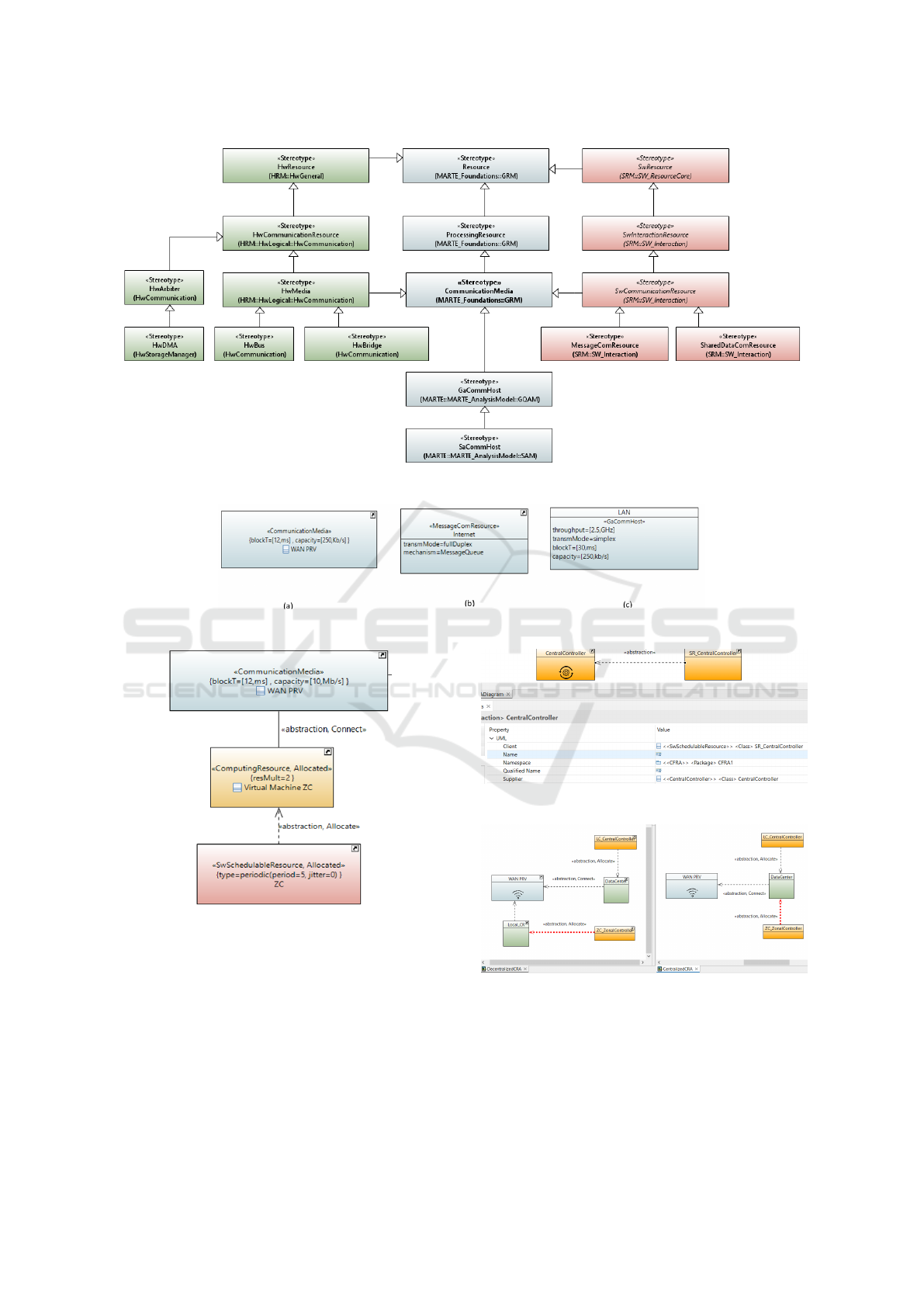
Figure 5: Main concepts of the MARTE language relevant to the NACRE DSML.
Figure 6: Different pattern to design a communication Media in MARTE.
Figure 7: Pattern to ”allocate” SR to CR connected to a CM.
4 TOWARD NEXT-GENERATION
SYSTEMS MODELING
The graphical form of a DSML has several advan-
tages such as the possibility of sharing the model with
non-experts and the serialization in machine readable
format to perform analysis. Yet, despite these advan-
tages, the technologies on which this graphic forms
Figure 8: A snippet of a CFRA diagram.
Figure 9: Centralized (right) vs Decentralized (left) CRAs.
is based for the majority of MBSE tool especially
those based on Eclipse, are not very advanced. For
the NACRE DSML, we were particularly confronted
with scalability issue: How to represent 100 zones in
the same CFA diagram ? How to ensure a good auto-
matic layout that organizes the CRA diagram ? The
MODELSWARD 2025 - 13th International Conference on Model-Based Software and Systems Engineering
200
new generation of modeling languages and in particu-
lar SysML v2 as well as the web-based modeling tools
can solve these problems.
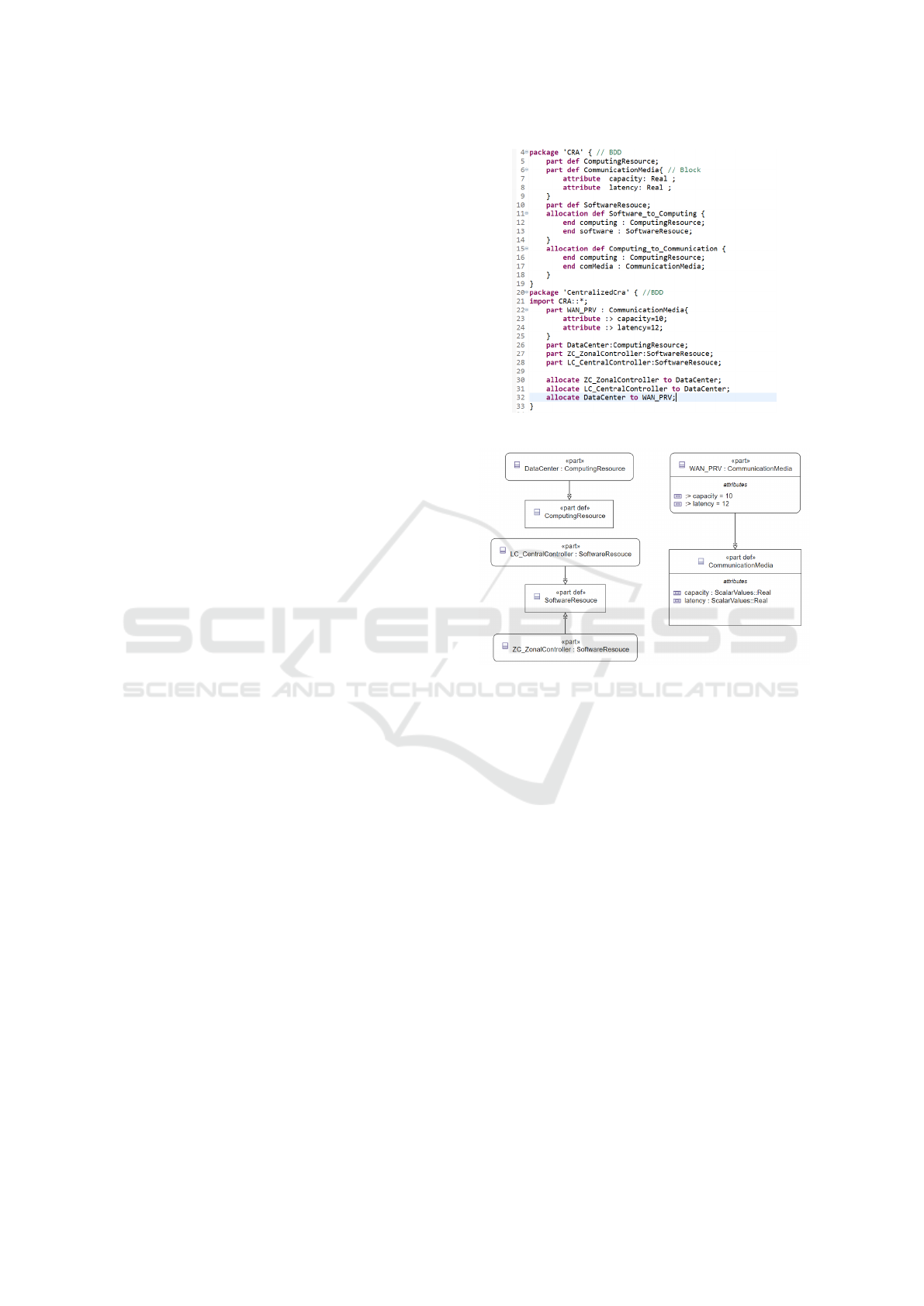
4.1 SysML v2 Standard
SysML v2 is intended to improve SysML v1. A
major change when modeling with SysML v2 is the
introduction of a textual syntax. The textual syn-
tax includes an expression language to represent log-
ical expressions that enable formal solvers to inter-
pret SysML v2 models. The textual syntax can also
be used to exchange models. At the same time,
the graphical syntax is useful to create architectural
views of a system. For the NACRE DSML, the
graphical view is essential mainly for the CRA dia-
gram. Several MBSE companies already support the
SysML v2 language. However, the most advanced
and easy to test implementations are the OMG pilot
implementation (Systems-Modeling, 2024) and the
SysON project implementation. Both of them are
open source. A list of under development SysML v2
tools is available here: (Weilkiens, 2024).
OMG Pilot Implementation. The OMG pilot im-
plementation is the most advanced SysML v2 imple-
mentation. Apart from providing both the textual and
graphical notations, it offers several examples and li-
braries, very useful to get acquainted with the lan-
guage. However, the main drawback of this imple-
mentation is the graphical representation based on
the static PlantUML representation (the user can not
move or resize the graphical elements). To overcome
this drawback, SysON Project based on web tech-
nologies provides a more interactive graphical view of
the SysML v2 language. Figure 10 presents The cen-
tralized CRA diagram of Figure 9 implemented using
the OMG pilot implementation.
SysON Implementation. The Eclipse SysON
project aims to include a different set of editors
(graphical, textual, form-based, etc). Both SysON
and Papyrus Web (CEA, 2024) are based on Sirius, an
open-source low-code platform to define custom web
applications. SysON provides an import functionality
that allows the user to directly import (*.sysml) file.
We have tested this capability. The nacre.sysml
file built by the OMG Pilot Implementation and
presented in 10 was successfully uploaded in SysON.
The result of the SysON graphical representation is
show in Figure 11. We can notice that the allocation
are not well supported in the graphical representation
of SysON, a still under development tool. SysON
implements only the SysML v2 language, however
Figure 10: Centralized CRA in SysML v2 textual notation.
Figure 11: SysON graphical view of Fig 10.
Papyrus web is a more generic tool that implements
the UML2 language and the Profile mechanism that
enable users to define as many DSMLs as they want.
Discussion: Next Generation of the NACRE
DSML. SysOn, being a web tool, offers the same
advantages as Papyrus Web. The user experience
is enhanced using web tools (easy to install, bet-
ter integrated layout, more fluidity in the user in-
terface...). Moreover, SysON will benefit from the
advantages of SysML v2 compared with SysML v1
(Sanford Friedenthal, 2003),(Jansen et al., 2022).
However Papyrus Web will benefit from the exist-
ing NACRE Profile that can be reused as-is. De-
spite the advantages of SysML v2, it depends on the
DSML concepts to decide if it is better to use the
SysML v2 extension mechanisms (metadata, special-
ization) to define updated version for the NACRE
DSML or to keep UML2 profile extension mecha-
nism. It is clear that for software systems, UML is
more convenient (no need for Part, Individual, Snap-
shot concepts which are system oriented). However,
for cyber-physical systems (where compositions be-
A Domain Specific Language to Design New Control Architectures for Smart Grids
201

tween parts, functions designs and constraints evalua-
tion are needed), SysML v2 is more convenient. Nev-
ertheless, Even the Textual syntax of SysML v2, de-
spite its formal specification, presents some ambigui-
ties for the end user. For instance, ”Subclassification”
and ”Subsetting” may be confused with each other be-
cause they use the same symbol. SysML v2 simpli-
fies other SysML v1 concepts such as Ports: Ports in
SysML v2 are equivalent to SysML v1 proxy ports.
Different kinds of SysML v1 Ports (Proxy,Full and
UML Ports) make it difficult to use. The clear separa-
tion between Definitions and Usages and Part special-
isation Usage make SysML v2 more straightforward
than SysML v1.
5 NACRE PLATFORM
The aim of the NACRE platform is to model possible
configurations of the transmission grid control system
using the DSML presented previously in order to sim-
ulate the behaviour of this control system in various
situations. Moreover, the NACRE platform has been
developed to model and simulate communication haz-
ards: that’s why a telecommunication viewpoint was
designed in the CRA as shown in Figure 6.
5.1 Components Description
The NACRE platform is structured in two layers.
Upper Layer: Modeling and User Interface. The
upper layer is composed of 2 modules: the Modeler
module is a customization of Papyrus which offers ad-
vanced edition and display functions for the NACRE
DSML in particular the creation of CFA, CRA and
CFRA models and the Simulation Manager module
(SimMgr) a web interface which allows to configure
a single simulation or a simulation campaign, to con-
trol its execution and to display its results.
Lower Layer: Simulation and Computation. The
lower layer is responsible for simulating the commu-
nication and physical aspects of the situation defined
in the upper layer. It is entirely implemented in Mat-
lab and contains 4 modules : (1) The Control Simu-
lator (ControlSim) module is responsible for config-
uring and executing controllers behaviours. (2) The
Communication Simulator module (CommSim) is re-
sponsible for simulating communication among con-
trollers and their associated hazards. (3) The Physics
Simulator (PhysSim) module is responsible for com-
puting the physical quantities needed to build the
physical state of the power grid. It relies on the Mat-
power library (Zimmerman et al., 2011). (4) The
Simulation Orchestrator (SimOrch) is responsible for
WAN OPR
WAN PRV
cRPT
CR_1445
CR_4720
CR_2745
CR_2135
CR_2075
CR_Batt_10000
Interconexion
LC_2745
LC_4720
LC_Gen_10000
LC_1445
LC_2135
LC_Batt_10000
LC_2075
CR_Gen_10000
ZC
Figure 12: An extract from the CRA model of VGSmall.
maintaining the causal relationships between events
and provides a global date to the different simulators.
5.2 Example of Use
The platform has been tested on several uses cases,
we describe here a simple one due to confidential-
ity and space issues. It is worth to note that the fo-
cus of this paper is to present the DSML and its use.
The lower layer of the platform is presented and dis-
cussed in this paper (Arnaud et al., ). Incoming works
will present more interesting situation with hazards
applied to CRA modeling elements. The zone mod-
elled in this example contains 6 substations, each sub-
station containing one with equipment. Each equip-
ment is locally controlled by a LocalController de-
signed in the CRA (Control Resources Architecture)
model using the MARTE stereotype ”SwSchedula-
bleResource”. Figure 12 shows a CRA diagram for
this zone. Controller software resources (in orange,
LC
id
) are allocated to computing resources (green
components, CR
id
) that are connected to networks
(blue components). In this specific CRA, the zonal
controller ZC is allocated to one of the several com-
puting resources available in the substation of the bus
2135. this substation is connected to the private wan
WAN PRV Communication Media. All generators lo-
cal controllers are allocated to substations connected
to the cRPT client network. This CRA has been sim-
ulated by the NACRE platform to evaluate the behav-
ior of the Zonal Controller (Arnaud et al., ). Other
CRAs can be designed and evaluated by simulation to
choose the most convenient CRA according to differ-
ent criteria such as dependability and robustness.
6 CONCLUSION-PERSPECTIVES
In this paper, we have presented the NACRE DSML
to design the new control architecture of the French
Power Grid. Three layers of control are defined : the
Central, the Zonal and the Local Controls. Three lev-
els of refinement are addressed : the Functional Con-
trol Architecture (CFA), the Resource Control Ar-
chitecture (CRA) and the allocation of resource ele-
ments on the functional elements (CFRA). The cur-
MODELSWARD 2025 - 13th International Conference on Model-Based Software and Systems Engineering
202

rent DSML is implemented using the UML Profile
techniques inspired from SysML v1 and MARTE
OMG standards. We have discussed the migration of
the DSML to SysML v2. The MBSE tools already
suffer from adoption problems due to the complex-
ity of the modeling languages syntax and semantic.
With the new graphical syntax of SysML v2, the user
risks to be faced to a learning barrier that can gener-
ate resistance to adopt the language. For the NACRE
DSML specific needs, a migration to SysML v2 is in-
teresting if Web based tools become available to take
advantages of a fluid UX. However, since Ports, Re-
quirements and behaviour concepts (State machines
and Activities) are (currently) out of scope of the
NACRE DSML, the benefits of moving now from
UML Profiles to SysML v2 appear limited. Indeed,
the platform has been successfully used by RTE to
study different control system configurations.
ACKNOWLEDGEMENTS
We thank Arnault Lapitre, Patrick Tessier, Yves
Lhuillier, Rouwaida Abdallah, Arnaud Guerrier, Do-
rane Sejean and Patrick Panciatici for their extensive
and insightful feedbacks and helps.
REFERENCES
Arnaud, M., Lapitre, A., Lhuillier, Y., Salmons, S., Smaoui,
A., Giraud, G., and Guerrier, A. Modeling and simu-
lating new power grid control architectures. In ISGT
Europe 2023 Innovative Smart Grid Technologies.
B. Selic, S. (2013). Modeling and Analysis of Real-Time
and Embedded Systems with UML and MARTE De-
veloping Cyber-Physical Systems. Elsevier Science.
CEA (Accessed: 2024). Papyrus web. https://gitlab.eclipse.
org/eclipse/papyrus/org.eclipse.papyrus-web.
CEN-CENELEC-ETSI (2012). Smart grid reference ar-
chitecture. https://energy.ec.europa.eu/system/files/
2014-11/xpert group1 reference architecture 0.pdf.
Challenger, M., Demirkol, S., Getir, S., Mernik, M., Kar-
das, G., and Kosar, T. (2014). On the use of a domain-
specific modeling language in the development of
multiagent systems. Engineering Applications of Ar-
tificial Intelligence, 28:111–141.
Delsing, J., Kulcs
´
ar, G., and Haugen, O. (2022). Sysml
modeling of service-oriented system-of-system. Inno-
vations in Systems and Software Engineering, 20(2).
Douglass, B. P. (2016). What Is Model-Based Systems En-
gineering?, chapter 1. Agile Systems Engineering.
H. Espinoza, D. Cancila, B. S. and S.Gerard (2009). Chal-
lenges in combining sysml and marte for model-based
design of embedded systems. In Model Driven Ar-
chitecture - Foundations and Applications, pages 98–
113. Springer Berlin Heidelberg.
Hristozov, A. D. and Matson, E. T. (2024). Modeling as-
pects of dynamically reconfigurable system of sys-
tems. In Verma, D., Madni, A. M., Hoffenson, S., and
Xiao, L., editors, The Proceedings 2023 Conference
on Systems Engineering Research, pages 141–158.
Huang, P., Jiang, K., Guan, C., and Du, D. (2018).
Towards modeling cyber-physical systems with
sysml/marte/pccsl. In COMPSAC 2018.
ISO/IEC/IEEE 4201C0 (2022). Software, systems and en-
terprise — Architecture description. (https://www.iso.
org/standard/74393.html).
Jansen, N., Pfeiffer, J., Rumpe, B., Schmalzing, D., and
Wortmann, A. (2022). The language of sysml v2
under the magnifying glass. J. Object Technol.,
21(3):3:1–15.
LFEnergy (Accessed: 2024). Powsybl. https://www.
powsybl.org/.
Li, Z., Faheem, F., and Husung, S. (2024). Collabora-
tive model-based systems engineering using datas-
paces and sysml v2. Systems, 12(1).
Martin, R. C. (2000). Design principles and design patterns.
Technical report, www.objectmentor.com.
Mori, M., Ceccarelli, A., Lollini, P., Fr
¨
omel, B., Bran-
cati, F., and Bondavalli, A. (2018). Systems-of-
systems modeling using a comprehensive viewpoint-
based sysml profile. Journal of Software: Evolution
and Process.
Nasraoui, K., Lakhoua, N., and Amraoui, L. E. (2017).
Study and analysis of micro smart grid using the mod-
eling language sysml. In GECS.
Neureiter, C. and Binder, C. (2022). A domain-specific,
model based systems engineering approach for cyber-
physical systems. Systems, 10(2).
OMG (2019a). OMG Systems Modeling Language (OMG
SysML™). OMG Doc Nb formal/19-11-01,(https://
www.omg.org/spec/SysML/1.6).
OMG (2019b). UML Profile for MARTE: Modeling
and Analysis of Real-Time Embedded Systems Ver-
sion 1.2. OMG Document Number formal/19-04-
01,(https://www.omg.org/spec/MARTE/1.2/PDF).
OMG (2024). OMG Systems Modeling Language™
(SysML®) Version 2.0 Beta 2. https://www.omg.org/
spec/SysML/2.0/Beta2/Language/PDF.
Sanford Friedenthal, E. S. (2003). Sysml v2: High-
lighting the differences with sysml v1. Technical
report, https://www.ppi-int.com/systems-engineering-
newsjournal/ppi-syen-123/ edition 123.
Systems-Modeling (Accessed: 2024). Sysml-v2-release:
The latest incremental release of sysml v2. https:
//github.com/Systems-Modeling/SysML-v2-Release.
Weilkiens, T. (Accessed: 2024). Sysml v2 mod-
eling tools. https://mbse4u.com/2022/03/09/
sysml-v2-modeling-tools/.
Zhou, M. and Feng, D. (2020). A new modeling approach
for power grid online analysis. IFAC-PapersOnLine,
53(2):13131–13136. 21st IFAC World Congress.
Zimmerman, R. D., Murillo-S
´
anchez, C. E., and Thomas,
R. J. (2011). Matpower: Steady-state operations, plan-
ning, and analysis tools for power systems research
and education. IEEE Transactions on Power Systems,
26(1):12–19.
A Domain Specific Language to Design New Control Architectures for Smart Grids
203
