
Automatic Transcription and Detection of the MTM-1 Hand Motions
Performed in Virtual Reality
Valentina Gorobets
a
, Roman Billeter and Andreas Kunz
b
Institute for Machine Tools and Manufacturing, Swiss Federal Institute of Technology Zurich,
Clausiusstrasse 33, Zurich, Switzerland
{gorobets, kunz}@iwf.mavt.ethz.ch
Keywords:
Virtual Reality, Gesture Transcription, Predetermined Motion Systems, Methods-Time Measurement.
Abstract:
Methods-Time Measurement (MTM) is a predetermined time system that allows analyzing manual work pro-
cesses by dividing performed motions into predetermined basic motions. We present an automatic transcrip-
tion of hand and arm motions in Virtual Reality (VR) using the MTM-1 system. We describe two decision
trees that deliver information about hand and arm motions when handling a virtual object (VO). Additionally,
we discuss the DBSCAN algorithm to transcribe the rest of the arm motions that do not interact with VOs. The
results of an automatic transcription are presented and compared to the ground truth obtained from a manual
transcription. Finally, we discuss the results and further improvements of the algorithm.
1 INTRODUCTION
Virtual Reality (VR) has become more and more ac-
cessible to end users as well as for industrial purposes
in general. Currently, VR is primarily used in the in-
dustrial sector for visualization. However, VR is not
limited to visualization only; it also allows interac-
tions, data recording, and automatic analysis of the
actions performed in VR. A VR setup usually con-
sists of a head-mounted display (HMD) for the visu-
alization of the Virtual Environment (VE), and con-
trollers for the interaction with the intractable Virtual
Objects (VOs) in the VE. Both, HMD and controllers,
are tracked and show the position of the user’s head
and hands in VE. To expand the tracking capabili-
ties, it is possible to use additional trackers that can
be placed either on the human body or real objects.
1.1 Predetermined Time System:
Methods-Time Measurement
Predetermined time systems (PTS) are methods used
in industry to estimate standard times for performing
specific manual tasks or operations. Some examples
of such systems include Methods-Time Measurement
(MTM), Work Factor (WF), MODAPTS (Modular
Arrangement of Predetermined Time Standards), and
a
https://orcid.org/0000-0002-8615-5972
b
https://orcid.org/0000-0002-6495-4327
MOST (Maynard Operation Sequence Technique).
These systems are used to improve productivity, en-
sure consistency in time estimates, and provide a basis
for setting labor standards and improving work meth-
ods. In our work, we present an approach based on
the MTM system, which will be further elaborated.
MTM was first proposed by (Maynard et al.,
1948), which is referred to as MTM-1. It consists of
a set of basic motions and the corresponding TMU
values. The list of MTM-1 motions grouped by body
parts is shown in Table 1. MTM-1 is the most de-
tailed system from all MTM systems. MTM includes
MTM-1, MTM-2, MTM-3, MTM-MEK, and MTM-
UAS systems that differ by their granularity and set
of basic motions defined for each of them.
1.2 Standard MTM Procedure
Experts conduct an MTM analysis by observing mo-
tions performed by the worker. Often, multiple ex-
perts conduct this analysis to avoid errors. They then
subdivide the performed motions into basic motions.
Using MTM tables, they assign predefined time val-
ues to each basic motion and calculate the total TMU
(Time Measurement Units) value required for com-
pleting the task. Finally, MTM experts analyze the
task for efficiency and suggest improvements to opti-
mize performance.
The documentation of the MTM basic motions is
a list of MTM codes that includes a letter abbrevia-
596
Gorobets, V., Billeter, R. and Kunz, A.
Automatic Transcription and Detection of the MTM-1 Hand Motions Performed in Vir tual Reality.
DOI: 10.5220/0013180500003912
Paper published under CC license (CC BY-NC-ND 4.0)
In Proceedings of the 20th International Joint Conference on Computer Vision, Imaging and Computer Graphics Theory and Applications (VISIGRAPP 2025) - Volume 1: GRAPP, HUCAPP
and IVAPP, pages 596-603
ISBN: 978-989-758-728-3; ISSN: 2184-4321
Proceedings Copyright © 2025 by SCITEPRESS – Science and Technology Publications, Lda.

tion of the basic motion, followed by another letter or
number that further specifies it (see Tables 2 and 3).
For example, if a worker gets a small object that is
located 30 cm and then puts it 15 cm away, the tran-
scribed MTM actions are: RB30, G1B, MB15, RL1.
This procedure is costly and time-inefficient, es-
pecially for the MTM-1. It requires manual observa-
tion of the process, as well as an available existing
workplace for the analysis. Therefore, it makes it dif-
ficult to use the MTM analysis during the planning
stage of the processes and workplaces.
2 RELATED WORK
To verify the feasibility of using MTM systems in
VR, research by (Gorobets et al., 2021) compared
two identical setups in VR and reality. They showed
that the TMU values obtained by the MTM-2 sys-
tem were the same for VR and real setup. (Fantoni
et al., 2020) showed approaches to tackle the problem
of the manual nature of an MTM analysis. They use
sensors to gather positions, together with the camera-
based approach. However, research in the area of au-
tomatic transcription of MTM basic motions is still
rare. (Bellarbi et al., 2019) proposed an approach to
detect MTM-UAS basic motions, using a VR headset
and two controllers. An approach to deliver MTM-2
analysis in VR was proposed by (Andreopoulos et al.,
2024). It uses an HMD and controllers, and three
HTC Vive trackers to track the lower back and both
feet. Unlike the MTM-UAS, MTM-2 considers the
number of steps. Additional motions are included
in MTM-2, such as foot motion. An approach to
transcribe basic MTM-1 motions in VR is suggested
by (Gorobets et al., 2024). They transcribe MTM-
1 body motions but don’t explicitly elaborate on the
transcription of the MTM-1 hand and arm motions.
2.1 Research Gap
As shown in the presented research, the methodology
of automatic transcription of MTM-1 hand and arm
motions in VR is missing. We address this gap and
give a detailed description of the decision trees for
an automatic transcription. Tables 2 and 3 give in-
formation about the hand and arm motions as well as
detailed specifications defined in the MTM-1 system.
3 METHODOLOGY
3.1 Software and Hardware
To visualize the VE and enable the interaction within,
we used the HTC Vive Pro headset with the Senso-
ryx VRfree data glove. This data glove consists of
a head-mounted module that is attached to the HMD
and allows tracking the wrists of the user. Addition-
ally, there are two inertia measurement units per fin-
ger that allow finger tracking and visualization in VR
using Inverse Kinematics (IK). The software part con-
sists of the Unity version 2021.3.13f1 game engine,
the Sensoryx SDK plugin, and a VRIK solver. The
Unity game engine is used to create the VE and the
interactions within. The Sensoryx SDK plugin for
Unity is used to work with the VRfree glove, and the
VRIK plugin is used to animate a virtual avatar’s mo-
tions that corresponds to the user’s motions.
3.2 Virtual Environment
Our implemented VE is shown in Fig. 1. Participants
are sitting in front of the virtual table. On the table,
there are interactable objects: hammerhead (1), ham-
mer handle (2), nails (3), hole for inserting the nail
(4), crank (5), and button (6). Every participant was
asked to perform a sequence of motions which is pre-
sented in Table 4. As seen from the table, our user
study is designed in a way that covers all the possible
hand and arm motions.
Figure 1: Implemented VE. The numbered objects are the
interactable objects of the user study.
3.3 MTM-1 Hand and Arm Motions
Detection and Transcription
In this section, we will present our approach to tran-
scribing hand- and arm MTM-1 motions. We will
cover two potential cases: whether a VO is involved
during performing the motion or not. Our algorithm
is based on the consecutive nature of arm and hand
motions when interacting with an object. For exam-
ple, getting an object consists of reaching this object
with an arm, followed by the grasping motion of a
Automatic Transcription and Detection of the MTM-1 Hand Motions Performed in Virtual Reality
597

Table 1: Basic MTM-1 motions.
Hand motions Arm motions Body motions Leg motions Eye motions
Grasp Reach Sit Step Eye travel
Release Move Bend Leg gestures Eye focus
Position Crank Kneel on one knee
Disengage Kneel on both knees
Apply pressure
Table 2: MTM-1 basic motions: hand motions.
Motion Specification
G1 (A, B, C) Grasping an object standing alone: A - normal object; B - very small object; C - cylindrical object
G2 Regrasping an object
G3 Grasping an object from the other hand
G4 Grasped object has to be chosen from a pile/group
G5 Gaining control over an object by touch without grasping it
RL1 Release through opening the fingers
RL2 Release by breaking contact
P1 (S, SS, NS) Loose fit, no force required: S - symmetric; SS - semi-symmetric; NS - not symmetric
P2 (S, SS, NS) Close fit, small force required: S - symmetric; SS - semi-symmetric; NS - not symmetric
P3 (S, SS, NS) Tight fit, large force required: S - symmetric; SS - semi-symmetric; NS - not symmetric
D1 Loose fit, no force required
D2 Close fit, small force required
D3 Tight fit, large force required
Apply pressure (AP)
Table 3: MTM-1 basic motions: arm motions.
Motion Specification
RA Reaching to an unobscured object that is either at a fixed location, held by the other hand or the other hand is
resting on it
RB Reaching to an unobscured object with varying location
RC Reaching to an object that is mixed with similar objects so it has to be chosen
RD Reaching to an object that is very small
RE Reaching to an undefined location (e.g., keeping balance or moving the hand out of the working area)
MA Moving an object to the other hand
MB Moving an object to a location that is not precise
MC Moving an object to a precise location
MD Moving an object to a location that is not further defined. (e.g. brushing dust of the table)
Crank (C)
Table 4: Sequence of motions that a participant was performing during the used study.
Description of the step Expected MTM-1 motions
1. Grasp hammerhead (1), pass it to other hand, place it on the red square. RB; G1A; RA; G3; MA; RL1; MB; RL1
2. Grasp hammer handle (2), position it into the hammerhead (1). RB; G1C; MC; P; RL1
3. Screw in hammer handle (2) into the hammerhead (1) until it is fully inserted. RB; G1C; MB; n × (G2; MB; RL1); AP
4. Push assembled hammer (1+2) away from you without grasping it. RB; G5; MB; RL2
5. Grasp a nail feom the box (3), position it in the hole to the right (4). RC; G4; MC; P; RL1
6. Pick up hammer, strike the nail once, return hammer to the table. RB; G1A; MD; MD; MD; MB; RL1
7. Disengage the nail and place it back in the box. RA; G1B; D; MB; RL1
8. Use the crank to your left. RB; C; RL1
9. Wave your hand like you would signal a colleague, press the button (5). RE; RA; G5; MB; RL2
hand. VR allows automatic detection of the hand col-
lision with an object. Therefore, we know the moment
when a virtual hand touches a VO. Additionally, it is
possible to record the position and orientation of the
hand, which allows using this data for detecting the
beginning of the arm motion. We are using a back-
ward transcription, which means that we first detect
and transcribe the hand motion, and then use the back-
log data to transcribe the preceding arm motion.
Our approach for the automatic transcription of
the upper body MTM-1 basic motions consists of two
decision trees for hand and arm motions.
Hand interactions with an object are also a sequen-
tial process (see Fig. 2). The first step of any object
interaction starts with the grasping and ends with the
release of this object. Additionally, there could be
HUCAPP 2025 - 9th International Conference on Human Computer Interaction Theory and Applications
598
some steps involved in between, such as disengag-
ing (D), positioning (P), or applying pressure (AP).
While the last one doesn’t require a proper grasping
of the object, as it can be seen from Table 2, G5 mo-
tion describes the motion that allows touching an ob-
ject without properly grasping it. Additionally, Fig. 2
shows the corresponding arm motions that take place
between those MTM-1 basic hand motions. This way,
after an object is grasped by the hand, it is then moved
with the arm, released by the hand, and then the next
object is reached by the arm and grasped by the hand.
2.6 Transcription algorithm
relevant data is being analyzed. For instance, when a user initiates contact with an object, a hand motion
is performed. The decision tree for the hand motions can be triggered and will then only determine which
hand motion code was performed.
These decision trees all run simultaneous and individually listen for their trigger to be activated. The
hand and body motion decision tree work on their own, while the arm motions tree depends on data from
the hand motions tree and the leg motion tree relies on data from the body motion tree.
The upcoming Subsections elaborate on the decision trees and the corresponding triggers that initiate
them. These details will provide a better understanding on their implementation and especially on how
they are triggered.
2.6.1 Hand motions
Hand motions occur when objects are grasped or released. Therefore, the trigger for the hand motion
decision tree is the beginning or end of touching an object. At this point, it is certain that a reach or
grasp motion was performed. This approach has good synergy with the Sensoryx SDK, as it also needs
to know if an object is grasped or released for hand tracking. By utilizing this trigger, we can ensure that
the hand motions decision tree is only applied when it is relevant.
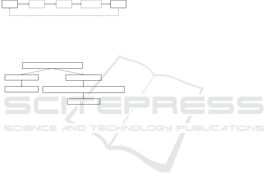
The 5 hand motions are grasp, release, position, apply pressure and disengage. These motions were
observed to commonly occur in the order illustrated in Figure 2.13.
Grasp Disengage
Position
Apply pressure
Release
Move
Reach
Figure 2.13: Hand motions cycle in MTM-1. The dashed motions are optional in a cycle.
The grasp and release motions are always present in a cycle. Their code and differentiation options are
displayed in Tables 2.1 and 2.2. The motions disengage, position and apply pressure are optional in a
cycle and are performed while holding an object, so between grasping and releasing. After pressure is
applied, the object is commonly released. While it is plausible to have multiple positioning or disengag-
ing motions in a cycle, it is not common for most tasks. The algorithm in this state is not able to detect
multiple disengage or position motions in one cycle. It is however able to detect the standard interaction
with an object that involves both of the motions in one cycle. That would be grasping it, disengaging it
from somewhere, position it somewhere else and then release it again.
25
Figure 2: Hand motions cycle in MTM-1. The dashed mo-
tions are optional in a cycle.
Fig. 3 represents the general idea of our decision
tree approach. We first check if either grasping the
object or releasing it was performed.
Decision trees Roman’s work
gorobets
June 2024
Hand motion type (grasp or release)
Grasp transcription
Reach transcription
Release transcription
Crank/position/disengage transcription (optional)
Move transcription
1
Figure 3: Interconnection between different motions.
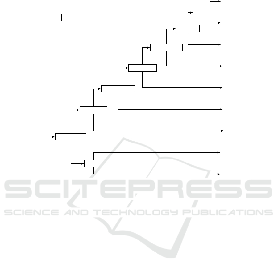
3.3.1 Hand Motion Decision Tree
The hand decision tree (Fig. 4) is triggered when the
beginning or the end of touching a VO occurs. First,
we check whether we detected the beginning or end
of the virtual hand collision with the VO. If we detect
the end, we transcribe the release motion; otherwise -
a grasp motion. To distinguish between two different
types of release, the previous grasp is considered. If
it was G5, then RL2 is transcribed, otherwise RL1.
Distinguishing between different grasping types
requires additional knowledge about the grasped ob-
ject. In VR, it is possible to get information about
VO’s features. In our approach, we manually labeled
each VO if it was small, cylindrical, or in a group of
similar objects. It is easy to do as we are manually
setting the VE and all VOs in it. Once a grasping ac-
tion is detected, we check whether a regrasp of the
same object with the same hand was performed. For
this, we introduce a time limit of 1 second between the
time when an object was placed and grasped again. If
it is less than 1 second, we transcribe regrasp. Oth-
erwise, we check if the object was passed to another
hand without being put back on the surface. In this
case, we transcribe G3. Next, we consider whether a
VO has a label of being in a group (G4) or if it is la-
beled as small (G1B) or cylindrical (G1C). If neither
of those is true, we transcribe it as a normal grasp-
ing (G1A). Additionally, we check whether the hand
is properly closed or not (G5).
Fig. 4 shows all grasping motions (except regrasp-
ing), and triggers the arm decision tree that transcribes
a preceding arm motion with the consideration of the
recently transcribed hand motion. Hand motions po-
sition and apply pressure require knowledge about the
applied force. As this is not applicable in VR, our im-
plementation of apply pressure detection is based on
knowledge about the process. In our user study (Ta-
ble 4), we automatically transcribe AP code when the
screwing task is performed, as we know that this pro-
cess requires the application of the force in reality.
Similarly, our algorithm can not detect different
specifications of the position hand motion. However,
we combined them into one motion without specifica-
tions. We transcribe position when a VO reaches its
predefined location. For example, as soon as the ham-
merhead is properly positioned on the corresponding
red rectangle, we transcribe position. Disengage hand
motions appear when a previously inserted nail is ex-
tracted from a hole. We track two engaged VOs: if
they were engaged during the preceding grasping and
no longer touch each other after the release motion is
detected, we transcribe it as disengage.
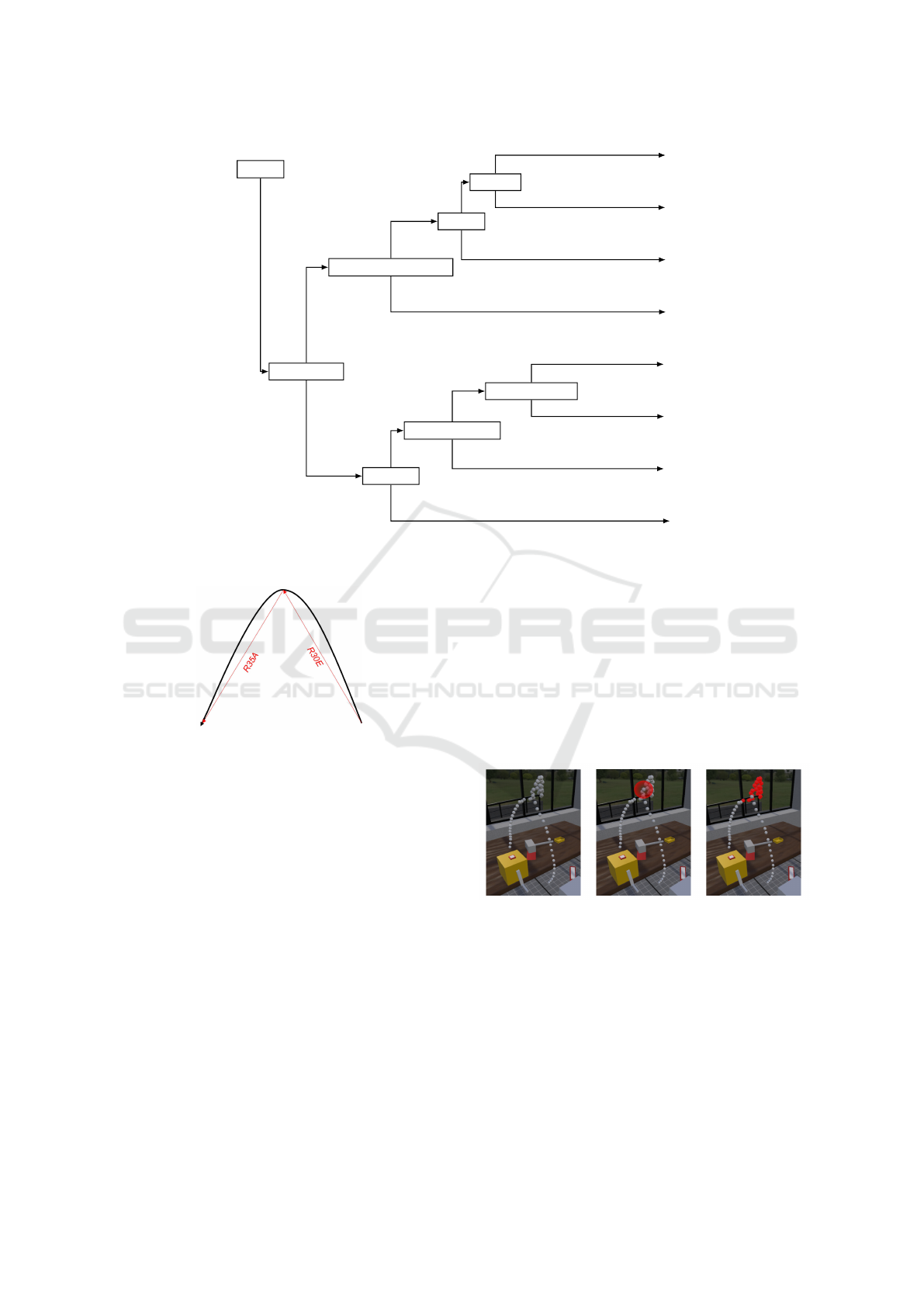
3.3.2 Arm Motion Decision Tree
The arm decision tree (Fig. 5) is triggered by the out-
put of the hand decision tree. Once the MTM-1 code
for the hand motion is derived, we can also confirm
that the corresponding arm motion was performed.
It is important to note that the turn motion does
not intuitively fit into the arm motions category. Its
definition is the turning of the wrist during a reach or
move motion. Thus, it is always accompanied by arm
motions and is best suited to this category. In a man-
ual transcription, an expert would determine which
motion requires more TMUs and only transcribe the
higher one. So either the turn or the reach/move mo-
tion. However, since this algorithm focuses on mo-
tion detection, it transcribes the turn motion along-
side with reach/move motion. This decision tree is
triggered once the corresponding MTM-1 code for
the hand action is received. Based on this output we
check if it was a release motion or not. If the VO
was released, that means that it was either moved to a
new location or a cranking action was performed. If
not, that means that the object was grasped, and the
preceding corresponding arm motion was reach.
To distinguish between cranking and moving, we
check the label of the VO. If the released VO has the
Automatic Transcription and Detection of the MTM-1 Hand Motions Performed in Virtual Reality
599
2 Methodology
T rigger
h
1
: is release
h
2
: !G5
RL1
∗∗
RL2
∗∗
h
3
: regrasp
G2
h
4
: other hand
G3
∗
h
5
: grouped
G4
∗
h
6
: open hand
G5
∗
h
7
: small
G1B
∗
h
8
: cylindrical
G1C
∗
G1A
∗
T
T
F
F
T
F
T
F
T
F
T
F
T
F
T
F
Figure 2.14: Decision tree for the hand motions. When the decision tree gets triggered, the algorithm starts with
the statement h
1
and follows the branches until it reaches a leaf, deciding on what motion was per-
formed. T stands for T rue and F for F alse.
*: These leafs automatically trigger the arm motions decision tree.
**: These leafs additionally check for other hand motions.
If the motion is a release (RL1, RL2), the algorithm examines if any position or dissengage motions
occurred during the hand motion cycle. The object’s interaction values provide information on whether
it was disengaged or positioned during the interaction. The motion notations can be seen in Tables 2.3
and 2.4.
28
Figure 4: Decision tree for hand motions. When the decision tree is triggered, the algorithm starts with the statement h1 and
follows the branches until it reaches a leaf, deciding on what motion was performed. T stands for True and F for False.
*: These leaves automatically trigger the arm motions decision tree.
**: These leaves additionally check for other hand motions.
label “crank”, we transcribe a cranking motion. Oth-
erwise, we transcribe one of the move arm motions.
For further transcription of the move basic actions, we
first check whether a VO requires precise positioning.
We define a boolean variable for every VO that needs
to be positioned at a particular location. This variable
is true when the VO’s position matches the target po-
sition. When this variable is true, we transcribe MC
basic action. If not, we are checking whether or not
it was passed to another hand. This event is detected
when the VO gets attached to another virtual hand.
Therefore, if the VO was passed to another hand, we
transcribe MA MTM-1 code; otherwise MB.
To distinguish different types of reach motions,
we first check if the reach motion can be performed
without looking at the object. This is true if the ob-
ject is either passed from one hand to another (G3) or
is at a fixed location. Such a reach motion requires
fewer TMUs than others and is transcribed as RA.
Otherwise, we check if the corresponding grasping
hand motion involved choosing the VO (G4). Then
the reach motion requires more precision and is tran-
scribed as RC. Lastly, we check whether the corre-
sponding grasping was performed on a small object
(G1B). If so, we transcribe RD, which corresponds to
reaching a small object. Otherwise, we transcribe RB.
3.3.3 Motions that Do not Involve VOs
The hand- and arm decision trees were based on the
principle of interaction with a VO. They cover all ba-
sic hand and arm MTM-1 motions (Table 2 and 3),
except for RE and MD, which are reaching or moving
to an undefined location. An example for an RE is a
waving motion, and MD would be swinging a ham-
mer. The difference is that the move motion carries an
object. Figure 6 shows an example of a hand reach-
ing up to signal a colleague and then down to press
a button. In MTM-1, these motions would be tran-
scribed as an RE motion followed by an RA to press
the button (as indicated by the red arrows).
Transitional motions are detected using the DB-
SCAN (Density-Based Spatial Clustering of Applica-
tions with Noise) algorithm. DBSCAN is a clustering
algorithm that is commonly used in machine learning
and data mining (Schubert et al., 2017). It is a density-
based algorithm that groups data points that are close
to each other, forming clusters, while also identifying
points that are outliers or noise. The DBSCAN fol-
HUCAPP 2025 - 9th International Conference on Human Computer Interaction Theory and Applications
600
2.6 Transcription algorithm
a
6
: Grasp was G4
Explanation: If the grasp involved choosing and is transcribed as G4, the reach motion
requires more precision and is transcribed as RC.
Possible codes if T rue: {RC}
Possible codes if F alse: {RB, RD}
a
7
: Grasp was G1B
Explanation: If the grasped object was very small, indicated by a transcribed G1B
motion, the reach motion has to be very precise and is transcribed as RD.
Possible codes if T rue: {RD}
Possible codes if F alse: {RB}
T rigger
a
1
: is release
a
2
: crank
C
a
3
: got positioned
MC
a
4
: to other hand
MA
MB
a
5
: G3 ∧ fixed location
RA
a
6
: G4
RC
a
7
: G1B
RD
RB
T
T
F
T
F
T
F
F
T
F
T
F
T
F
Figure 2.15: Decision tree for the arm motions. When the decision tree gets triggered by the hand motions, the
algorithm starts with the statement a
1
and follows the branches until it reaches a leaf, deciding on
what motion was performed. T stands for T rue and F for F alse.
33
Figure 5: Decision tree for arm motions. When the decision tree gets triggered by the hand motions, it starts with the statement
a1 and follows the branches until it reaches a leaf, deciding on the performed motion. T stands for True and F for False.
Figure 6: Transitional motion example: The black curve
represents the path of a hand that reaches up to signal a
colleague and then reaches down to touch a button. Corre-
sponding MTM-1 motions are shown in red.
lows the human intuitive way of grouping data points
(Yu et al., 2019).
DBSCAN takes two parameters: ε and minPts.
ε is a radius around each point within which other
points are considered to be in the same neighborhood.
minPts is the minimum number of points required in a
neighborhood, to form a dense region or cluster. Fig-
ure 7 displays the trajectory data of a hand perform-
ing the motion sequence introduced in Figure 6. The
parameters ε = 0.02 m and minPts = 10 were cho-
sen empirically by performing a pilot test run. The
DBSCAN algorithm is applied every time a reach or
move motion is transcribed by the arm motion deci-
sion tree. Otherwise, for RE or MD motions that
don’t require any grasping or releasing of a VO will be
missing and considered as a part of the reach or move
motion transcribed by the arm motion decision tree.
The input data for DBSCAN is the stored trajectory
of the hand performing the motion. For a reach mo-
tion, the trajectory between the corresponding release
and grasp hand motion will be considered. Likewise,
for a move motion the trajectory between the corre-
sponding grasp and release motions will be used. For
every cluster from the DBSCAN algorithm, an addi-
tional transitional motion (RE or MD) is transcribed
alongside the original reach or move motion that is
transcribed by the arm motion decision tree.
Figure 7: DBSCAN: Left: A set of spatial data points from
a hand performing a signaling motion and then pressing a
button. DBSCAN selects a data point and creates a sphere
of spatial proximity around it (middle). If the number of
neighboring data points exceeds the minPts threshold, they
are clustered (right). This process repeats until all the data
points are either clustered or labeled as outliers.
4 RESULTS AND DISCUSSION
This section presents the results of our automatic tran-
scription. We conducted a user study with 33 partici-
Automatic Transcription and Detection of the MTM-1 Hand Motions Performed in Virtual Reality
601

pants. To verify the results, the MTM-1 codes that are
automatically obtained by the algorithm are compared
to the ones obtained manually. We labeled all auto-
matically delivered MTM-1 codes as one of the three:
True Positive (TP), False Positive (FP), or False Neg-
ative (FN). When our algorithm correctly transcribes
a motion that was performed by the participant, we
label it as TP. When it transcribes a motion that is not
performed by the participant, it is FP. When it does
not transcribe a motion even though the participant
performed one, it is FN. Based on TPs, FPs, and FNs,
we also measure Precision and Recall (see Eq. (1)).
Precision =
∑
TP
∑
TP +
∑
FP
, Recall =
∑
TP
∑
TP +
∑
FN
(1)
Precision is the ratio of true positive results to the
total number of positive results. It measures the accu-
racy in identifying true positives. Recall is the ratio
of true positive results to the total number of relevant
results. It measures the completeness of the model in
identifying all relevant results.
4.1 Hand Motion Results
The summary of the results for the hand motions tran-
scription can be seen on Table 5. The recall values
for the basic hand motions are above 90%, indicating
that the algorithm generally does not miss the hand
motions performed by users. Notably, the majority of
the precision values also achieve this threshold, indi-
cating a balanced sensitivity of the motion detection.
However, the regrasp motion G2 and grip release mo-
tion RL1 have a large number of FP values. These
motions are not independent since a regrasp motion
will almost certainly lead to a move and release mo-
tion. These false regrasp motions are mostly caused
by two main reasons. One is the gloves’ tracking is-
sues. And the second one is the lack of hand position
fixation during the screwing task.
When the tracking of the gloves is disturbed, it
causes a false transcription of a release and regrasp
action to appear. Various technical reasons can cause
this disturbance, such as rapid changes in the mag-
netic field or visually obscuring the tracking device.
This causes a false transcription of the RL1 and G2
motions. To avoid such FP results, a threshold could
be implemented that suppresses the transcription in
such cases.
The screwing task caused 11 of the G2 and RL1
motions FPs, since we didn’t restrict the virtual hand
moving through the VO. Therefore, each time an ad-
ditional motion was transcribed. A potential solution
is to snap the virtual hand to the handle of a VO that
needs to be screwed in.
4.2 Arm Motion Results
The results for the arm motion transcription are shown
in Table 6. The algorithm showed good performance
with the precision and recall values above 90%. How-
ever, despite a high recall rate of 100% for the crank
motion detection, the precision of it is slightly below
90% because of the FPs. Those FPs appear along-
side with the transcribed FPs of G2 and RL1 motions.
When a virtual hand goes through the handle of the
virtual crank, it causes a false transcription of the G2
and RL1 hand motions and a wrong transcription of
the C motion.
Additionally, our algorithm has low precision and
recall for the RE and MD motions that do not involve
VOs and are based on the DBSCAN algorithm. As we
manually defined the DBSCAN parameters based on
the pilot run, they were fine-tuned for one particular
user. During the user study, we observed a noticeable
difference in performance those actions between dif-
ferent users. This can be addressed by introducing a
calibration phase performed for each user for a fine-
tuning of the parameters of the DBSCAN algorithm.
5 CONCLUSION
We presented a decision tree-based approach to au-
tomatically detect hand and arm MTM-1 motions in
VR using a hand-tracking VRfree data glove. Our al-
gorithm uses a decision-tree approach for the motions
that include interactions with the VOs. Our approach
is based on the assumption that every hand motion is
preceded by an arm motion, so once a hand motion
is transcribed, our algorithm also transcribes a corre-
sponding arm motion. Additionally, we discussed the
use of the DBSCAN algorithm for the hand and arm
motions transcription, which do not require any VOs.
We counted all TPs, FPs, and FNs based on the au-
tomatic transcription of our algorithm in comparison
to the manually obtained ground truth. Additionally,
we calculated precision and recall of our algorithm
(see Tables 5 and 6). We discussed what caused some
of the FPs and FNs and gave recommendations for the
improvement of the algorithm.
ACKNOWLEDGEMENTS
We want to thank Sensoryx AG for their help with
the gloves maintenance and support, as well as for
providing the tracking environment for the user study.
HUCAPP 2025 - 9th International Conference on Human Computer Interaction Theory and Applications
602
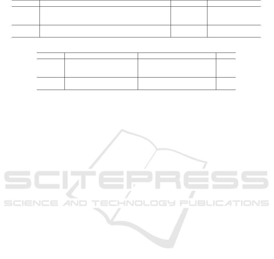
Table 5: Results of the automatic MTM-1 basic hand motion detection.
G1A G1B G1C G2 G3 G4 G5 RL1 RL2 P AP D
TP 94 30 60 70 31 29 64 311 65 60 31 29
FP 0 0 0 21 0 0 4 37 2 0 0 0
FN 2 1 3 0 0 1 2 7 2 2 0 2
Precision 1 1 1 0.769 1 1 0.941 0.894 0.97 1 1 1
Recall 0.979 0.968 0.952 1 1 0.967 0.97 0.978 0.97 0.968 1 0.935
Table 6: Results of the automatic MTM-1 basic arm motion detection.
RA RB RC RE MA MB MC MD C
TP 95 190 29 58 31 251 60 119 34
FP 0 1 0 17 1 25 0 67 4
FN 0 2 1 8 0 2 2 16 0
Precision 1 0.995 1 0.773 0.969 0.909 1 0.64 0.895
Recall 1 0.99 0.967 0.879 1 0.992 0.968 0.881 1
REFERENCES
Andreopoulos, E., Gorobets, V., and Kunz, A. (2024). Au-
tomated transcription of mtm motions in a virtual en-
vironment. In 9th International Congress on Infor-
mation and Communication Technology, pages 1–16,
Cham, Switzerland. Springer.
Bellarbi, A., Jessel, J.-P., and Da Dalto, L. (2019). Towards
method time measurement identification using virtual
reality and gesture recognition. In 2019 IEEE Inter-
national Conference on Artificial Intelligence and Vir-
tual Reality (AIVR), pages 191–1913, New York, NY,
USA. IEEE.
Fantoni, G., Al-Zubaidi, S. Q., Coli, E., and Mazzei, D.
(2020). Automating the process of method-time-
measurement. International Journal of Productivity
and Performance Management, 70(4):958–982.
Gorobets, V., Billeter, R., Adelsberger, R., and Kunz, A.
(2024). Automatic transcription of the methods-time
measurement mtm-1 motions in vr. In AHFE Inter-
national, IHIET-AI, pages 250–259, New York, NY,
USA. AHFE International.
Gorobets, V., Holzwarth, V., Hirt, C., Jufer, N., and Kunz,
A. (2021). A vr-based approach in conducting mtm for
manual workplaces. The International Journal of Ad-
vanced Manufacturing Technology, 117(7–8):2501–
2510.
Maynard, H. B., Stegemerten, G. J., and Schwab, J. L.
(1948). Methods-time Measurement. McGraw-Hill
Book Company, New York, NY, USA.
Schubert, E., Sander, J., Ester, M., Kriegel, H. P., and Xu,
X. (2017). Dbscan revisited, revisited: why and how
you should (still) use dbscan. ACM Transactions on
Database Systems (TODS), 42(3):1–21.
Yu, H., Chen, L., Yao, J., and Wang, X. (2019). A three-
way clustering method based on an improved dbscan
algorithm. Physica A: Statistical Mechanics and its
Applications, 535:122289.
Automatic Transcription and Detection of the MTM-1 Hand Motions Performed in Virtual Reality
603
