
Enabling Incremental SysML Model Verification: Managing Variability
and Complexity Through Tagging and Model Reduction
Bastien Sultan
1 a
, Ludovic Apvrille
1 b
, Oana Hotescu
2 c
and Pierre de Saqui-Sannes
2 d
1
LTCI, T
´
el
´
ecom Paris, Institut Polytechnique de Paris, France
2
F
´
ed
´
eration ENAC ISAE-SUPAERO ONERA, Universit
´
e de Toulouse, France
Keywords:
MBSE, SysML, Model Checking, Model Reduction, Software Product Lines.
Abstract:
Designing complex software systems with model-based approaches encounters the recognized state space ex-
plosion problem. Typically, only a subset of models can be formally verified, forcing reliance on simulation
or testing to verify the entire system. Furthermore, most formal verification tools require a complete reeval-
uation of properties after even minor modifications to a model. Although incremental formal verification,
particularly the incremental model-checking approach of TTool, has been proposed, it still requires modelers
to manually select sub-models not facing state space explosion. Unfortunately, this manual model selection is
susceptible to errors. This paper presents a twofold contribution to SysML models of software product lines.
First, we introduce a SysML model tagging feature that enables designers to explicitly differentiate between
various subsystems, such as core and optional features. Second, we develop and implement a model reduction
algorithm using dependency graphs (DGs). This algorithm automatically deactivate model elements linked
to specific tags, removing both the specified elements and all their logical dependencies provided the DG is
acyclic. These two contributions are evaluated for their effectiveness in generating model variants. Together,
they facilitate the creation of a core model and an associated set of models, each extended by additional model
elements, and make it possible to rely on incremental model-checking. We have implemented the contributions
in TTool and applied it to an integrated modular avionics system. This application enables to compare—both
manual and automated—model reduction strategies and assess their benefits for TTool users.
1 INTRODUCTION
Over the past decade, systems engineering has
switched from a document-based paradigm to a
model-based paradigm. The acronym MBSE (Model-
Based Software and Systems Engineering) was
coined accordingly. The expected benefits of us-
ing MBSE are many (de Saqui-Sannes et al., 2022),
and include early detection of design errors in the
life cycle of systems. This early detection may be
achieved using model-based formal verification tech-
niques (Cederbladh et al., 2024). One of the well-
established formal verification techniques is model-
checking: the model of the system is checked against
a set of properties and a “satisfied/unsatisfied” answer
is returned for each property.
Since SysML (OMG, 2022) is a common mod-
eling language employed in Model-Driven Engineer-
a
https://orcid.org/0000-0002-5031-5794
b
https://orcid.org/0000-0002-1167-4639
c
https://orcid.org/0000-0001-6612-8574
d
https://orcid.org/0000-0002-1404-0148
ing (MDE) and MBSE methodologies, various meth-
ods, algorithms, and tools have been developed to
support formal verification of SysML models (Wang
et al., 2019; Horv
´
ath et al., 2020; de Saqui-Sannes
et al., 2021). Among these, TTool
1
integrates a
model checker that enables for direct verification of
CTL properties on SysML semantics (Calvino and
Apvrille, 2021), unlike SysML tools that rely on ex-
ternal verification tools (Cederbladh et al., 2024).
Model checking is however hindered by combinato-
rial explosion issues, due to the complexity of the
models being verified. Verifying relevant sub-models
(or sub-systems) is one way to circumvent combi-
natorial explosion. Incremental verification, as the
one introduced in (Coudert et al., 2024), also made
a step towards addressing this challenge. SysML
model design can be seen as an incremental process
and incremental model-checking proposes solutions
to not entirely verify the complete set of model prop-
erties when an additive increment partly modifies the
SysML model under design. Building on that work,
1
https://ttool.telecom-paris.fr
224
Sultan, B., Apvrille, L., Hotescu, O. and de Saqui-Sannes, P.
Enabling Incremental SysML Model Verification: Managing Variability and Complexity Through Tagging and Model Reduction.
DOI: 10.5220/0013182300003896
Paper published under CC license (CC BY-NC-ND 4.0)
In Proceedings of the 13th International Conference on Model-Based Software and Systems Engineering (MODELSWARD 2025), pages 224-233
ISBN: 978-989-758-729-0; ISSN: 2184-4348
Proceedings Copyright © 2025 by SCITEPRESS – Science and Technology Publications, Lda.

the current paper presents a complementary solution
to further address these issues. It considers systems
designed with a core set of functions that can be aug-
mented with optional features, a common practice in
e.g., automotive systems (Hohl et al., 2018), and more
broadly within software product lines. In this context,
these different system versions are typically referred
to as variants (Garmendia et al., 2024). Verifying
models of such systems can be approached incremen-
tally: first, by verifying the model’s subpart that rep-
resent the core functions, and subsequently, by adding
and verifying the optional functions one at a time (or
several among all), and verifying if the properties of
the core model are still satisfied by utilizing incre-
mental model checking approaches that reuse the pre-
vious proof results (Cordy et al., 2012; Coudert et al.,
2024). The paper introduces two contributions to sup-
port this incremental verification process:
1. A tagging feature for SysML models that enables
model designers to easily classify the different
model elements for various purpose: history, fea-
ture characteristics, core features vs. optional fea-
tures, abstraction level—enabling the generation
of multiple model variants with different degrees
of abstraction from a single model, etc. In this pa-
per, we demonstrate the interest of this tagging ap-
proach for differentiating core functions from op-
tional features, facilitating the distinction between
different system variants.
2. A model reduction algorithm based on depen-
dency graphs (DG)—graphs we assume to be
equivalent to SysML models as defined in the
paper—that enables the deactivation of elements
associated with specified input tags, including
their logical dependencies in the model
2
. In
complex models, performing this model reduc-
tion manually can be both tedious and error-prone.
Indeed, some logical dependencies of a tagged
element may span across multiple diagrams—
typically, removing a tagged send signal opera-
tor in a state-machine diagram involves removing
the related receive signal operators from any other
state-machine diagrams where they are present.
These contributions have been integrated into the
SysML modeling and verification toolkit TTool.
This paper is organized as follows. Section 2 de-
fines the SysML diagrams used throughout the cur-
rent paper. Section 3 presents the contributions of the
current paper, namely SysML models tagging and the
reduction algorithm. Section 4 evaluates our contribu-
2
The algorithm ensures the deletion of all the logical
dependencies if the DG is acyclic, and of all the path de-
pendencies, as defined below, if the graph contains cycles.
tions on a case study: an avionics system. Section 5
surveys related work, and Section 6 concludes the pa-
per.
2 SysML BACKGROUND
This section introduces key definitions for a subset of
SysML, borrowed from (Apvrille et al., 2021; Coud-
ert et al., 2024), for the sake of self-containment.
Definition 1 (Block instance).
A block instance is a 7-tuple B =
⟨A,M, P,S
i
,S
o
,smd,B
p
⟩ where A is a set of inte-
ger or boolean attributes, M is a set of methods, P is
a set of ports, S
i
and S
o
are sets of input and output
signals, smd is a state machine diagram, and B
p
represents the parent block B belongs to.
Each block instance contains one finite state ma-
chine.
Definition 2 (State machine).
A finite state machine is a directed graph ⟨s
0
,S, T ⟩
where:
• S is a set of states (s
0
∈ S is the initial state).
• T is a set of transitions
⟨s
start
,a f ter, condition,Actions,s
end
⟩ where:
– s
start
is the initial state of the transition.
– a f ter(t
min
,t
max
) specifies that the transition is
enabled only after a duration between t
min
and
t
max
has elapsed.
– condition is a Boolean expression that con-
ditions the execution of the transition. This
Boolean expression can use block attributes.
– action ∈ {variable affectation, send signal, re-
ceive signal} represents the action attached to
the transition. The action can be executed only
once the transition has been enabled, i.e., when
the a f ter clause has elapsed and the condition
equals true.
– s
end
is the final state of the transition.
Definition 3 (Block instance diagram).
A block instance diagram (or SysML model) is a
3-tuple ⟨B,connect,assoc⟩ where:
• B is a set of block instances. We denote with
P =
S
B∈B
P
B
the set of all ports of B and with
S
o
=
S
B∈B
S
oB
(resp. S
i
=
S
B∈B
S
iB
) the set of all out-
put (resp. input) signals of B.
• connect is a function P × P →
{No,synchronous,asynchronous} that returns
the communication semantics between two ports.
Enabling Incremental SysML Model Verification: Managing Variability and Complexity Through Tagging and Model Reduction
225

• assoc is a function P × S
o
× P × S
i
→ Bool that
returns true if an output signal s
o
of block B
1
is
associated to an input signal s
i
of block B
2
via
2 ports p
1
, p
2
of respectively of B
1
and B
2
, and
if these two ports are connected. In addition, a
signal cannot be associated with more that one
port and one signal.
3 TAGGING AND REDUCING
SysML MODELS
The current paper primarily introduces two new fea-
tures into TTool: (1) the ability to manually assign
tags to elements of a SysML model and (2) a one-click
model reduction feature. The model reduction fea-
ture, given a set of input tags and a model, generates a
new model that excludes elements associated with the
specified tags and (at least part of) their logical de-
pendencies. This reduction process relies on model-
to-DG and graph-to-model generation algorithms al-
ready implemented in TTool (Apvrille et al., 2021),
as well as a new graph reduction algorithm proposed
in the paper.
3.1 Background on Dependency Graphs
The main contributions of the current paper are based
on DGs (Apvrille et al., 2021). A DG is a directed
graph (V
DG
,E
DG
) constructed from a SysML model
as defined in Definition 3. In this graph, the vertices
V
DG
represent the behavioral elements of the SysML
model (i.e., states and transitions), while the edges
E
DG
⊆ V
2
DG
represent the sequential dependencies be-
tween these elements (e.g., which state is connected
to which transition) and the communication seman-
tics between blocks. Some of the vertices have no
incoming edges: they represent the initial states of
the SysML model’s state machine diagrams, and all
the other vertices are reachable from at least one path
originating from one of these source vertices. The
vertices are labeled with information that enables re-
constructing the SysML model from the graph: e.g.,
the block to which the state/transition represented by
the vertex belongs, or the type of element the vertex
represents. For the needs of the following definitions,
we introduce a function isCommVertex : V
DG
→ Bool
which indicates whether a vertex represents a transi-
tion containing a send/receive signal within its action
set. Last, we assume that this graph is semantically
equivalent to the SysML model: for a given SysML
model M, graphToModel(modelToGraph(M)) ≡ M.
Several reduction algorithms for these DGs were pre-
viously proposed (Apvrille et al., 2021; Apvrille et al.,
2023) in the context of model checking. They are
used to reduce a DG with respect to a given prop-
erty, enabling model-checking algorithms to work on
smaller models. The algorithm introduced in this sec-
tion operates differently, reducing the DG based on a
set of input tags, in a manner that is entirely agnostic
to the properties to be verified.
3.2 Tagging
We define below the tagging operation. Tags can
be assigned to the following elements of a SysML
model: blocks, associations between blocks (i.e., con-
sidering a SysML model such as defined in Defini-
tion 3, elements of {(p
1
, p
2
) ∈ P
2
|connect(p
1
, p
2
) ̸=
No}), states, and state-machine transitions.
Definition 4 (Tagging).
Let A∗ = {a,A, .. ., z,Z}∗ be the set of finite words
and M = ⟨B,connect,assoc⟩ be a SysML model. For
each B ∈ B, we denote its state-machine diagram with
⟨s
0B
,S
B
,T
B
⟩. Let T =
S
B∈B
T
B
and S =
S
B∈B
S
B
.
A tagging is a total function tag : B ⊔ P
2
⊔ S ⊔
T →℘(A∗)
3
that associates a set of tags with blocks,
port associations, states and transitions of M.
Since DGs shall be semantically equivalent to
SysML models, we have also introduced the ability
to tag vertices.
Definition 5 (Graph tagging).
Let A∗ = {a,A, .. ., z,Z}∗ be the set of finite words
and (V, E) be a graph.
A graph tagging is a total function tag
G
: V →
℘(A∗).
The tags are preserved when a model is converted
to a DG. Given a SysML model M and its correspond-
ing graph (V,E) = modelToGraph(M), for every ver-
tex v ∈ V , if e denotes the block, state, or transition
represented by v, then tag
G
(v) = tag(e).
These definitions form the basis for the graph re-
duction algorithm.
3.3 Tag-Driven Reduction
3.3.1 Preliminary Definitions
The reduction algorithm introduced in the current pa-
per relies on the concept of logical dependency in
DGs. The logical dependencies of a given vertex
are defined as the union of its path dependencies and
communication dependencies, as described below. In
3
℘(A∗) is the powerset of A∗ and A ⊔ B denotes the
disjoint union of A and B (A ∪ B with A ∩ B =
/
0).
MODELSWARD 2025 - 13th International Conference on Model-Based Software and Systems Engineering
226
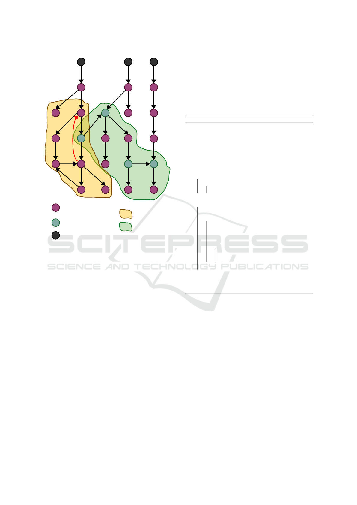
u
Vertex v where
¬isCommVertex(v)
Vertex v where
isCommVertex(v)
Source vertex
D
π
(u)
D
γ
(u)
Figure 1: Example DG for illustrating Definitions 6 to 8.
those three definitions, (V, E) is a (finite) directed
graph.
Definition 6 (Path dependency).
Let V
s
= {v ∈ V | ∀u ∈ V,(u,v) /∈ E}.
A vertex t is a path dependency of a vertex u
if ∀s ∈ V
s
,∀{(s,v
1
),(v
1
,v
2
). ..,(v
n
,t)} ⊆ E,(s = u ∨
∃i ∈ J1, nK s.t. v
i
= u).
The function D
π
: V →℘(V ) associates each ver-
tex with the set of its path dependencies.
Definition 7 (Communication dependency).
We define the function γ : V × N → ℘(V ) by the
following recurrence relation:
• γ(u,0) = {v ∈ V | isCommVertex(v) ∧ ∃w ∈ {u} ∪
D
π
(u),(w,v) ∈ E}.
• γ(u,n + 1) = γ(u,n)∪{v ∈ V | isCommVertex(v)∧
∃w ∈ γ(u, n),(w,v) ∈ E} ∪
S
v∈γ(u,n)
D
π
(v).
The set of communication dependencies of a ver-
tex u ∈ V is then defined as γ(u,i) where i is such that
γ(u,i +1) = γ(u, i).
The function D
γ
: V → ℘(V) associates each ver-
tex with the set of its communication dependencies.
Definition 8 (Logical dependency).
The set of logical dependencies of a vertex u ∈ V
is defined as D
π
(u) ∪ D
γ
(u). For the rest of the paper,
we define the total function
logdep : V
2
→ Bool
(t, u) 7→
(
⊤ if t ∈ D
π
(u) ∪ D
γ
(u)
⊥ otherwise.
3.3.2 Tag-Driven Reduction Algorithm
Algorithm 1: Tag-driven graph reduction.
Data: Dependency graph DG
I
= (V
I
,E
I
),
T ∈ ℘(A∗), graph tagging function
tag
G
: V
I
→℘(A∗)
Result: Reduced graph G
R
= (V
R
,E
R
)
1 (V
R
,E
R
) ← (
/
0,
/
0)
2 V
rem
←
/
0
3 Boolean continue ← ⊤
4 foreach v ∈ V
I
do
5 if T ∩ tag
G
(v) ̸=
/
0 then
6 V
rem
← V
rem
∪ {v}
7 end
8 while continue do
9 continue ← ⊥
10 foreach v ∈ V
I
do
11 if v /∈ V
rem
∧ (E
I
∩V
I
× {v} ⊆
V
rem
× {v}) ∨ (isCommVertex(v) ∧
(E
I
∩V
I
× {v}) ∩V
rem
× {v} ̸=
/
0)
then
12 V
rem
← V
rem
∪ {v}
13 continue ← ⊤
14 end
15 end
16 V
R
← V
I
\V
rem
17 E
R
← E
I
∩V
2
R
Algorithm 1 generates a graph by removing a set of
vertices, V
rem
(line 2), from the input DG (V
I
,E
I
). The
set V
rem
is initially populated with vertices from V
I
that are associated with at least one tag from the in-
put tag set T (lines 4-7). Subsequently (lines 8-14),
the algorithm adds to V
rem
any vertex from V
I
whose
incoming edges all originate from vertices in V
rem
.
This enrichment of V
rem
is performed recursively un-
til no additional vertex in V
I
\V
rem
has all its incom-
ing edges originating from vertices in V
rem
. Finally, a
new graph (V
R
,E
R
) is constructed by subtracting V
rem
from V
I
and by deleting from E
I
every edge involving
a vertex in V
rem
(lines 16-17). Afterwards, a graph-to-
model reconstruction algorithm already implemented
in TTool builds a model based on the reduced graph.
Overall, our two contributions interrelate as fol-
lows. The process begins with the user providing a
SysML model (i.e., a block diagram and a set of state-
machine diagrams). Using the tagging feature in the
Enabling Incremental SysML Model Verification: Managing Variability and Complexity Through Tagging and Model Reduction
227

TTool’s graphical user interface or command-line in-
terface, the user assigns tags to elements of the model.
When necessary (e.g., when only the core model, or
a variant including a subset of optional features, is
needed), the user then specifies a list of tags refer-
ring to the elements to deactivate in the model. Based
on this input, TTool computes the DG, applies Algo-
rithm 1 to derive a new graph, and outputs the re-
duced SysML model built from this graph thanks to
the pre-existing graph-to-model reconstruction algo-
rithm. Currently, this reduction process guarantees
the removal of all logical dependencies only for cer-
tain classes of SysML models, as discussed below.
Proposition 1. In the absence of additional assump-
tions about the input DG, Algorithm 1 guarantees the
deletion of all the logical dependencies of a vertex
tagged with an input tag iff the input DG is acyclic.
Proof. Let (E
I
,V
I
), T ∈ ℘(A∗) and tag
G
: V
I
→
℘(A∗) be the input DG, set of tags and graph tagging
function. Assume that ∃v ∈ V
I
s.t. ∃v
t
∈ {v ∈ V
I
|T ∩
tag
G
(v) ̸=
/
0},logdep(v,v
t
) ∧ v /∈ V
rem
. Therefore
¬((E
I
∩V
I
×{v} ⊆ V
rem
×{v})∨(isCommVertex(v)∧
(E
I
∩V
I
× {v}) ∩ V
rem
× {v} ̸=
/
0)) (lines 8-14 of Al-
gorithm 1). Equivalently, this can be expressed as:
¬isCommVertex(v)∧ ∃(v
′
,v) ∈ E
I
,v
′
/∈ V
rem
∨∀(v
′
,v) ∈ E
I
,v
′
/∈ V
rem
(1)
We first prove the following lemma:
Lemma 1. In an acyclic DG, Algorithm 1 removes
every path dependency of a vertex tagged with an in-
put tag.
We start by noting that (1) =⇒ ∃(v
′
,v) ∈ E
I
,v
′
/∈
V
rem
and will prove that a contradiction arises from
this weaker condition. At this point, we have two pos-
sible cases:
1. tag
G
(v
′
) ∈ T : in that case, v
′
∈ V
rem
(lines 5-6 of
Algorithm 1) and we have a contradiction.
2. tag
G
(v
′
) /∈ T . Since v
′
/∈ V
rem
, we can apply the
same reasoning and deduce that ∃(v
′′
,v
′
) ∈ E
I
s.t.
v
′′
/∈ V
rem
. By induction, since (V
I
,E
I
) is a di-
rected acyclic graph we can continue this process
to build a path leading to v and originating from
a vertex with no incoming edges, where no vertex
on this path is associated with any tag from T . We
can here invoke Definition 6 to note a contradic-
tion and conclude that ∄v ∈ V
I
s.t. ∃v
t
∈ V
T
,v ∈
D
π
(v
t
) ∧ v /∈ V
rem
, which proves Lemma 1.
From the above, we now infer that the vertex v satis-
fying (1) is necessarily a communication dependency
of v
t
. Using an inductive argument analogous to the
one used in the proof of Lemma 1, it follows from
(1) that no edge (u,w) where isCommVertex(w) and
u ∈ V
rem
⊇ {v
t
} ∪ D
π
(v
t
)
4
, can exist on any path from
a source vertex to v, which contradicts Definition 7.
Finally, recalling Definition 8 ends the proof of the
sufficient condition.
Now, if the input graph is not acyclic, a logical
dependency v may have an incoming edge originating
from a cycle, where all vertices on the cycle are path
dependencies of v. Such a vertex invalidates the
condition E
I
∩ V
I
× {v} ⊆ V
rem
× {v} (Algorithm 1,
line 11) since the vertices of the cycle, only reachable
thanks to paths originating from v, do not belong to
V
rem
. If ¬isCommVertex(v), v will not be added to
V
rem
by the algorithm, which proves the necessary
condition. □
However, even if Algorithm 1 overlooks any log-
ical dependencies of a vertex v
t
associated with an
input tag, lines 4–6 ensure that v
t
is removed from
the graph. Therefore, since by Definition 6, any path
originating from a vertex representing the initial states
of a state machine diagram and leading to a path de-
pendency of v
t
must pass through v
t
, no path remains
in the reduced graph that leads to one of these over-
looked dependencies from a source vertex. TTool’s
reconstruction algorithms will ignore these vertices
during the model reconstruction phase, producing a
model from the partially reduced graph that is free
from all elements corresponding to the path depen-
dencies associated with the input tags. From the per-
spective of model reduction, Algorithm 1 thus ad-
dresses a broader range of cases than models asso-
ciated with an acyclic DG. However, some communi-
cation dependencies remain in the output graph, and
their corresponding elements in the reduced model, if
the input model is such that its DG contains a cycle
of logical dependencies of a tagged vertex, involving
a vertex associated with a communication label (e.g.,
the cycle closed by the red arrow in Figure 1).
3.4 Methodological Insight
The tag-based variability management approach pre-
sented in the current paper is designed to integrate
into a broader model-driven engineering framework.
The anticipated benefits, given below, vary depend-
ing on whether the model captures high-level system
aspects or low-level algorithmic details.
Formal Verification (for Both Systems and Low-
Level Algorithmic Models): by generating portions
of the model that can be independently verified, the
complexity of the proof can be reduced. Addition-
ally, in a software product line engineering context,
the tagging and reduction approach enables for the
4
{v
t
} ∪ D
π
(v
t
) ⊆ V
rem
is guaranteed by Lemma 1.
MODELSWARD 2025 - 13th International Conference on Model-Based Software and Systems Engineering
228

generation of a family of models from a complete
model. Each model element corresponding to a fea-
ture is first tagged (one tag per feature). The reduction
is then performed by excluding all tags (to generate a
core model), followed by excluding specific tags se-
lected by the user, depending on the feature content
of each variant. This results in a set of models com-
prising a core model and several variants that extend
the core. It is now possible to rely on TTool’s incre-
mental model-checking algorithm: instead of verify-
ing all properties on the entire model at once, this al-
gorithm reuses previous proof results (e.g., from the
core), checking if the properties still hold, rather than
performing a full exploration of the state space each
time an new optional feature is evaluated on each vari-
ant. With this approach, verifying a model variant
does not require a comprehensive exploration of the
state space, similar to the method proposed by (Cordy
et al., 2012).
Code Generation (for Low-Level Algorithmic
Models): the tagging and reduction approach enables
users to generate multiple applications with just a
few clicks from a same model. Moreover, the code
generated from a reduced model focuses only on the
required functionality, optimizing both the size and
complexity of the software. This is particularly im-
portant in application domains such as embedded sys-
tems.
4 EVALUATION AND
DISCUSSION
An Integrated Modular Architecture, or IMA for
short, serves a case study. An IMA offers comput-
ing, communication, and I/O services for modern em-
bedded systems in domains such as automotive (F
¨
urst
et al., 2009) and avionics (Bieber et al., 2012). IMA
design requires rigorous development processes that
include formal verification techniques. Because of
frequent changes during the development of IMA ar-
chitectures, the approach proposed in the current pa-
per may be applied for it simplifies formal verification
when including new features or existing ones.
4.1 IMA Architecture
Let us consider an IMA architecture model composed
of 4 computing modules (represented by blocks CM1,
CM2, CM3 and CM4, see Figure 2) and a network
(block Network) interconnecting the modules and al-
lowing communication between them via messages. 9
tasks are distributed among the 4 computing modules
contributing to the execution of 4 applications:
• Application 1: Task1 → Task3 → Task6
• Application 2: Task2 → Task7 → Task4 → Task5
• Application 3: Task2 → Task6 → Task8
• Application 4: Task9 → Task5 → Task1
Each task requires for its execution an amount of
computing resources defined as the workload. The
total workload on a module cannot exceed the total
amount of resources available on that module.
4.2 Tagging and Reduction of the IMA
Model
The IMA model may be reduced manually by the
user of TTool or using the tagging and the algorith-
mic reduction approach presented in the current pa-
per. The core features of the system are considered
to be the applications provided by the modules CM1,
CM2, and CM4, with an optional variant of the system
that additionally includes the applications from mod-
ule CM3. The reduction process therefore involves
disabling Application 1 and Application 2, and by
consequence the software tasks task3 and task4 exe-
cuted by the module CM3. We evaluate two reduction
strategies:
(1) Over-Approximation Strategy: this approach re-
moves the entire CM3 block from the model, along
with all transitions in the state-machine diagrams of
other blocks that are synchronized with the transitions
of CM3’s state-machine diagram. This approach re-
quires:
• By Hand: removing the CM3 block, and then re-
moving every transition in the state-machine di-
agrams involving an incoming or outgoing sig-
nal linked to CM3’s signals as well as states only
reachable from these transitions.
• With the Algorithmic Reduction Approach:
tagging CM3 with a tag t, and launching the re-
duction algorithm for the tag t.
(2) Fine Reduction Strategy: in addition to the above
one, this strategy deletes elements in the other state-
machine diagrams that depend to some extent on the
CM3 block, but are not synchronized with transi-
tions in its state-machine diagram (e.g., transitions
with guards involving values that can only be reached
when a signal is received from CM3’s state-machine).
This approach requires:
• By Hand: removing every transition, and subse-
quently removing the states that are only reach-
able via those transitions, where the transitions
depend on values carried by signals from the CM3
block.
Enabling Incremental SysML Model Verification: Managing Variability and Complexity Through Tagging and Model Reduction
229

<<datatype>>
Task
- id : int;
- input : int;
- workload : int;
- period : int;
- computationResult : int;
- previousTask : int;
- nextTask : int;
block
CM3
- availableRessources : int;
- totalWorkload : int;
- task3 : Task;
- task4 : Task;
- message : Message;
~ out toNetwork(Message ...
~ in fromNetwork(Message...
"optionalApp"
block
CM1
- availableRessources : int;
- totalWorkload : int;
- task1 : Task;
- task2 : Task;
- message : Message;
~ out toNetwork(Message ...
~ in fromNetwork(Message...
block
CM4
- availableRessources : int;
- totalWorkload : int;
- task7 : Task;
- task8 : Task;
- task9 : Task;
- message : Message;
~ out toNetwork(Message ...
~ in fromNetwork(Message ...
block
CM2
- availableRessources : int;
- totalWorkload : int;
- task5 : Task;
- task6 : Task;
- message : Message;
~ out toNetwork(Message ...
~ in fromNetwork(Message...
<<datatype>>
Message
- id : int;
- source : int;
- destination : int;
- payload : int;
block
Network
- netDelay : int;
- msg : Message;
~ in fromCM1(Message ...
~ out toCM1(Message ...
~ in fromCM2(Message ...
~ out toCM2(Message ...
~ in fromCM3(Message ...
~ out toCM3(Message ...
~ in fromCM4(Message ...
~ out toCM4(Message ...
<<datatype>>
Task
- id : int;
- input : int;
- workload : int;
- period : int;
- computationResult : int;
- previousTask : int;
- nextTask : int;
block
CM3
- availableRessources : int;
- totalWorkload : int;
- task3 : Task;
- task4 : Task;
- message : Message;
~ out toNetwork(Message ...
~ in fromNetwork(Message...
"optionalApp"
block
CM1
- availableRessources : int;
- totalWorkload : int;
- task1 : Task;
- task2 : Task;
- message : Message;
~ out toNetwork(Message ...
~ in fromNetwork(Message...
block
CM4
- availableRessources : int;
- totalWorkload : int;
- task7 : Task;
- task8 : Task;
- task9 : Task;
- message : Message;
~ out toNetwork(Message ...
~ in fromNetwork(Message ...
block
CM2
- availableRessources : int;
- totalWorkload : int;
- task5 : Task;
- task6 : Task;
- message : Message;
~ out toNetwork(Message ...
~ in fromNetwork(Message...
<<datatype>>
Message
- id : int;
- source : int;
- destination : int;
- payload : int;
block
Network
- netDelay : int;
- msg : Message;
~ in fromCM1(Message ...
~ out toCM1(Message ...
~ in fromCM2(Message ...
~ out toCM2(Message ...
~ in fromCM3(Message ...
~ out toCM3(Message ...
~ in fromCM4(Message ...
~ out toCM4(Message ...
Figure 2: Block diagram of an IMA architecture.
Table 1: Comparison of manual and tag-driven automated model reductions.
Nb. of manual operations for model reduction
DG Reachability graph
Manual approach Automated approach
Initial model —
109 vertices
162 edges
6,256,658 vertices
9,015,420 edges
Reduced model
(fine reduction)
17 9
67 vertices
94 edges
8,458 vertices
10,362 edges
Reduced model
(over-approximation)
4 2
90 vertices
131 edges
50,120 vertices
68,634 edges
• With the Tagging and Algorithmic Approach:
tagging these transitions with a tag t, and launch-
ing the reduction algorithm for the tag t.
4.3 Results and Discussion
Table 1 summarizes key figures of our evaluation. We
can draw the following conclusions:
• Regardless of the reduction strategy (fine/over-
approximation reduction), the tagging and algo-
rithmic approach reduces the number of oper-
ations required in TTool’s GUI from the user,
thereby reducing as well the risk of errors.
• The sizes of the reachability graphs—those ana-
lyzed by TTool’s model-checking algorithms for
verifying CTL properties—indicate that model re-
duction is effective in lowering proof complex-
ity. The over-approximation reduction reduces the
number of edges in the reachability graph by a
factor of 131, and the fine reduction decreases
this number by a factor of 870. For example,
proving the reachability of the same state in the
state machine of the block Network requires ex-
ploring 985 vertices/1,529 edges in the original
model, 530/1,063 in the over-approximated re-
duced model, and 128/177 in the fine reduced
model.
• Additionally, an advantage of this approach is that
once different tags are assigned to model elements
corresponding to different versions of the mod-
eled system, models of these versions can be gen-
erated with a single click, thanks to our reduction
algorithm. Users of TTool no longer need to store
large model files containing a full SysML model
for each system version, but only a single tagged
model.
However, our approach has several limitations that
shall be addressed in future work. First, as demon-
strated by Proposition 1 and the subsequent discus-
sion, Algorithm 1 does not eliminate all communi-
cation dependencies when the input DG contains cy-
cles of logical dependencies of a tagged vertex, in-
MODELSWARD 2025 - 13th International Conference on Model-Based Software and Systems Engineering
230

volving a vertex associated with a communication la-
bel: for those graphs, the reduction is only partial. A
naive approach to removing path dependencies based
on the logical condition expressed in Definition 6 and
thus involving an exhaustive examination of all paths
leading to each vertex, would guarantee the complete
removal of the remaining communication dependen-
cies. However, its computational complexity makes
it highly inefficient for application to large SysML
models. Two avenues may be explored: (1) Adding
complementary reduction algorithms and (2) improv-
ing the graph-to-model reconstruction algorithm cur-
rently implemented in TTool.
As discussed earlier, while the fine reduction strat-
egy produces more optimized model variants, it cur-
rently requires an in-depth user analysis. This is be-
cause our algorithm does not evaluate guards, focus-
ing only on logical dependencies as defined per Defi-
nition 8. To enhance our approach, we should expand
the definition of a logical dependency for a vertex v
to include vertices that can be reached only through
the guards which are evaluated at true due to an ac-
tion triggered by the model element represented by
v. By doing so, the fine reduction strategy would de-
mand the same tagging operations as those currently
required by the over-approximation strategy.
In addition, the task of tagging model elements
is currently left to the user. To automate this process,
we could implement automatic pre-assignment of tags
to model elements based on a use case diagram, e.g.,
by adapting TTool’s capability to check consistency
between diagrams using formal rules combined with
LLMs (Sultan and Apvrille, 2024).
A potential limitation to the validity of our con-
clusions should also be considered. In our evaluation,
model reduction resulted in a significant decrease in
the size of the reachability graphs. However, there
might be cases where model reduction, particularly
due to the removal of synchronizations between state-
machine diagram transitions, could instead cause an
increase in the state space. Nevertheless, since TTool
computes reachability graph sizes, the users of TTool
can easily verify whether model reduction has led
to a reduction in state space and accordingly decide
whether to perform formal verification on the reduced
or the entire model.
5 RELATED WORK
5.1 Verifying SysML Models
The authors of (Cederbladh et al., 2024) review ap-
plications of formal verification in a MBSE context,
emphasizing on SysML. SysML verification tools
are categorized in two directions: (1) SysML tools
connected to an external model checker (e.g., UP-
PAAL (Wang et al., 2023)), and (2) SysML tools that
integrates a native model checker. TTool belongs to
the second group and its native model checker fa-
vorably compares to UPPAAL (Tempia Calvino and
Apvrille, 2021).
With its native model checker, TTool offers a plat-
form for optimizing formal verification of SysML
models (see, e.g., (Coudert et al., 2024). Optimizing
formal verification may be viewed into two directions:
first, optimizing the model checker itself and, second,
annotating the SysML model for driving the model
checker. The contributions of the current paper fall in
the second category. Whatever the direction, formal
verification may be discussed in terms of transfer to
industry (Horvath et al., 2023) and lowering its com-
plexity is crucial in the context of software product
lines engineering which involve the reuse of system
subparts (Cordy et al., 2012).
5.2 Verifying and Handling Variants in
Software Product Lines
Given the importance of reducing verification com-
plexity in software product line engineering, numer-
ous research contributions aim at addressing this is-
sue. Among these, a significant body of research has
concentrated on verifying Featured Transition Sys-
tems (FTS), an extension of labeled transition systems
designed to model software product lines (Classen
et al., 2011). Classen et al. proposed a symbolic
model checking method to reduce the complexity of
FTS verification. Building upon this work, an in-
cremental approach (Cordy et al., 2012) was intro-
duced, reusing previous proof results on FTS vari-
ants by assessing whether newly added elements to
the model invalidate properties satisfied in the pre-
viously verified version. Lochau et al. proposed an
incremental model-checking process based on CCS
process calculus (Milner, 1980), where variability be-
tween variants is represented as deltas between the
CCS processes. The approach involves analyzing
these deltas to verify whether the properties verified
prior to their application are preserved (Lochau et al.,
2016). These approaches share with TTool’s incre-
mental model checking algorithms the principle of
performing a preliminary analysis of model variations
to identify preserved properties and determine which
elements require re-verification. However, the sup-
ported modeling languages differ and TTool’s model
verification operates directly on SysML semantics,
reducing potential translation bias between the user-
Enabling Incremental SysML Model Verification: Managing Variability and Complexity Through Tagging and Model Reduction
231

designed model and the formal model being veri-
fied (Coudert et al., 2024).
In order to use these incremental model-checking
algorithms, incremental variants of the SysML model
must be provided. Our paper addresses this challenge
with the model tagging and reduction approach. Vari-
ability in SysML models can be managed through dif-
ferent strategies, including rule-based (Barbie et al.,
2023) and annotation strategies (Sch
¨
afer et al., 2021),
as employed in (Webber and Gomaa, 2004; Bilic
et al., 2019). Actually, our approach can be consid-
ered as a form of annotation strategy, where the ini-
tial model serves as a “150% model”. A significant
advantage of annotation strategies is their ability to
maintain consistency across different variants when
modifications are made to the core model (Sch
¨
afer
et al., 2021), as seen in source code tagging in (Pfofe
et al., 2016). However, variability tagging in SysML
models is often applied at the block diagram level, as
emphasized by Bilic et al., who underscore the im-
portance of tagging behavioral models (e.g., state ma-
chine diagrams). Our approach handles the tagging
of behavioral models. Another key aspect of our ap-
proach is the cross-diagram propagation of tagged el-
ement removals using DGs, which reduces the num-
ber of tags the user needs to add to the SysML model.
In addition, while our tagging approach is applied
to variant identification and generation in this paper,
it is polymorphic. No constraints are imposed on the
tagging operation: the tags are not explicitly used
to model variability points but are simply strings at-
tached to model elements. Our approach therefore can
be adapted for other purposes, such as model version-
ing to maintain a history of model evolution.
6 CONCLUSIONS
The paper introduces a SysML model tagging feature
along with model reduction algorithms based on DGs.
These contributions enable deleting tagged elements
from a SysML model, along with (at least part of)
their associated logical dependencies. The combined
use of these two features helps with the generation
of a core system model from a full system model, as
well as the creation of functional variant models that
represent optional features. Since these variants are
additive modifications to the core model, this tagging
and reduction approach enables the use of TTool’s in-
cremental model checking algorithm, simplifying the
proof process for such families of models used, for
instance, in software product line engineering. Our
evaluation demonstrates improvements over manual
reduction approaches.
However, there is potential for further enhance-
ment. Future work could expand the definition of
logical dependencies to also include the evaluation of
guards, and adapt our algorithms accordingly, and de-
sign new algorithm to effectively delete all commu-
nication dependencies in cyclic DGs. Furthermore,
the development of AI-assisted mechanisms to aid
users in the tagging process appears to be a promis-
ing avenue. Future evaluations should include test-
ing our approach on a wider range of models and, be-
yond comparing our method to manual reduction ap-
proaches, evaluating it against model reduction tech-
niques based on mutation scripts and compilers such
as those implemented in TTool (Sultan et al., 2023).
REFERENCES
Apvrille, L., de Saqui-Sannes, P., Hotescu, O., and Calvino,
A. T. (2021). Dependency graphs to boost the verifi-
cation of sysml models. In International Conference
on Model-Driven Engineering and Software Develop-
ment, pages 109–134. Springer.
Apvrille, L., Sultan, B., Hotescu, O., de Saqui-Sannes, P.,
and Coudert, S. (2023). Mutation of Formally Veri-
fied SysML Models. In 11th internationl conference
on Model-Based Software and Systems Engineering
(Modelsward’2023).
Barbie, P., Tenev, V., and Becker, M. (2023). Intra: Auto-
matic reduction of model complexity and generation
of system variants - a tool demonstration. In Pro-
ceedings of the 27th ACM International Systems and
Software Product Line Conference - Volume B, SPLC
’23, page 25–29, New York, NY, USA. Association
for Computing Machinery.
Bieber, P., Boniol, F., Boyer, M., Noulard, E., and Pagetti,
C. (2012). New Challenges for Future Avionic Archi-
tectures. Aerospace Lab, (4):p. 1–10.
Bilic, D., Brosse, E., Sadovykh, A., Truscan, D., Bruneliere,
H., and Ryssel, U. (2019). An integrated model-based
tool chain for managing variability in complex system
design. In 2019 ACM/IEEE 22nd International Con-
ference on Model Driven Engineering Languages and
Systems Companion (MODELS-C), pages 288–293.
Calvino, A. and Apvrille, L. (2021). Direct Model-
Checking of SysML Models. In Proceedings of the 9th
International Conference on Model-Driven Engineer-
ing and Software Development - MODELSWARD,
pages 216–223. INSTICC, SciTePress.
Cederbladh, J., Cicchetti, A., and Suryadevara, J. (2024).
Early validation and verification of system behaviour
in model-based systems engineering: A systematic lit-
erature review. ACM Trans. Softw. Eng. Methodol.,
33(3):1 – 67.
Classen, A., Heymans, P., Schobbens, P.-Y., and Legay, A.
(2011). Symbolic model checking of software prod-
uct lines. In Proceedings of the 33rd International
Conference on Software Engineering, ICSE ’11, page
MODELSWARD 2025 - 13th International Conference on Model-Based Software and Systems Engineering
232

321–330, New York, NY, USA. Association for Com-
puting Machinery.
Cordy, M., Schobbens, P.-Y., Heymans, P., and Legay, A.
(2012). Towards an incremental automata-based ap-
proach for software product-line model checking. In
Proceedings of the 16th International Software Prod-
uct Line Conference - Volume 2, SPLC ’12, page
74–81, New York, NY, USA. Association for Com-
puting Machinery.
Coudert, S., Apvrille, L., Sultan, B., Hotescu, O., and
de Saqui-Sannes, P. (2024). Incremental and Formal
Verification of SysML Models. SN Computer Science,
5(6):714.
de Saqui-Sannes, P., Apvrille, L., and Vingerhoeds, R. A.
(2021). Checking SysML Models against Safety and
Security Properties. Journal of Aerospace Information
Systems, pages 1–13.
de Saqui-Sannes, P., Vingerhoeds, R. A., Garion, C., and
Thirioux, X. (2022). A taxonomy of MBSE ap-
proaches by languages, tools and methods. IEEE Ac-
cess, 10:120936–120950.
F
¨
urst, S., M
¨
ossinger, J., Bunzel, S., Weber, T., Kirschke-
Biller, F., Heitk
¨
amper, P., Kinkelin, G., Nishikawa,
K., and Lange, K. (2009). AUTOSAR–A World-
wide Standard is on the Road. In 14th International
VDI Congress Electronic Systems for Vehicles, Baden-
Baden, volume 62. Citeseer.
Garmendia, A., Guerra, E., and de Lara, J. (2024). Prod-
uct lines of graphical modelling languages. In Pro-
ceedings of the ACM/IEEE 27th International Con-
ference on Model Driven Engineering Languages and
Systems, MODELS ’24, page 69–79, New York, NY,
USA. Association for Computing Machinery.
Hohl, P., Stupperich, M., M
¨
unch, J., and Schneider, K.
(2018). Combining agile development and software
product lines in automotive: challenges and rec-
ommendations. In 2018 IEEE International Con-
ference on Engineering, Technology and Innovation
(ICE/ITMC), pages 1–10. IEEE.
Horv
´
ath, B., Graics, B., Hajdu, A., Micskei, Z., Moln
´
ar,
V., R
´
ath, I., Andolfato, L., Gomes, I., and Karban, R.
(2020). Model checking as a service: towards prag-
matic hidden formal methods. In Proceedings of the
23rd ACM/IEEE International Conference on Model
Driven Engineering Languages and Systems: Com-
panion Proceedings, MODELS ’20, New York, NY,
USA. Association for Computing Machinery.
Horvath, B., Molnar, V., Graics, B., Hajdu, A., Rath, I.,
Horvah, A., Karban, R., Trancho, G., and Micskei, Z.
(2023). Pragmatic verification and validation of indus-
trial executable SysML models. Systems Engineering,
26(6):693–714.
Lochau, M., Mennicke, S., Baller, H., and Ribbeck, L.
(2016). Incremental model checking of delta-oriented
software product lines. Journal of Logical and Al-
gebraic Methods in Programming, 85(1, Part 2):245–
267. Formal Methods for Software Product Line En-
gineering.
Milner, R. (1980). A calculus of communicating systems.
Springer.
OMG (2022). Systems Modeling Language (SysML), Ver-
sion 1.7 beta 1. Object Management Group.
Pfofe, T., Th
¨
um, T., Schulze, S., Fenske, W., and Schaefer,
I. (2016). Synchronizing Software Variants with Vari-
antSync. In Proceedings of the 20th International Sys-
tems and Software Product Line Conference, SPLC
’16, page 329–332, New York, NY, USA. Association
for Computing Machinery.
Sch
¨
afer, A., Becker, M., Andres, M., Kistenfeger, T., and
Rohlf, F. (2021). Variability realization in model-
based system engineering using software product line
techniques: an industrial perspective. In Proceedings
of the 25th ACM International Systems and Software
Product Line Conference - Volume A, SPLC ’21, page
25–34, New York, NY, USA. Association for Comput-
ing Machinery.
Sultan, B. and Apvrille, L. (2024). AI-Driven Consis-
tency of SysML Diagrams. In Proceedings of the
ACM/IEEE 27th International Conference on Model
Driven Engineering Languages and Systems, MOD-
ELS ’24, page 149–159, New York, NY, USA. Asso-
ciation for Computing Machinery.
Sultan, B., Fr
´
enot, L., Apvrille, L., Jaillon, P., and Coud-
ert, S. (2023). AMULET: a Mutation Language
Enabling Automatic Enrichment of SysML Models.
ACM Trans. Embed. Comput. Syst. Just Accepted.
Tempia Calvino, A. and Apvrille, L. (2021). Direct Model-
Checking of SysML Models. In Proceedings of the 9th
International Conference on Model-Driven Engineer-
ing and Software Development - MODELSWARD,
pages 216–223. INSTICC, SciTePress.
Wang, H., Zhong, D., Zhao, T., and Ren, F. (2019). Integrat-
ing model checking with SysML in complex system
safety analysis. IEEE Access, 7:16561–16571.
Wang, S., Shi, J., Huang, Y., and Yang, Y. (2023). A tool for
transforming SysML state machine into uppaal auto-
matically. In 2023 IEEE International Conference on
Systems, Man, and Cybernetics (SMC), pages 2471–
2476.
Webber, D. L. and Gomaa, H. (2004). Modeling vari-
ability in software product lines with the variation
point model. Science of Computer Programming,
53(3):305–331. Software Variability Management.
Enabling Incremental SysML Model Verification: Managing Variability and Complexity Through Tagging and Model Reduction
233
