
Phase Combining Strategies for Polarization-Independent
Demodulation in a DAS Using Homodyne Detection with Delayed
Self-Mixing in a Non-Stabilized Mach-Zehnder Interferometer
Almaz Demise, Fabrizio Di Pasquale and Yonas Muanenda
Institute of Mechanical Intelligence, Scuola Superior Sant’Anna, Via Giuseppe Moruzzi, 1, Pisa, Italy
Keywords: Phase Demodulation, Polarization Diversity Hybrid, Delayed Self-Mixing Interferometer,
Distributed Acoustic Sensing, Combing Algorithms.
Abstract: We investigate a suitable polarization diversity algorithm for mitigating polarization fading in phase demod-
ulation in a φ-OTDR based on a delayed Mach-Zehnder interferometer (MZI) and a polarization-diversity 90-
degree optical hybrid. The intermediate components of the signal are combined using four different strategies
employing weighing factors calculated from the SNR of the in-phase component and visibility of backscat-
tering amplitude in the slow and fast axes to suppress polarization fading in distributed dynamic phase meas-
urements. We compare the algorithms in terms of suitability for suppressing fading and added computational
times. The proposed technique uses a single compact amplifier at the source and employs delayed self-mixing
in an unbalanced MZI, thereby relaxing the requirement of temperature and phase isolation in the receiver
interferometer. Experimental results show that, while all combining strategies mitigate fading, the selection
of higher SNR of the in-phase component at the far end yields the best results in terms of ease of computation
and could accurately detect weak acoustic signals at the end of a 10-km sensing fiber with a frequency of 2
kHz in the presence of fading in a single polarization.
1 INTRODUCTION
Distributed acoustic sensing (DAS) is a widely used
dynamic monitoring technique that enables simulta-
neous, real-time detection of vibrations caused by
events over a long span of an optical fiber and has
attracted much attention in recent years (Rao et al.,
2021 & Demise et al., 2023). A DAS system is based
on probing an optical fiber with a coherent laser fiber
and recording the coherent Rayleigh backscattering
along the fiber, which is sensitive to phase changes
caused by vibrations or changes in temperature. A
common implementation is a phase-sensitive optical
time domain reflectometer (φ-OTDR), which in-
volves sending a narrow linewidth laser along the fi-
ber and mapping the evolution of the coherent Ray-
leigh backscattering signal intensity and phase along
each position (Zhang et al., 2016 & Muanenda, 2018).
Recently DAS interrogation schemes based on Mach-
Zehnder interferometers and modulators suitable for
photonic integration on a silicon photonics platform
(Jin et al., 2024) which has been proven to be
attractive for its use in many applications including
those in harsh environments (Cammarata et al.,
2022). In the past, research on DAS has been focused
on the design of a compact source for programmable
complex chirp waveforms for enhancing the spatial
resolution (Demise et al., 2024) as well as the use of
data storage and cloud computing for real-time
applications (Nur & Muanenda, 2024).
In a conventional φ-OTDR, responses induced by
acoustic signals are obtained by simply demodulating
the amplitude of Rayleigh backscattering (RBS) light
waves (Uyar et al., 2019). However, the amplitude
signal varies nonlinearly with the strain of the sensing
fiber, which can distort the acquired acoustic
signal. Coherent detection has been proven to be an
effective approach to boost the performance of
intensity demodulation and is also naturally adapted
to phase demodulation in φ-OTDR (Shaheen et al.,
2023 & Li et al., 2022). However, coherent detection
is susceptible to polarization mismatch between the
measured and reference signals; hence, polarization-
induced fading can greatly affect measurement
accuracy (Stowe et al., 1982). The polarization
mismatch would decrease the SNR of φ-OTDR time-
domain traces and cause the low visibility of
interference signals.
Demise, A., Di Pasquale, F. and Muanenda, Y.
Phase Combining Strategies for Polarization-Independent Demodulation in a DAS Using Homodyne Detection with Delayed Self-Mixing in a Non-Stabilized Mach-Zehnder Interferometer.
DOI: 10.5220/0013185000003902
In Proceedings of the 13th International Conference on Photonics, Optics and Laser Technology (PHOTOPTICS 2025), pages 49-56
ISBN: 978-989-758-736-8; ISSN: 2184-4364
Copyright © 2025 by Paper published under CC license (CC BY-NC-ND 4.0)
49
Wang (Wang et al., 2016) proposed a phase
extraction method for single polarization that
employs coherent homodyne detection using a 90°
hybrid and a local oscillator (LO), in which the
backscattering signal is fed to the input of the 90°
hybrid along with a local oscillator to obtain the two
orthogonal components. This experiment shows the
ability of a 90-degree hybrid to measure in-phase and
quadrature components simultaneously, in the case of
the incoming signal polarization is aligned with that
of a LO. However, in a real system, the birefringence
of the transmission fiber changes randomly, and the
polarization of the incoming signal is unlikely to
remain aligned with the state of polarization (SOP) of
the LO. To address this problem, not only should
polarization diversity be introduced into the coherent
receiver, but also it should be implemented in the best
possible way to suppress fading.
In this work, we experimentally demonstrate a
homodyne phase-demodulation technique in a DAS
based on delayed self-mixing with polarization
diversity hybrid and I/Q demodulation. Unlike
schemes in which the laser is used as a local
oscillator, our scheme does not necessitate the
coherence of the probing source to be as long as the
sensing distance. Both the x and y polarizations of the
I and Q components of the beat signal are obtained
directly without averaging, and different polarization
fading suppression algorithms are employed to obtain
the demodulated phase along a 10-km fiber induced
by small vibrations. Experimental results show that
not only it is important to pay attention to how the
final phase is calculated but also is it critical to choose
a suitable combining strategy to obtain the phase from
the I/Q components in the fast and slow axes of
polarization. The proposed system could successfully
acquire the acoustic signal information induced by
weak vibrations at the end of the sensing fiber,
including the location, frequency, amplitude, and
phase simultaneously.
2 THEORY
Coherent optical systems permit low signal-to-noise
ratio and compensate for several types of propagation
impairments while preserving phase information of
the optical signal. When a pulse of light from a highly
coherent laser source is sent along the sensing fiber,
the phase change of the backscattered coherent
Rayleigh light contains the vibration information
(Liu et al., 2022 & Yang et al., 2016).
Coherent systems operating with a single
polarization typically include a coherent receiver that
mixes the received signal with LO, thereby operating
at a frequency close to the received signal and hence
requiring heterodyne detection with higher detection
bandwidth. The balanced detection suppresses the
common-mode noise and maximizes the beat
between the signal and the LO. However, due to the
transmission fiber's randomly varying birefringence,
backscattering signal polarization is not always
aligned with the LO polarization. To solve the
resulting problem of fading, polarization diversity
receivers were introduced in coherent receivers.
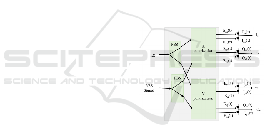
Figure 1 shows the configuration of a generic po-
larization diversity coherent receiver, wherein two
single-polarization receivers are combined. First, the
incoming RBS signal with an arbitrary SOP is
separated into two linear polarization components,
these having the same frequency as the LO light with
a polarization beam splitter (PBS); I
x,
Q
x,
I
y,
and
Q
y
are
the photocurrent outputs of the four balanced
detectors. Balanced photodetector (BPD) output
retains only alternating current signals while
removing direct current signals.
Figure 1: Generic configuration of polarization diversity
hybrid with balanced photodiodes (90° Optical Hybrid
Manual).
The complex electric field of the RBS signal in φ-
OTDR is expressed as:
E
(
t
)
=A
(
t
)
exp{j(⍵
t+
θ
(
t
)
+
θ
(
t
)
)}
(1)
where A
s
(t), ω
s
, and θ
s
(t) are the complex amplitude,
angular frequency, and the initial phase of the signal,
respectively. The term θ(t) stands for the phase
change induced by perturbations along the fiber.
Similarly, the complex electric field of the LO
used as a reference at the receiver can be written as:
E
(
t
)
=A
(t)exp {j⍵
t+
θ
(
t
)
} (2)
PHOTOPTICS 2025 - 13th International Conference on Photonics, Optics and Laser Technology
50

where A
l
(t), ω
l
, and θ
l
(t) are the complex amplitude,
the angular frequency, and the phase of the local
oscillator, respectively.
The incoming signal having an arbitrary SOP is
separated into two linearly polarized components
(along the x and y axes with a PBS, which are equally
split into two arms by the 90-degree optical hybrid,
and the corresponding light field becomes:
E
,
(
t
)
=
1
2
A
,
(
t
)
exp j{(⍵
t+
θ
(
t
)
+
θ
(
t
)
)}
(3)
where E
sx,y
(t) and A
sx,y
(t) are the complex electric
field and amplitude of the transmitted signal of both
polarizations respectively. E
sx,y
(t) represents the
complex electric field of the signal in the x and y
polarization (E
sx
(t) and E
sy
(t)) and the coefficient ½
comes from the equal splitting of the signal.
The LO signal is also split into two arms, one of
which is phase-shifted by 90◦ resulting in (Wang et
al., 2016):
1
2
A
,
(
t
)
expj
⍵
t+
θ
(
t
)
+
π
2
=
1
2
jE
,
(
t
)
(4)
where E
lx,y
(t) and A
lx,y
(t) are the complex electric
field and amplitude of LO in both polarizations
respectively.
Each branch of the LO signal is coupled with the
respective branch of the RBS signal giving rise to the
eight outputs of the PDH:
E
,
(
t
)
=
1
2
√
2
(E
,
(
t
)
+E
,
(t))
E
,
(
t
)
=
1
2
√
2
(E
,
(
t
)
−E
,
(t))
E
,
(
t
)
=
1
2
√
2
(E
,
(
t
)
+jE
,
(t))
E
,
(
t
)
=
1
2
√
2
(E
,
(
t
)
−jE
,
(t))
(5)
The beating at BPDs (Bielecki et al., 2022) can
then be written as:
I
,
(
t
)
=
R
8
[(A
,
(
t
)
)
+(A
,
(t))
+2A
,
(
t
)
A
,
(t)cos
{
(
⍵
−⍵
)
t
+
(
θ
(t) − θ
(t)
)
+θ
(
t
)
}
]
I
,
(
t
)
=
R
8
[(A
,
(
t
)
)
+(A
,
(
t
)
)
−2A
,
(
t
)
A
,
(t)cos
{
(
⍵
−⍵
)
t
+
(
θ
(t) − θ
(t)
)
+θ
(
t
)
}
]
(6)
where R is the responsivity of all detectors, which is
assumed to be the same.
The balanced photodetectors can detect small
differences in optical power between two optical
input signals while largely suppressing any common
fluctuations of the inputs. With the help of BPD, the
DC signals can be filtered out and
the resulting RF
signal can be expressed as:
I
,
(
t
)
=I
,
(
t
)
−I
,
(
t
)
=
R
4
A
,
(
t
)
A
,
(t)cos{
(
⍵
− ⍵
)
t
+
(
θ
(t) −
θ
(t)
)
+
θ
(
t
)
}
(7)
Similarly, applying equations (6) and (7) for the
quadrature component we obtain:
Q
,
(
t
)
=
R
4
A
,
(
t
)
A
,
(t)sin{
(
⍵
−⍵
)
t
+
(
θ
(t) −
θ
(t)
)
+
θ
(
t
)
}
(8)
In our experiment, the input to the LO part of the
hybrid is the time-delayed replica of the one at the
signal input, namely:
E
(
t
)
=A
(t)exp {j⍵
.
(
t−τ
)
+
θ
+
θ
(
t−τ
)
}
(9)
Appling equation (9) for equations (7) and (8):
I
,
(
t
)
=
R
4
A
,
(
t
)
A
,
(
t
)
cos
{
φ
(
t
)
+ φ
}
Q
,
(
t
)
=
R
4
A
,
(
t
)
A
,
(t)sin{φ(t)
+φ
}
(10)
where φ(t) is the detected phase change due to
external vibration and φ
c
is the constant phase change
due to the delaying interferometer and it can be
removed when subtracting phases of two certain
positions.
Subsequently, the distributed phase is calculated
from the I/Q components of each polarization axis so
that:
φ
=tan
(
Q
I
)
(11)
Implementing the phase unwrapping algorithm on
the output of the arctan function extends the
demodulated phase range from negative infinity to
positive infinity. The differential phase with respect
to an adjacent point in the fiber was used to measure
the phase change induced by vibrations.
Phase Combining Strategies for Polarization-Independent Demodulation in a DAS Using Homodyne Detection with Delayed Self-Mixing in
a Non-Stabilized Mach-Zehnder Interferometer
51
Δφ = φ
(
t
)
−φ
(
t
)
(12)
Conventional polarization-diversity phase
measurement schemes assume that the contributions
of the fast and slow axes of polarization to the phase
extraction are the same, and the phase is obtained by
combining the contributions from the two with equal
weight. However, the signals in both axes could differ
in terms of SNR values in both the in-phase and
quadrature as well as the visibility of the amplitude of
the backscattering traces. Hence new strategies that
take into account these parameters for each
measurement round could be devised. In this
contribution, we employ the tracking of the relative
SNR of the in-phase component of each polarization
axis and the mean interference visibility of the
amplitude at the far end of the fiber which is used for
determining a suitable contribution strategy.
Specifically, we use percentage ratios of the relative
SNR and visibility terms to weigh the contribution of
each axis to the calculated phase or select the phase
of the one that has a better SNR in its in-phase
component. We compare the results with the
conventional approach and conclude that these
algorithms help to detect very low-intensity
vibrations at the far end of the fiber with minimal
post-processing in the presence of fading, with
selection of the phase contribution from the axis with
higher SNR yielding a relatively better result.
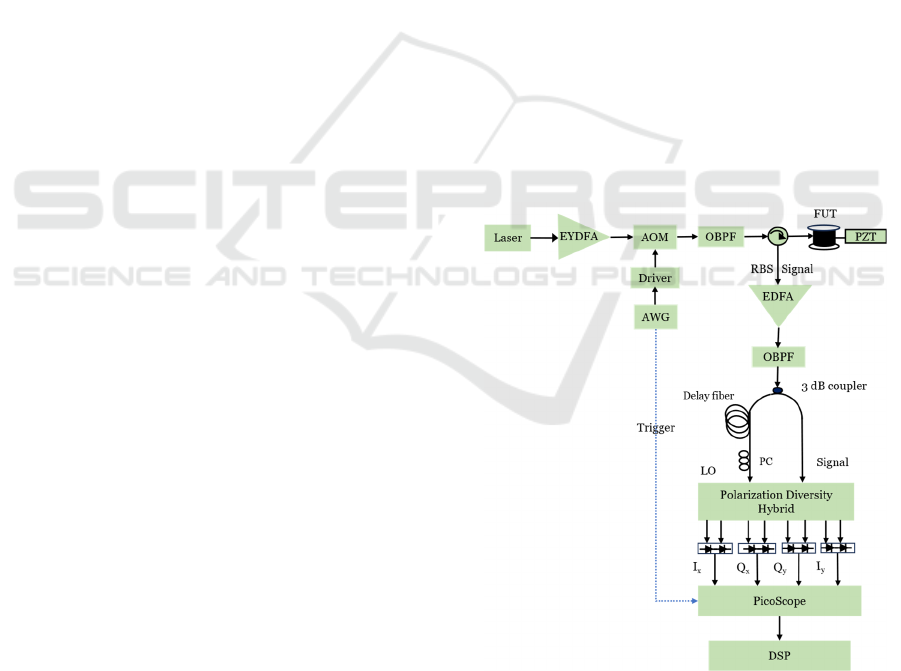
3 EXPERIMENTAL SETUP
The experimental setup of the φ -OTDR based on the
polarization diversity hybrid scheme is shown in Fig-
ure 2.
The continuous-wave light emitted by a narrow
linewidth laser source operating at 1550 nm and with
a linewidth of 100 Hz was amplified by an erbium-
ytterbium doped fiber amplifier (EYDFA) and
injected into an acoustic-optic modulator (AOM) to
generate a pulsed light. An arbitrary waveform
generator (AWG) is then used to generate pulses
having a width of 100 ns and a repetition rate of 8.33
kHz. A 1.2 nm linewidth optical bandpass filter
(OPBF) with an operating wavelength from 1530 nm
to 1560 nm suppresses the EYDFA's amplified
spontaneous emission (ASE) noise. The amplified
pulses are then launched through a three-port
circulator into the fiber under test (FUT), which is a
10 km standard single-mode fiber, a short segment of
the far end is wounded around a cylinder piezoelectric
transducer (PZT) driven with a voltage amplifier
connected to a waveform generator for applying
waveforms of controlled frequency. To investigate
the ability of the proposed system to detect phase
changes in the presence of polarization fading, the
PZT was driven with voltage values close to the
minimum possible peak-to-peak input.
The RBS light was amplified and filtered by
another EDFA and bandpass filter to improve the
SNR of the signal in the presence of the optical hybrid
(which typically has an insertion loss of 7-8 dB); it
was then fed through a delayed self-mixing
interferometer using a 3 dB coupler. One arm of the
interferometer is connected to the signal port of the
polarization diversity hybrid (PDH) and the other is
delayed by a 20 m single-mode fiber and fed to the
LO of the PDH. A polarization controller (PC) is
placed at the LO input of the optical hybrid to adjust
the angle polarization in the same branch. The fiber
length used for the delay is carefully chosen so that
the back reflections of two adjacent pulses overlap
accurately.
The PDH consists of two single-polarization 90°
optical hybrids that enable the extraction of phase,
and amplitude, from a signal with any polarization.
Eight outputs of the PDH were given to the four BPDs
with a 100-MHz bandwidth. The sync output channel
of AWG is used for triggering the signal and the beat
electric signals from each BPD were sampled by a
four-channel DAQ at a sampling rate of 156 MS/s, for
subsequent processing.
Figure 2: Scheme of delayed self-mixing with polarization
diversity hybrid. EYDFA: Erbium-Ytterbium Fiber-Doped
Amplifier; EDFA: Erbium-doped Fiber Amplifier; OBPF:
Optical Band-Pass Filter; AOM: Acousto-Optic Modulator;
AWG: Arbitrary Waveform Generator; DSP: Digital Signal
PHOTOPTICS 2025 - 13th International Conference on Photonics, Optics and Laser Technology
52
Processing; FUT: Fiber Under Test; PZT: Piezoelectric
Transducer; PC: Polarization Controller.
4 EXPERIMENTAL RESULTS
AND DISCUSSIONS
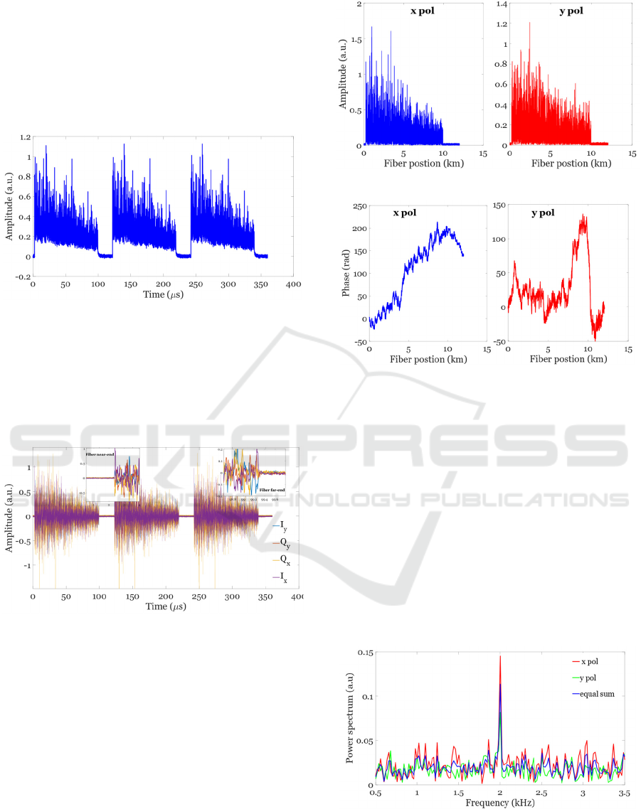
Figure 3 shows the amplified Rayleigh backscattering
traces before they are delayed and fed to the
polarization diversity hybrid, indicating that the
scheme has a high SNR of the backscattering signal.
Figure 3: Row backscattering traces before the hybrid.
Using a 3 dB coupler, the amplified RBS was fed
through a delayed self-mixing interferometer as a
signal and LO. Figure 4 shows the overlaps of the raw
I
x
, Q
x
, I
y
, and Q
y
after the PDH, proving the RBS
traces have high SNR and exhibit common-mode
noise suppression.
Figure 4: Overlapped raw traces for all 4 polarization
components.
Subsequently, a sinusoidal signal of 2 kHz was
applied to the PZT at the end of the fiber with a low
driving voltage of 40 mV peak-to-peak. After
minimal post-processing involving no averaging, the
amplitude and phase of the x and y polarization
components are reported in Figure 5 (a) and (b). The
SNRs of the two polarized signals vary with the
polarization of backscattering lights into the two input
arms of the PDH, x and y polarizations have slightly
different peak-to-peak power for both amplitude and
phase traces.
(a)
(b)
Figure 5: Demodulated responses for x and y polarization.
(a) amplitude traces (b) unwrapped phase traces.
Then, we calculated the distributed phase for each
of the fast and slow polarization axes and, for
combining to suppress fading, employed four fading-
suppression algorithms on the acquired 416 coherent
backscattering traces along the fiber. The equal sum
algorithm assumes that the contributions to the phase
of the I/Q components in the x and y polarization have
equal weights. In this case, the combined phase will
have equal contributions from both polarizations. Fig-
ure 6 shows the unwrapped phase power spectra for x
and y polarization and the one obtained with an equal
sum algorithm.
Figure 6: Comparison of unwrapped phase power spectra of
equal sum with x and y polarization.
Phase Combining Strategies for Polarization-Independent Demodulation in a DAS Using Homodyne Detection with Delayed Self-Mixing in
a Non-Stabilized Mach-Zehnder Interferometer
53
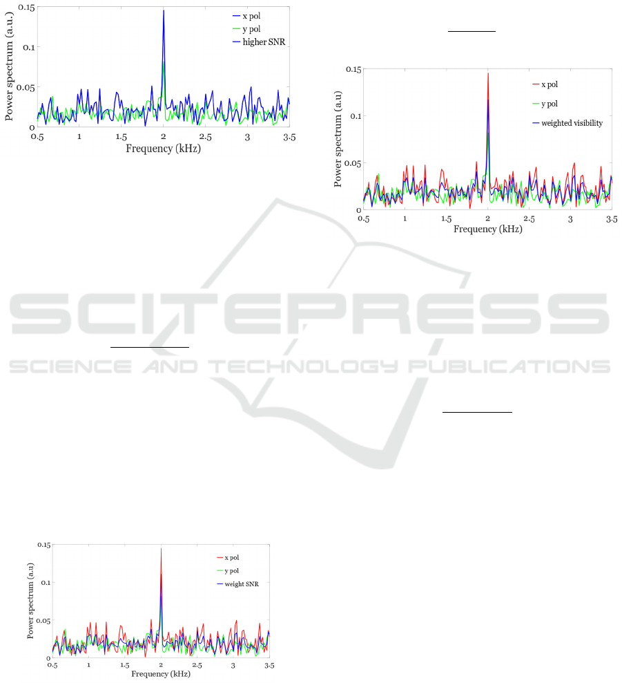
Selective higher SNR algorithm computes the
phase response from the polarization axis with higher
SNR. Figure 7 compares the selective SNR algorithm
with individual polarizations. It shows that the de-
modulated phase for x polarization has a higher SNR,
and the selective SNR algorithm uses the phase cal-
culated from this component.
Figure 7: Selective higher SNR algorithm with x and y po-
larizations.
In the weighted-SNR algorithm, first, the SNR
values of the in-phase components in the x and y po-
larization were calculated as the ratio of the RMS
value of the speckle pattern at the end of the fiber and
that of the noise floor, which represents the worst-
case scenario for the entire sensing range. Then a
multiplicative factor α is calculated as follows:
α=
SNR
SNR
+SNR
(13)
where SNR
and SNR
are the SNR of the in-
phase components of both polarizations. Then the in-
dividual values are obtained as a weighted sum of α
and (1-α) as:
SNR
=α∗Δφ
+
(
1−α
)
∗ Δφ
(14)
where Δφ
1
and
Δφ
2
are the phase changes obtained
from the I/Q components of the x- and y-polarization
axes. Figure 8 shows the comparison of phase-
weighted SNR with x and y polarizations.
Figure 8: Phase obtained using weighted-SNR algorithm
with x and y polarization.
Given the visibility in the amplitude traces is al-
ways higher than the visibility of the phase, we can
calculate the multiplicative factor from the amplitude
traces. The last algorithm called weighted-visibility is
based on the computation of alpha visibility (α
v
)
which is the ratio of the net visibility for a segment of
fiber at the far end as shown in Figure 9 and is calcu-
lated as:
α
=
χ
χ
+χ
(15)
Figure 9: Phase-weighted visibility SNR algorithm with x
and y polarizations.
The weighed visibility χi for each polarization
of the backscattering signal for a short span at the end
of the fiber was calculated by first dividing the end of
the fiber into discrete bins and computing the mean of
the interference visibility χn calculated for each bin
as:
χ
=
Ai
Ai
(16)
where Ai
max
and Ai
min
are the minimum and max-
imum values of the amplitudes of the backscattering
signals within each bin. Thus, as opposed to just hav-
ing a single visibility value, is done to have the best
possible representation of visibility, thereby avoiding
the possibility of one extreme case of execution of the
speckle pattern resulting in a wrong evaluation of the
relative visibility for both polarizations.
A comparison of the performance of the four com-
bining algorithms for polarization-diversity phase de-
modulation in the 𝜑-OTDR system is depicted in Fig-
ure 10. It is seen that all algorithms help suppress the
effect of fading, the higher SNR selective algorithm
yields a comparatively better location and phase
change detection in the vicinity of the applied disturb-
ance. In addition to confirming the computation and
monitoring of the SNR and visibility of the amplitude
of the backscattering at the end of the fiber being crit-
ical to fading-suppressed phase change detection, our
PHOTOPTICS 2025 - 13th International Conference on Photonics, Optics and Laser Technology
54

analysis points to the choice of the strategy of choos-
ing the polarization axes yielding higher SNR in the
in-phase component as being promising as it also en-
tails lowest computational cost among the algorithms
considered.
Comparing the performance of four combining al-
gorithms for polarization-independent measurements
in the 𝜑-OTDR system, the performance of the selec-
tive higher in-phase SNR algorithm is optimal. Note
that the selection of the phase contribution is made
solely based on which axis has a high SNR in its in-
phase component in a single measurement round of
416 traces spanning an interval of 50 ms. The phase
change calculated from the I/Q components in that
cycle was used to retrieve the vibration response This
algorithm also has the lowest computational cost
among the four algorithms. Thus, it is recommended
in 𝜑-OTDR systems with high dynamic performance.
Figure 10: The responses of the four algorithms at the vi-
bration of 2 kHz with respect to those of x and y polariza-
tions.
5 CONCLUSIONS
In summary, we have proposed and experimentally
demonstrated polarization fading mitigation in DAS
based on homodyne detection in an unbalanced inter-
ferometer using delayed self-mixing of the Rayleigh
backscattering traces. The technique has been used to
measure small vibrations at the end of a 10-km fiber
with vibration frequencies of 2 kHz. We have com-
pared the use of four strategies to combine the demod-
ulated phase obtained from the I/Q components of the
fast and slow polarization axes. Experimental results
show that, while phase combining strategies involv-
ing equal summation of the phase response and their
weighing using interference visibility help to mitigate
polarization fading, the selection of the phase com-
puted from the polarization component with higher
SNR in the in-phase component yields better results
as well as being the one requiring fewer computa-
tions. This approach is also more suitable for real-
time measurements compared to those based on
weighing the phase contributions or relative SNR of
the in-phase component and the relative visibility of
the amplitude of backscattering traces in both axes.
REFERENCES
90° Optical Hybrid. Website: https://www.ixblue.com/
photonics-space/90-optical hybrid/.
Bielecki, Z., Achtenberg, K., Kopytko, M. E., Mikołajczyk,
J. A., Wojtas, J., & Rogalski, A. W. (2022). Review of
photodetectors characterization methods. Bulletin of the
Polish Academy of Sciences, Technical Sciences, 70(2).
Cammarata, S., Velha, P., Palla, F., Di Pasquale, F.,
Saponara, S., & Faralli, S. (2022). 30 Gb/s NRZ Trans-
mission with Lumped-Element Silicon Photonic Mach-
Zehnder Modulator. 2022 IEEE Photonics Conference
(IPC), 1–2.
Demise, A., Di Pasquale, F., & Muanenda, Y. (2023). A
compact source for a distributed acoustic sensor using
a miniaturized EYDFA and a direct digital synthesis
module. SPIE Future Sensing Technologies 2023,
12327, 368–374.
Demise, A., Di Pasquale, F., & Muanenda, Y. (2024). A
Compact DAS Based on a Low Phase Noise DDS and
Mini-EYDFA for Real-Time Vibration Measurements.
2024 IEEE Sensors Applications Symposium (SAS), 1–
6.
Jin, Z., Chen, J., Chang, Y., Liu, Q., & He, Z. (2024). Sili-
con photonic integrated interrogator for fiber-optic dis-
tributed acoustic sensing. Photonics Research, 12(3),
465–473.
Li, Y., Wang, Y., Xiao, L., Bai, Q., Liu, X., Gao, Y., Zhang,
H., & Jin, B. (2022). Phase Demodulation Methods for
Optical Fiber Vibration Sensing System: A Review.
IEEE Sensors Journal, 22(3), 1842–1866. IEEE Sen-
sors Journal.
Liu, S., Yu, F., Hong, R., Xu, W., Shao, L., & Wang, F.
(2022). Advances in phase-sensitive optical time-do-
main reflectometry. Opto-Electronic Advances, 5(3),
200078–1.
Muanenda, Y. (2018). Recent Advances in Distributed
Acoustic Sensing Based on Phase-Sensitive Optical
Time Domain Reflectometry. Journal of Sensors,
2018(1), 3897873.
Nur, A., & Muanenda, Y. (2024). Design and Evaluation of
Real-Time Data Storage and Signal Processing in a
Long-Range Distributed Acoustic Sensing (DAS) Us-
ing Cloud-Based Services. Sensors, 24(18), Article 18.
Rao, Y., Wang, Z., Wu, H., Ran, Z., & Han, B. (2021). Re-
cent Advances in Phase-Sensitive Optical Time Do-
main Reflectometry (Ф-OTDR). Photonic Sensors,
11(1), 1–30.
Phase Combining Strategies for Polarization-Independent Demodulation in a DAS Using Homodyne Detection with Delayed Self-Mixing in
a Non-Stabilized Mach-Zehnder Interferometer
55

Shaheen, S., Hicke, K., & Krebber, K. (2023). Phase-sensi-
tive optical time domain reflectometry based on geo-
metric phase measurement. Scientific Reports, 13(1),
2862.
Stowe, D. W., Moore, D. R., & Priest, R. G. (1982). Polar-
ization Fading in Fiber Interferometric Sensors. IEEE
Transactions on Microwave Theory and Techniques,
30(10), 1632–1635. IEEE Transactions on Microwave
Theory and Techniques.
Uyar, F., Onat, T., Unal, C., Kartaloglu, T., Ozbay, E., &
Ozdur, I. (2019). A direct detection fiber optic distrib-
uted acoustic sensor with a mean SNR of 7.3 dB at
102.7 km. IEEE Photonics Journal, 11(6), 1–8.
Wang, Z., Zhang, L., Wang, S., Xue, N., Peng, F., Fan, M.,
Sun, W., Qian, X., Rao, J., & Rao, Y. (2016). Coherent
Φ-OTDR based on I/Q demodulation and homodyne
detection. Optics Express, 24(2), 853–858.
Yang, G., Fan, X., Wang, S., Wang, B., Liu, Q., & He, Z.
(2016). Long-range distributed vibration sensing based
on phase extraction from phase-sensitive OTDR. IEEE
Photonics Journal, 8(3), 1–12.
Zhang, M., Wang, S., Zheng, Y., Yang, Y., Sa, X., &
Zhang, L. (2016). Enhancement for Φ-OTDR perfor-
mance by using narrow linewidth light source and sig-
nal processing. Photonic Sensors, 6(1), 58–62.
PHOTOPTICS 2025 - 13th International Conference on Photonics, Optics and Laser Technology
56
