
On the Generation of Input Space Model for Model-Driven
Requirements-Based Testing
Ikram Darif
1 a
, Ghizlane El Boussaidi
1 b
, S
`
egla Kpodjedo
1 c
, Pratibha Padmanabhan
1
and Andr
´
es Paz
2 d
1
Department of Software and IT Engineering,
´
Ecole de Technologie Sup
´
erieure, Montreal, Canada
2
MANNARINO Systems & Software, Inc., Montreal, Canada
Keywords:
Input Space Model, Model-Driven Engineering, Requirement-Based Testing, Templates, Safety Critical
Systems.
Abstract:
Safety Critical Software (SCS) are characterized by their complex specifications with a high number of require-
ments due to their certification constraints. For such systems, requirements can be specified semi-formally
using Controlled Natural Language (CNL) to mitigate the inherent ambiguity of natural language, and to be
understandable by certification agents. Requirements serve as artifacts for software testing, where Combina-
torial Interaction Testing (CIT) emerges as a relevant testing technique for SCS. CIT requires as a first step the
generation of an Input Space Model (ISM) from input specifications. In this paper, we propose an approach
that leverages Model-Driven Engineering (MDE) techniques for the generation of ISM from semi-formal CNL
requirements constrained by templates that are specified by template models. To automatically generate the
ISM, we define rules that map the template models to a generic input space model. The generated ISMs in-
clude test parameters, their test values, and inter-input constraints. Our approach ensures traceability between
the generated ISM and the originating requirements, which is crucial for the certification of SCSs. We im-
plemented our approach, and we evaluated it through a case study from the avionics domain. The case study
shows that our approach can support the DO-178C certification needs in terms of requirements-based testing
and provides multiple advantages over manual modeling.
1 INTRODUCTION
Safety Critical Softwares (SCS) are engineered for
the safety of critical systems, where a failure can re-
sult in catastrophic results (Leveson, 1995). Given
their critical nature, they are required to comply with
numerous regulations and standards to demonstrate
their safety. SCS are characterized by their complex
specifications with a high number of requirements.
This arises from their certification constraints, and
their need to carefully address a wide range of risks
to avoid errors. Generally, requirements are speci-
fied in Natural Language (e.g., English). However,
dealing with informal specifications is tedious and
error prone. On the other hand, formal languages
add an overhead to the development life-cycle due
a
https://orcid.org/0009-0002-2646-4471
b
https://orcid.org/0000-0001-6145-774X
c
https://orcid.org/0000-0001-5224-9658
d
https://orcid.org/0000-0002-0743-769X
to the time and efforts to learn them. In the con-
text of SCS, requirements need to be understand-
able by non-experts and certification agents, but also
amenable to automated analysis. For that, Controlled
Natural Language (CNL) is used. CNLs are devel-
oped from a base language, by constraining its syn-
tax and semantics while preserving its natural prop-
erties (Kuhn, 2014). This is usually enforced using
templates with fixed and variable parts. We recently
proposed and applied a template-based approach in
an research project with an industrial partner from
the avionics domain, which is developing an SCS that
is to be certified according to the ARINC-653 (SAE,
2015) and DO-178C (for Aeronautics (RTCA), 2011)
standards. The present work is a proposal that builds
on template models to support software testing.
Software testing is a crucial activity of the soft-
ware development life-cycle, whose primary goal is
to identify errors by comparing the behavior exhib-
ited by the software during testing with its expected
behavior (Ammann and Offutt, 2016) as specified
250
Darif, I., El Boussaidi, G., Kpodjedo, S., Padmanabhan, P. and Paz, A.
On the Generation of Input Space Model for Model-Driven Requirements-Based Testing.
DOI: 10.5220/0013186800003896
In Proceedings of the 13th International Conference on Model-Based Software and Systems Engineering (MODELSWARD 2025), pages 250-262
ISBN: 978-989-758-729-0; ISSN: 2184-4348
Copyright © 2025 by Paper published under CC license (CC BY-NC-ND 4.0)

through requirements. A relevant approach in the
context of SCS is Combinatorial Interaction Testing
(CIT), which focuses on the generation of efficient
test suites, based on the interaction of multiple pa-
rameters (IEEE, 2022). CIT initiates with the process
of modeling, where parameters and their value do-
main are modeled, resulting in the creation of an Input
Space Model (ISM). An ISM is a representation of the
input space of the System Under Test (SUT) through
test parameters, their test values, and constraints.
Multiple Requirements-based ISM generation ap-
proaches have been proposed in literature, with some
supporting informal requirements (e.g., (Poon et al.,
2013)), others supporting formal languages (e.g.,
parametric timed automata (Luthmann et al., 2019)),
and yet other supporting semi-formal requirements
(e.g., feature models (Calvagna et al., 2013; Johansen
et al., 2012)). However, none of these approaches uti-
lize semi-formal CNL requirements for ISM genera-
tion. Additionally, none of them addresses the certi-
fication needs of safety-critical systems, and most of
them do not provide tool support.
In this paper, we build on our previous work on
template models for requirements (Darif et al., 2023)
to propose an approach for the generation of ISM
from semi-formal CNL requirements. The proposed
approach exploits model-driven technologies to build
on models of requirements templates, and defines
rules that map those models to a generic input space
model. Those mapping rules are then used to generate
an ISM from a set of requirements created using the
template models. The approach includes three stages,
namely (1) Planning where the aspects to be mod-
elled are identified, along with the input specification
(i.e., requirements) to be used for the generation, (2)
Preparation where requirements are specified using
the set of templates to prepare them for the genera-
tion, and (3) Modelling where test parameters, their
test values, and constraints are generated by applying
the mapping rules. Our approach ensures traceabil-
ity between the generated test cases and the require-
ments/conditions from which they are extracted. This
eases the computation of requirements and conditions
coverage, plus the identification of incorrect and in-
complete implementation of functionalities. Also, it
reduces the dependence on the tester’s domain knowl-
edge. We implemented our approach into the MD-
RSuT tool, for the automated generation of ISM files
from specifications. Thus making the testing process
more time-efficient and less error-prone.
We evaluated our approach through a case study
on the ARINC-653 standard from avionics, covering
around 200 requirements. The goal was to evalu-
ate our approach’s compliance with certification con-
straints, and compare the generated ISMs to those
manually created. Our results show that the approach
aligns with DO-178C certification constraints, and it
provides multiple benefits over manual modeling.
The remainder of the paper is organized as fol-
lows. section 2 presents the related work. section 3
details our approach along with illustrative examples,
and it presents our implementation. section 4 de-
scribes our evaluation of the approach, and the ob-
tained results. section 5 discusses the benefits, limi-
tations, and threats to validity. Finally, section 6 con-
cludes our paper and presents our future work.
2 RELATED WORK
Multiple approaches were proposed to support ISM
generation from requirements. Some papers, such as
(Grindal and Offutt, 2007) propose general guidelines
and strategies to derive ISMs from specification doc-
uments. Others, like the current paper, extend and
build upon it. For instance, (Tsumura et al., 2016)
examined database schemas, business logic and SQL
scripts to extract the inputs (i.e. database columns)
and constraints in the ISM and then analyzed require-
ments documents to identify the corresponding in-
put spaces. (Preeti et al., 2017) also followed the
basic methodology and propose a rule-based semi-
automatic approach to generate ISM elements from
use case specifications and UML use case diagrams.
The proposed approach uses a combination of user in-
puts and system inputs. The modelling considered the
execution flows of use cases; therefore requiring the
modelling of both types of data inputs.
Approaches that extend the basic methodology
typically include additional constructs to capture ad-
ditional characteristics considered during testing. For
instance, in (Farchi et al., 2014) they introduce the
concept of order and padding to account for different
input orderings within the ISM. In (Johansen et al.,
2012), they introduce weight assignments to prod-
uct features, which are inputs for ISMs in a con-
text of software product lines. The weights represent
the number of product instances where the feature is
present in a market. They prioritize certain features
during the sampling phase. In (Calvagna et al., 2013),
they propose an approach that translates feature mod-
els into ISMs handled in CITLAB. They introduce an
additional step in the modelling phase to reduce the
number of unnecessary inputs and constraints.
Few existing approaches take as input semi-
formal requirements (e.g., feature models (Johansen
et al., 2012; Calvagna et al., 2013), use cases (Preeti
et al., 2017), and Given When Then (GWT) frame-
On the Generation of Input Space Model for Model-Driven Requirements-Based Testing
251
work (De Biase et al., 2024)). For instance, (De Biase
et al., 2024) propose an approach that semi-automates
the completion of SysML state machine models from
requirements expressed using the GWT framework.
However, to the best of our knowledge, there are no
approaches that support ISM generation from CNL
specifications. The majority of approaches are not
supported by automated tools, and do not address the
certification needs for SCS. Additionally, very few
works propose approaches solely based on require-
ments and typically require additional source of in-
formation beyond specification artifacts.
3 AN APPROACH FOR ISM
GENERATION
To tackle the challenges faced by our industrial part-
ner, we propose an approach for ISM generation
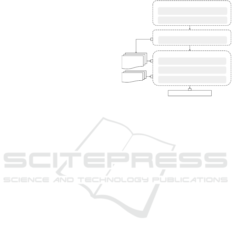
based on CNL requirements. A high-level view of the
approach is depicted by Figure 1. At the core of our
approach is the use of templates and model-driven en-
gineering to support the specification of requirements
and the generation of the ISM. The approach com-
prises three stages, namely (1) Planning where the as-
pect(s) of the SUT to be modeled are identified, and
relevant requirements are gathered, (2) Preparation
where requirements are specified using templates, and
(3) Modeling where input parameters, their test values
and constraints are identified.
Our approach is model-driven, that is: (1) the tem-
plates used to specify requirements within the prepa-
ration phase are represented by template models, and
(2) the ISM generated within the modeling stage is
represented by a generic ISM model. The modelling
stage is performed by applying mapping rules that
link elements of the template models to correspond-
ing elements of the ISM model. As Figure 1 shows,
the modelling stage takes as inputs the requirements
specified through the preparation phase, and the tem-
plate models. The mapping rules are then applied to
generate the ISM for the SUT.
Our approach extends the basic methodology for
ISM generation (i.e., identifying the inputs, their
value domains, and their interactions) by adding plan-
ning and preparation stages where we gather relevant
source information of the aspects of SUT, and we pre-
pare them for the modeling. Our approach adopts
Functionality-based modeling as we use the specifi-
cation (i.e., requirements) as an input of the modeling
process. Additionally, our approach supports trace-
ability between the test cases included in the ISM and
the requirements from which they were generated.
For our industrial partner, this traceability is espe-
Planning
1. Identifying the aspects of the SUT to be modeled
2. Gathering relevant requirements
Preparation
3.Representing requirements using the templates
Modeling
4. Identifying test parameters
5. Determining test values
6. Identifying inter-input constraints
Input space model for the SUT
Requirements
specified using
the templates
Mapping
rules
Figure 1: The ISM generation approach.
cially important as it is required to comply with the
DO-178C standard (for Aeronautics (RTCA), 2011).
The following subsections describe in detail the
three stages of the approach. Subsections 3.1 and 3.2
describe the planning and preparation phases, respec-
tively. Subsection 3.3 describes the modelling phase.
In particular, it describes the templates used for speci-
fying requirements, their models and their mapping to
a generic ISM model. Throughout these subsections,
we use requirements extracted from the ARINC-653
specification (SAE, 2015) to illustrate the approach.
Subsection 3.4 briefly describes the implementation
of the approach.
3.1 Planning
Although planning was not explicitly discussed
within literature, it is necessary to prevent inadequa-
cies within the generated ISMs. For instance, in (Yuan
et al., 2011; Chandrasekaran et al., 2017; Wojciak
and Tzoref-Brill, 2014), the generated ISMs missed
some known faults, reducing their suitability for test-
ing. This was due to planning issues, which led to
missing inputs. In this regard, we define a Planning
stage as the first activity of our approach.
Having a better understanding of the aspects of the
SUT leads to the generation of more adequate ISMs
(Andrzejak and Bach, 2018). For that, the goal of the
first step of planning (Figure 1) is to determine the
aspect(s) of the SUT to be modelled. This includes
the testing scope and objectives. For instance, within
the ARINC-653 standard (SAE, 2015), there is a unit
called the health monitor (HM) that is responsible for
handling errors at different levels. An error could be
of module, partition, or process level. In this case, one
objective could be to test the functionality of the HM
MODELSWARD 2025 - 13th International Conference on Model-Based Software and Systems Engineering
252

handling partition-level errors. We will use this case
to illustrate the steps of our approach.
Within the second step of Planning, the goal is to
gather necessary sources that are relevant for the iden-
tified aspects of the SUT, from which the information
driving the modelling will be drawn. As we follow
a requirements-based testing approach, the inputs to
the approach are a set of requirements. Requirements
may vary in their rigour. However, in the context of
SCS, it is required for the specification to have a high
level of rigour, for instance by explicitly specifying
the robustness requirements to support negative test-
ing in order to comply with certifications. For our er-
ror handling example, we gathered requirements from
the ARINC-653 specification (SAE, 2015). Table 1
expresses two of those requirements. The first one
specifies what the OS should do if a partition-level er-
ror occurs under a set of conditions, while the second
defines the behavior of an HM operation.
3.2 Preparation
It is important to represent the requirements in a man-
ner that facilitates information handling and extrac-
tion. Requirements can be specified using different
languages with various levels of formality. Generally,
requirements are specified using Natural Language
(NL) such as English, especially in the context of SCS
due to certification constraints. However, using NL
results in requirements that are ambiguous, incom-
plete, and not amenable to automated analysis. For
that, we adopt Controlled-Natural Language (CNL)
templates for specifying requirements. A CNL pro-
vides discipline to NL requirements by constraining
the syntax, lexicon, and semantics of a base language
(e.g., English). This is supported by the use of tem-
plates with fixed parts and placeholders to be filled.
In this regard, the preparation stage of our ap-
proach includes the specification of requirements us-
ing the templates presented in (Darif et al., 2023). We
chose these templates as they were specifically de-
veloped to support our industrial partner. In (Darif
et al., 2023), seven templates were proposed, covering
two categories of requirements: 1) functional require-
ments describing the functionalities/behaviour of the
system, and 2) data requirements defining the compo-
nents, attributes, and types of the system. The latter
serve as a dictionary for functional requirements. The
templates for functional requirements are divided into
two types: 1) Operational Behavior Requirements
(OBR) template that describes the behavior of the sys-
tem under specific conditions, and 2) Service Behav-
ior Requirements (SBR) template that describes the
behavior of a service (i.e., a function). Both OBRs
and SBRs use the same templates for conditions.
The templates for data requirements are divided
into five types: 1) Simple Type Definition Require-
ments (STDR) templates that define simple types,
2) Composite Type Definition Requirements (CTDR)
templates that define composite types, i.e., types that
are defined through parameters, 3) Data Definition
Requirements (DDR) templates that define parame-
ters of the system, 4) Service Interface Definition Re-
quirements (SIDR) templates that define the input and
output parameters of a service, and 5) Data Interaction
Requirements (DIR) templates that define dependen-
cies between parameters. The templates are described
in (Darif et al., 2023).
Consider the example of the requirements in-
cluded in Table 1. We used the OBR template to spec-
ify Rq1, while we used the SBR to specify Rq2. All
parameters used within these requirements (e.g., SYS-
TEM STATE) were specified using the DDR template,
and their types were specified using STDR template
(e.g., SYSTEM STATE TYPE). Using these templates
ensures the specification of complete and correct re-
quirements. This increases the efficiency of the mod-
elling process and it eases its application as require-
ments include complete and concrete information.
3.3 Modeling
Given the template models that formalize the struc-
ture of the requirements, we defined a generic ISM
model and mapping rules that link elements of the
template models to elements of the generic ISM
model. A mapping rule describes how some elements
of the ISM can be generated from elements of the tem-
plate models. These rules are used to generate an ISM
from requirements that comply with the templates.
Recall that the ISM represents the input space of
the SUT through three elements: 1) test parameters
that exercise the system behavior, 2) the test values
that test parameters take, and 3) constraints specify-
ing the value combinations that cannot occur simul-
taneously. Therefore, the Modeling stage includes
three steps (i.e., steps 4 through 6 in Figure 1) where
each of these elements is identified from input re-
quirements. This identification is performed through
mapping rules that map: 1) the conditions template
model to test parameters of the ISM model, 2) data
definition template model to test values of the ISM
model, and 3) the data interaction template model to
constraints of the ISM model. In the following we
present the template models, the ISM model, and the
mapping rules used for the identification.
On the Generation of Input Space Model for Model-Driven Requirements-Based Testing
253

Table 1: Examples of requirements, their corresponding template, and generated ISM.
ID Requirement Template Generated ISM
Rq1 When
An error is reported to the health monitor,
If
SYSTEM STATE is equal to PARTITION
EXECUTION
ERROR LEVEL of the error in the Multi-partition-
HM table is equal to PARTITION
The error handler process is not created
Then
The OS shall apply the partition level error recovery
action of the error in the Partition HM table
When
<subject> <action verb> <adverb> <object>
If
<parameter name> is equal to <value>
<parameter name> of <entity> is equal to
<value>
<object> <action verb>
Then
<subject> shall <action verb> <object>
<details>
Parameter Name: Error Reported to Health Monitor, Pa-
rameter Abstraction: event, Requirement ID: R1, Condi-
tion: R1 C1, Values: true, Value Abstraction Level: char-
acteristic.
Parameter Name: SYSTEM STATE, Parameter Abstrac-
tion: Data input, Data Type: Enumeration, Require-
ment ID: R1, Condition: R1 C2, Values: PARTI-
TION EXECUTION, Value Abstraction Level: value.
Parameter Name: Multi-
partition HMtable.ERROR LEVEL Parameter Abstrac-
tion: Data input, Data Type: Enumeration, Requirement
ID: R1, Condition: R1 C3, Values: PARTITION, Value
Abstraction Level: value.
Parameter Name: Error Handler Process, Parameter Ab-
straction: object, Requirement ID: R1, Condition: R1 C4,
Values: NOT CREATED, Value Abstraction Level: char-
acteristic.
Rq2 When the REPORT APPLICATION MESSAGE
service is called
with the following parameter conditions:
LENGTH is within [0,128] range
The OS shall perform the following actions:
1. Transmit the error to the health monitor function
2. Set RETURN CODE to NO ERROR
When the <service name> service is called
with the following parameter conditions:
<parameter name> is within [<minimum
value> , <maximum value>] range
The <entity> shall perform the following actions:
1. <action verb> <object> <details>
2. Set <parameter name> to <value>
Parameter Name: LENGTH, Parameter Abstraction: data
input, textbfData Type: Numeric, Requirement ID: R2, Con-
dition: R2 C1, Values: 0, 1, 127, 128, Value Abstraction
Level: value.
3.3.1 Template Models
The template models used in the modelling stage are:
the conditions template model, the data definition
model, the simple type definition model, and the data
interaction model. These template models are repre-
sented as UML class diagrams as shown in Figure 2.
There are three categories of conditions that can be
used as part of functional requirements:
• Value-State Conditions. They describe constraints
related to a parameter. They can be either (1)
value-related conditions if they describe a param-
eter being equal to, less than, or greater than a
certain value, or (2) range-related conditions if
they describe a parameter within or outside a cer-
tain range. These are both defined by the pa-
rameter name, the comparison criteria, and the
value/range to which the parameter is compared.
• Action-Driven Conditions. They describe an en-
tity performing either a continuous or a discontin-
uous action that can trigger another action. They
can either be continuous or discontinuous action
driven conditions depending on the nature of the
action. They are defined through a subject, an ac-
tion verb, and an object. Continuous action-driven
conditions are not covered by our approach.
• Event-Driven Conditions. They describe con-
straints that are triggered by an event occurring at
a specific time. They have the same components
as action-driven conditions (e.g., subject, action
verb), the difference is the tense of the action verb
(past vs present tense).
The Data definition model describes the structure of
data definition requirements, i.e., requirements that
define parameters of the system. As Figure 2 shows,
a parameter is defined by its name, type, optional ex-
pected values, optional fixed value (if it is a constant),
optional default value, interpretation, and whether it
is a configuration parameter. The parameter types are
defined in simple type definition requirements, which
have the structure presented in the simple type def-
inition model in Figure 2. A type is defined by its
name, primitive type (e.g., numeric, enumeration),
and optional expected values (e.g., an enumeration or
a range of values). Finally, dependencies between pa-
rameters are defined through data interaction require-
ments. The data interaction model (in Figure 2) spec-
ifies that these requirements are defined by the param-
eters involved in the dependency, and one or more
constraints. Each constraint includes one or more
value-state conditions, and one value-state action.
It should be noted that the template models are
inter-dependent (as shown in Figure 2). The data defi-
nition model uses the types defined through the simple
type definition model, and both the conditions and the
data interaction models use the parameters defined
through the data definition model.
3.3.2 ISM Model
Our approach enables the generation of ISMs that
have the structure defined in Figure 3. As the figure
shows, an ISM is defined through a set of parame-
ters, their test values, and optional constraints. Within
our approach, a test parameter is defined by its name,
its abstraction type which specifies whether it is a
data input, an event, or an object, and its Data type
which specifies the type (e.g., numerical, enumera-
tion) of the parameter in case of a data input. The
Parameter abstraction type aims to clarify the nature
of the extracted parameters, whether it is a parameter
of the system (i.e., data input), an event that occurred,
MODELSWARD 2025 - 13th International Conference on Model-Based Software and Systems Engineering
254

Simple type definition requirement
SimpleTypeName : String
Type : SimpleTypeEnumeration
<<Enumeration>>
SimpleTypeEnumeration
Numeric
Alphanumeric
Alphabetic
Enumeration
ValueEnumeration
EnumerationLiteral :
String [1..*]
<<Abstract>>
Expected values
ValueRange
MinimumValue : Int
MaximumValue : Int
1
Simple type definition Model
Data definition requirement
ParameterName : String
ParameterType : String
ParameterExpectedValues : Expected values [0..1]
ParameterFixedValue : String [0..1]
DefaultValue : String [1..0]
ParameterInterpretation : String
ConfigurationData : Boolean
Data Definition Model
<<Abstract>>
Condition
ConditionalKeyWord : KeyWordType
Value-related condition
ValueComparisonCriteria :
ValueComparisonCriteriaType
Value : String
<<Abstract>>
Value-state condition
ParameterName : String
Entity : String [0..1]
Range-related condition
ValueComparisonCriteria :
ValueComparisonCriteriaType
ValueRange
MinimumValue : Int
MaximumValue : Int
Detail
DetailRange : DetailRangeType [0..1]
EntityRange : EntityRangeType [0..1]
Entity : String
<<Enumeration>>
DetailRangeType
Within
Using
For
Of
Other than
To
Between
And
With
Before
After
Without
Until
<<Enumeration>>
EntityRangeType
The
An
A
All
Each
Only one
one or more
at least one
other
1..1
<<Enumeration>>
RangeComparisonCriteriaType
Within
Out of
<<Abstract>>
Action-driven condition
ActionVerb : String
Continious
action-driven condition
Subject
EntityRange : EntityRangeType [0..1]
Entity : String
Object
Adverb : AdverbType [0..1]
EntityRange : EntityRangeType [0..1]
Entity : String
<<Enumeration>>
AdverbType
From
To
By
As
Upon
For
In
Discontinious
action-driven condition
1..11..1
0..*
<<Enumeration>>
ValueComparisonCriteriaType
is equal to
is inferior to
is superior to
1..*
Event-driven condition
ActionVerb : String
1..1
0..*
Conditions Model
Data interaction requirement
ParameterName : String [2..*]
Value-state action
Constraint
<<Abstract>>
Value-state condition
0..*
1..* 1..1
Data interaction Model
Main classes
Classes defined in
other packages
Enumerations
Figure 2: Template models.
Test parameter
ParameterName: String
ParameterAbstraction: ParameterAbstractionType
DataType: TypeOfData
RequirementID: String
ConditionID: String
Test value
Value: String [1..*]
ValueAbstractionLevel: ValueAbstractionType
Constraint
ID: String
1..*
1..*
Condition
comparisonCriteria: ComparisonCriteriaType
value: String
1..1
<<enumeration>>
ParameterAbstractionType
Data input
Object
Event
<<enumeration>>
ValueAbstractionType
Value
Partition
Characteristic
<<enumeration>>
ComparisonCriteriaType
equal to
superior to
inferior to
within
out of
1.*
Left-hand side
Right-hand side
1.* 1.1
Input Space Model
ID: String
*
Figure 3: Generic ISM model.
or an object. Event and object parameters are gen-
erally found in high-level specifications (e.g., stan-
dards) where some functionalities are implementation
dependent. In these cases, it is the tester’s responsibil-
ity to interpret them and trace them to parameters of
the system. For instance, the first condition of Rq1 (in
Table 1) specifies an event of the error being reported
to the health monitor. Therefore, the extracted test pa-
rameter has a Parameter abstraction of ”event”. The
second condition is related to the SYSTEM STATE pa-
rameter, and thus the test parameter is a ”Data input”.
To support traceability between test parameters and
the originating requirements/conditions, the test pa-
rameters are defined by the RequirementID and Con-
ditionID attributes.
Each test parameter has a test value, which repre-
sents values of the input domain that are used to test
the parameter. A test value consists of one or multi-
ple values that the parameter takes, and is associated
with a Value abstraction level. The Value abstraction
level specifies the nature of the values, which can ei-
ther be (1) Value if they specifies concrete values of
the parameter, (2) Partition if they specify a subset
of the input space, or (3) Characteristic if they spec-
ify an event or an object test parameter. We used this
abstraction level schema in conformance with the vo-
cabulary used in testing (Ammann and Offutt, 2016).
Finally, an ISM can optionally include a set of
inter-input constraints. A constraint is defined by one
or multiple left-hand conditions that specify the con-
ditions of the constraint, and a right-hand condition
that specifies the operation performed if the left-hand
condition(s) apply. Take the example of the follow-
ing constraint from an ARINC-653 ISM: ”The error
handler process caused the error -> the error handler
process is created”. It specifies that an error handler
process can only cause an error if it is already created.
3.3.3 Identifying Test Parameters and Values
We support the generation of ISMs from input spec-
ification by defining mapping rules that link the tem-
plates models to the ISM model. The high-level pro-
cedure for ISM generation is described in algorithm
1. It takes as inputs the requirements from which
the ISM will be drawn, and the template models rep-
resenting the requirements (i.e., Conditions template
model, Simple type template model, and Data Defi-
nition template model). The behavior of functional
units (i.e., the independent modules of the system that
perform specific functions) is influenced by the func-
On the Generation of Input Space Model for Model-Driven Requirements-Based Testing
255

tion’s inputs and the environmental conditions (Os-
trand and Balcer, 1988). Thus, the conditions of func-
tional requirements can be used to identify the test
parameters affecting the functionality (Ammann and
Offutt, 2016). In our case, the mapping rules use
the conditions of operational behavior requirements
and service behavior requirements to identify the test
parameters, and they exploit established test meth-
ods such as equivalence partitions and boundary value
analysis to compute the values of the parameters. As
algorithm 1 shows, we iterate through each condition
of the input functional requirements. Subsequently,
we identify the ConditionID and RequirementID for
the test parameter, and we apply the mapping rules
that correspond to the identified condition. The map-
ping rules are listed in Table 2. The table uses color
coding to indicate the elements mapped to each rule.
Input: Functional Requirements F R, Template Models T M, Data
Definition Requirements DDR, Simple Type Definition
Requirements S TDR, Data Interaction Requirements DIR
Output: Set of Parameters P
P ← {}
for each requirement R
i
∈ F R do
for each condition C
i
∈ R
i
.Condition do
P
i
.ConditionID ← ID of C
i
P
i
.RequirementID ← ID of R
i
T M
i
← getTemplateModel(C
i
, T M)
P
i
← applyMappinRules(C
i
, T M
i
, DDR, ST DR, DIR)
Add P
i
to P
end
end
return P
Algorithm 1: Main Algorithm generateISM.
As the mapping rules table indicates, the test pa-
rameters and their values are identified differently de-
pending on the type of the condition. For value-state
conditions, test parameters are defined in the same
manner, independently of the type of the condition
(value or range related). The Parameter name is the
name of the parameter within the conditions model,
optionally qualified with the entity’s name (i.e., En-
tity.ParameterName) if it is not null (R1 and R2 in
Table 2). The Data type is the type of the parameter
that is defined in the Data definition model, and Pa-
rameter abstraction is equal to ”Data Input”, i.e., it
corresponds to a parameter of the system.
The identification of test values depends on the
type of the value-state condition. For Range-related
conditions, we perform boundary analysis (R4 and
R5 in Table 2) as ranges can be relatively large, and
testing all values is challenging. Boundary analysis
refers to testing the values that are directly on, above,
and beneath the edges of the boundary (Myers and
Sandler, 2004). Selecting these values is a form of
stress testing (Ammann and Offutt, 2016). For in-
stance, Rq2 (Table 1) includes a condition where the
parameter LENGTH is within [0,128]. Thus, the test
values for the ISM will include boundary values, i.e.,
minimum value: ”0”, minimum +1: ”1”, maximum
value: ”128”, and maximum-1: ”127”. The Value ab-
straction level or range-related conditions is ”Value”.
For Value-related conditions, the Value abstrac-
tion level depends on the value assigned to the param-
eter within the the conditions template model. If the
value is part of the concrete values of the parameter
(i.e., its expected values in the Data definition model),
then the Value abstraction level is equal to ”Value”
(R6 in Table 2). Otherwise, it is equal to ”Partition”,
i.e., it does not represent a concrete value but rather
a partition (R7 in Table 2). For both cases, the pa-
rameter value depends on the type of the parameter
(e.g., enumeration or numeric) from the Simple type
model, and the comparison criterion from the con-
ditions model (R8-R13 in Table 2). For instance, if
the comparison criterion is ”not equal to” and the pa-
rameter is an enumeration, the test value is assigned
all values of the enumeration from the Simple type
model, except for the value specified in the conditions
model.
For event-driven conditions, the Parameter Name
is the occurred event (i.e., the ”Subject+ Action verb+
Object” of the conditions model), the Parameter ab-
straction is ”Event”, the Value is ”true”, and the
Value abstraction level is ”Characteristic” (R14 in
Table 2). This was the case for the first condition
of Rq1 (in Table 1), where the test parameter’s name
is ”Error Reported to Health Monitor”, which corre-
sponds to the event described in the requirement. For
discontinuous-driven conditions, the identification is
also straightforward as: the Parameter Name is the
entity on which the action is performed(i.e., the ”Ob-
ject” of the conditions model), the Parameter ab-
straction is ”Object”, the Value is the action per-
formed (i.e., ”action verb + Object” of the conditions
model), and the Value abstraction level is ”Charac-
teristic” (R15 in Table 2). The fourth condition of
Rq1 in Table 1 illustrates this case as the parame-
ter name is Error Handler Process (the object of the
condition), and the value is ”Not Created” (the action
verb of the condition).
By the end of this step, we generate an ISM that
includes the identified test parameters and values.
Some ISM examples are shown in Table 1.
3.3.4 Identifying Inter-Input Constraints
Input parameters should not be considered in isola-
tion (Kuhn et al., 2020), since the value of a parame-
ter can constrain or limit the value of another param-
eter. Inter-input constraints specify the value com-
binations that should not (or should) occur simulta-
neously. These constraints are optional in ISMs but
they can lead to significant reduction of test efforts,
MODELSWARD 2025 - 13th International Conference on Model-Based Software and Systems Engineering
256

Table 2: Mapping table.
VSC: Value-State condition
ParameterName = P
Entity = Null
TP: Test Parameter
ParameterName = P
VSC: Value-State condition
ParameterName = P
Entity = E
TP: Test Parameter
ParameterName = E.P
TP: Test Parameter
DataType = T
ParameterAbstraction = "Data input"
VSC: Value-State condition
ParameterName = P
DD: Data Definition
ParameterName = P
ParameterType = T
VRC: Value-Related condition
Value = V
DD: Data Definition
ParameterName = P
ParameterType = T
STD: Simple Type Definition
TypeName = T
STD: ValueEnumeration
EnumerationLiteral = V,Y
VSC: Value-State condition
ParameterName = P
TV: Test Value
ValueAbstraction = "Value"
VRC: Value-Related condition
Value = V
DD: Data Definition
ParameterName = P
ParameterType = T
STD: Simple Type Definition
TypeName = T
STD: ValueEnumeration
EnumerationLiteral = Y,Z
VSC: Value-State condition
ParameterName = P
TV: Test Value
ValueAbstraction = "Partition"
VRC: Value-Related condition
ValueComparisonCriteria = "equal to"
Value = V
VSC: Value-State condition
ParameterName = P
TV: Test Value
Value = V
VRC: Value-Related condition
ValueComparisonCriteria = "not equal to" /
"inferior to" / "superior to"
Value = V
VSC: Value-State condition
ParameterName = P
DD: Data Definition
ParameterName = P
ParameterType = T
STD: Simple Type Definition
TypeName = T
STD: ValueEnumeration
EnumerationLiteral = Y,Z
TV: Test Value
Value = "not equal to" /
"inferior to" / "superior to" V
VRC: Value-Related condition
ValueComparisonCriteria = "not equal to"
Value = V
VSC: Value-State condition
ParameterName = P
DD: Data Definition
ParameterName = P
ParameterType = T
STD: Simple Type Definition
TypeName = T
Type = "Enumeration"
STD: ValueEnumeration
EnumerationLiteral = V,Y,Z
TV: Test Value
Value = Y,Z
VRC: Value-Related condition
ValueComparisonCriteria = "not equal to"
Value = 5
VSC: Value-State condition
ParameterName = P
DD: Data Definition
ParameterName = P
ParameterType = T
STD: Simple Type Definition
TypeName = T
Type = "Numeric"
STD: ValueRange
MinimumValue = 1
MaximumValue = 6
TV: Test Value
Value = 1,2,6
VRC: Value-Related condition
ValueComparisonCriteria = "superior to"
Value = 3
VSC: Value-State condition
ParameterName = P
DD: Data Definition
ParameterName = P
ParameterType = T
STD: Simple Type Definition
TypeName = T
Type = "Numeric"
STD: ValueRange
MinimumValue = 1
MaximumValue = 7
TV: Test Value
Value = 3,4,6,7
VRC: Value-Related condition
ValueComparisonCriteria = "inferior to"
Value = 3
VSC: Value-State condition
ParameterName = P
DD: Data Definition
ParameterName = P
ParameterType = T
STD: Simple Type Definition
TypeName = T
Type = "Numeric"
STD: ValueRange
MinimumValue = 1
MaximumValue = 6
TV: Test Value
Value = 1,2,3,4
Value-state conditions
Value-related conditions
Condition Type
Template models
ISM model
TP: Test Parameter
ParameterName = P
TP: Test Parameter
ParameterName = P
TP: Test Parameter
ParameterName = P
TP: Test Parameter
ParameterName = P
TP: Test Parameter
ParameterName = P
TP: Test Parameter
ParameterName = P
TP: Test Parameter
ParameterName = P
TP: Test Parameter
ParameterName = P
EEC: Event-Driven Condition
actionVerb = reported
S: Subject
Entity = subject
O: Object
adverb = to
Entity = object
Event-Driven conditions
Discontinuous
action-driven conditions
RRC: Range-Related condition
ValueComparisonCriteria = "within"
VSC: Value-State condition
ParameterName = P
DD: Data Definition
ParameterName = P
ParameterType = T
STD: Simple Type Definition
TypeName = T
Type = "Numeric"
STD: ValueRange
MinimumValue = 1
MaximumValue = 6
VR: Value Range
MinimumValue = 2
MaximumValue = 5
TV: Test Value
Value = 2,3,4,5
ValueAbstractionLevel = "Value"
RRC: Range-Related condition
ValueComparisonCriteria = "out of"
VSC: Value-State condition
ParameterName = P
DD: Data Definition
ParameterName = P
ParameterType = T
STD: Simple Type Definition
TypeName = T
Type = "Numeric"
STD: ValueRange
MinimumValue = 1
MaximumValue = 6
VR: Value Range
MinimumValue = 3
MaximumValue = 4
TV: Test Value
Value = 2,5
ValueAbstractionLevel = "Value"
Range-related conditions
TP: Test Parameter
ParameterName = P
TP: Test Parameter
ParameterName = P
Rule ID
DADV: Discontinuous Action-Driven Condition
actionVerb = created
O: Object
Entity = object
TP: Test Parameter
ParameterName = subject reported
to object
ParameterAbstraction = "Event"
TP: Test Parameter
ParameterName = object
ParameterAbstraction = "Object"
TV: Test Value
Value = "true"
ValueAbstractionLevel = "characteristic"
TV: Test Value
Value = created
ValueAbstractionLevel = "characteristic"
R1
R2
R3
R4
R5
R6
R7
R8
R9
R10
R11
R12
R13
R14
R15
by discarding invalid combinations on a SUT. Our
approach supports the generation of constraints by
defining mapping rules between the Data interaction
template model and the ISM model. Specifically, we
establish a straightforward mapping between the pa-
rameters and values of the data interaction model, and
constraints in the ISM model. To express constraints,
we resort to boolean logic, which is a common choice
for ISM constraints (Ahmed et al., 2017).
As presented in Figure 3, each constraint includes
at least one left-hand condition and at least one right-
hand condition; a condition is defined by applying a
comparison criteria and a value to a test parameter
(e.g., X > a). A constraint can be linked to multiple
conditions on either the left hand or the right hand; a
list of conditions represents conditions that are linked
via conjunction (the AND operator). When the left-
hand conditions are all true, the right-hand conditions
must all be true as well. This is represented with an
implication (e.g., X > a =⇒ Y < b ).
Test parameters are prefixed, if applicable,
with the entity to which they belong. For exam-
ple, considering Figure 2 and given the following
Data interaction requirement: ”IF ErrorLevel
of Multi-partitionErrorAction is equal to PAR-
TITION, then ModuleRecoveryAction of Multi-
partitionErrorAction shall be equal to NULL”,
the test parameters will be respectively ”Multi-
partitionErrorAction.ErrorLevel” and ”Multi-
partitionErrorAction.ModuleRecoveryAction”
Conditions are either value-related or range-
related and their comparison criteria and value are
mapped accordingly. For range-related conditions,
the comparison criteria is mapped to the value cri-
teria of the range related-condition, while the value is
the range specified by the minimum and maximum val-
ues of the Value range within the condition model. In
the example proposed above, the condition is a value-
related condition. Thus the value (PARTITION), and
the comparison criteria (equal to) will apply to the
left-hand condition of the constraint. The same logic
applies to the right-hand condition. The resulting con-
straint is the following: ”Multi-partitionErrorAction
.ErrorLevel = PARTITION => Multi-part itionErro-
rAction.ModuleRecoveryAction = NULL”. The list
of constraints is added to the ISM, as information for
testers and technical data to be fed to CIT algorithms.
3.4 Tool Support
To support the automated generation of ISMs
from template-based requirements, we extended
On the Generation of Input Space Model for Model-Driven Requirements-Based Testing
257

the Model-Driven Requirements Specification using
Templates (MD-RSuT) tool (Darif et al., 2023). MD-
RSuT is an editor for the specification of requirements
using the templates defined in (Darif et al., 2023). It
also supports the management of requirements, their
organization into requirements documents (in both
PDF and XML format), and their verification against
domain knowledge. A requirement document is orga-
nized into sections, each including requirements of a
specific functionality. MD-RSuT was developed us-
ing Eclipse Modeling Framework (EMF) to support
the creation and evolution of template models.
We use XML requirement documents to automati-
cally generate ISM documents in both PDF and XML
formats. The ISM PDF files can be used by testers to
generate test scripts. The ISM XML files can be fed
to CIT algorithms. A user can generate an ISM file
for either a section or for the whole document. The
ISM PDF document includes, for each section, the list
of requirements used for the ISM generation, and the
ISM table(s). Multiple ISM tables can be generated
for a section. An ISM is defined for each service de-
scribed in SBRs, and an ISM is defined for all OBRs.
4 CASE STUDY
To evaluate our approach and tool support, we per-
formed a case study. In our project, we are col-
laborating with an industrial partner who is develop-
ing a Real-Time Operating System (RTOS) compli-
ant with ARINC-653 standard (SAE, 2015) and DO-
178C (for Aeronautics (RTCA), 2011). ARINC-653
defines an Application Programming Interface (API)
between the applications running on the system and
the RTOS responsible for managing the resources and
hardware of the system, in the context of an Inte-
grated Modular Avionics (IMA) architecture (SAE,
2015). The ARINC-653 specification (SAE, 2015) in-
cludes a set of general purpose services that the RTOS
should support. DO-178C (for Aeronautics (RTCA),
2011) is a conceptual guideline that identifies the best
practices for the development of software for airborne
systems and equipment (Paz and El Boussaidi, 2016).
DO-178C aims to produce software that is airworthy
(Paz and El Boussaidi, 2016). In particular, DO-178C
promotes requirements-based testing. The goal of the
case study is to answer the following questions:
• RQ.1: To which degree our approach supports
DO-178C?
• RQ.2: How does our approach compare to the
manual generation of ISMs?
To answer these questions, we applied our approach
as presented in Figure 1 to the ARINC specification.
That is: (1) we determine the aspects of the AR-
INC to be modeled, (2) we extracted requirements
from the specification, and (3) we specified them us-
ing our templates. For the aspects of the ARINC to
be modeled, we targeted three of ARINC services,
namely the health monitor (HM), the time manage-
ment (TM), and intra-partition communication (IPC)
services. The ARINC specification also provides a
set of operations (i.e., functions) for the services. In
this case study, we cover both operational behavior
requirements, and the operations defined for the three
services. Once the requirements are specified using
the templates, we use the XML requirements docu-
ment to automatically generate the ISM file. Over-
all, we extracted 195 functional requirements (oper-
ational and service behavior). These requirements
were related to 78 data definition requirements, 62
simple type requirements, 36 service interface defi-
nition requirements, and 19 data interaction require-
ments. We generated a total of 37 ISMs from func-
tional requirement. The correctness of the ISMs was
verified by one of the authors who is a domain expert.
To answer RQ1, we analyzed our approach ac-
cording to DO178C certification needs in terms of
requirements-based testing. To answer RQ.2, one of
the authors, who is a testing expert, manually cre-
ated ISMs from the targeted services of ARINC-653,
which we compared to automatically generated ISMs.
4.1 RQ.1: To Which Degree Our
Approach Supports DO-178C?
The DO-178C standard defines a requirements-based
test coverage analysis that is performed to determine
how well the testing performed verifies the implemen-
tation of the requirements (for Aeronautics (RTCA),
2011). This analysis comprises the following actvi-
ties: (Activity1) ensuring that test cases exist for each
requirements, (Activity2) verifying that test cases sat-
isfy criteria of normal and robustness testing, (Activ-
ity3) adding or enhancing test cases to resolve identi-
fied deficiencies, and (Activity4) ensuring that all test
cases are traceable to requirements. We evaluated the
support that our approach provides for these activities.
Also, for this evaluation, we considered the complete
set of test cases that can be generated from the ISM.
For Activity1, we calculated requirements cover-
age, to ensure that each requirement is covered by at
least one test case. This is since our approach ensures
traceability between the generated test cases and the
requirements and conditions from which they were
drawn, thereby fulfilling Activity4. For Activity2, we
focused our evaluation on normal-range test cases as
MODELSWARD 2025 - 13th International Conference on Model-Based Software and Systems Engineering
258

Table 3: Descriptive statistics of the generated ISMs.
Service ISMs Data input Object Event RC CC
HM 6 15 11 1 100% 98%
TM 3 7 3 2 100% 100%
IPC 28 69 3 20 100% 98%
Total 37 91 17 23 100% 98%
RC: Requirement coverage; CC: Condition coverage
our input requirements didn’t all specify the correct
response to abnormal conditions and inputs. This re-
veals the incompleteness of the requirements we took
as input (in relation with Activity3). Thus, for Activ-
ity2, we calculate the conditions coverage for normal
testing to ensure that every condition/input in func-
tional requirements is covered by at least one test
case. Activity3 is inherently addressed as we include
constraints in our ISMs, which helps in identifying il-
legal combinations, thus optimizing test cases.
Table 3 presents some descriptive statistics for the
case study. We generated a total of 37 ISMs, includ-
ing 91 data input parameters, 17 object parameters,
and 23 event parameters. Thus, even-though the gen-
erated ISMs include abstract parameters (i.e., objects
and events), the majority (70%) are concrete data in-
puts. Furthermore, the overall coverage of the evalu-
ation is approaching 100%, with requirements cover-
age at 100%, and conditions coverage at 98%.
For 30 out of 37 ISMs, the conditions coverage
(CC) was 100%. The CC of remaining ISMs ranged
between 60% and 97% as they included continuous-
action-driven conditions which are not supported by
our approach.
Overall, our approach aligns with DO-178C by:
1) supporting high coverage of requirements and con-
ditions, 2) enhancing test cases with constraints, and
3) supporting traceability to requirements.
4.2 RQ.2: How Does Our Approach
Compare to Manual Modelling?
The aim of this evaluation is to compare the ISMs
generated by our approach with those generated man-
ually. For that, one of the authors, an expert in testing,
generated six ISMs for the health monitoring (HM)
service of ARINC-653. These ISMs were then com-
pared to those generated for the same services using
our approach. Through the evaluation, we will use as
example the CREATE ERROR HANDLER operation
of the HM, which is used to create a process called
the error handler (SAE, 2015). As Figure 4 shows, the
pseudo code defines the input and output parameters
of the operation, followed by the operation’s behavior
when called under abnormal (error) and normal con-
ditions. This pseudo code was used as an input for
both the automated and manual generation of ISMs.
Figure 4: The CREATE ERROR HANDLER service
(SAE, 2015).
To apply our approach on CREATE ERR
OR HANDLER operation, we extracted requirements
from the specification and we specified them using
our service behavior template through the MD-RSuT
tool. Our approach supports the extraction of singular
requirement, thus each scenario corresponded to one
functional requirement, resulting in a total of five
functional requirements. For instance, we traced
the condition ”operating mode is NORMAL” to
the OPERATING MODE parameter, which has an
enumeration of values of NORMAL, COLD START,
WARM START, and IDLE. Prior to specifying the
functional requirements, we defined all the necessary
simple types, data definition, and data interaction
requirements. Also, MD-RSuT integrates an ARINC-
653 domain model, facilitating partial automated
verification of the specified requirements (e.g., the
definition of OPERATING MODE and OPERAT-
ING MODE TYPE) against domain knowledge. This
ensured that requirements conform to the domain
knowledge by construct, and eased the specification.
After the specification is completed, we automatically
generated the ISM presented in Table 4. Table 5
presents the manually built ISM.
We identified multiple differences between the
generated and manually built ISMs. First is the for-
mat of the ISMs. Using our approach, the ISM is
generated in a table that clearly defines the values
to be used for each test case. It can also be gen-
erated in XML format for automated analysis. The
manually generated ISM is less intuitive and not
amenable to automated analysis. Second, the man-
ually generated ISM includes a simple statement of
the operating mode being either normal or not nor-
mal (Yes vs No). While the ISM generated by our
approach includes concrete values (”NORMAL” vs
”COLD START”/”WARM START”/”IDLE”). This
is since functional requirements are related to data
On the Generation of Input Space Model for Model-Driven Requirements-Based Testing
259

Table 4: The ISM generated through our approach.
Parameter Name: error handler process, Parameter Abstraction: object, Require-
ment ID: CEHR1 - CEHR5 Condition: CEHR1 C1, CEHR2 C1, CEHR3 C1,
CEHR4 C1, CEHR5 C1, Values: created, not created, Value Abstraction Level:
characteristic.
Parameter Name: STORAGE CAPACITY, Parameter Abstraction: object, Re-
quirement ID: CEHR2 - CEHR5, Condition: CEHR2 C2, CEHR3 C2, CEHR4 C2,
CEHR5 C2, Values: Sufficed for error handler process to be created, not sufficed for
error handler process to be created, Value Abstraction Level: characteristic.
ParameterName: STACK SIZE, ParameterAbstraction: data input, DataType:
Numeric, RequirementID: CEHR3 - CEHR5, Condition: CEHR3 C3, CEHR4 C3,
CEHR5 C3, Values: -1, 4294967296, 0, 1, 4294967294, 4294967295 ValueAb-
stractionLevel: value.
Parameter Name: OPERATING MODE, Parameter Abstraction: data input, Data
Type: Enumeration, Requirement ID: CEHR4, CEHR5, Condition: CEHR4 C4,
CEHR5 C4 Values: NORMAL, COLD START, WARM START, IDLE, Value Ab-
straction Level: value.
Parameter Name: ENTRY POINT, Parameter Abstraction: data input, Data Type:
Numeric, Requirement ID: CEH IR
Table 5: The manually built ISM.
****CREATE ERROR HANDLER
-ENTRY POINT : SYSTEM ADDRESS TYPE
-STACK SIZE : STACK SIZE TYPE : out of range
-error handler process created: Yes/No
-operating mode Normal: Yes/No
and type definition requirements, facilitating the con-
sideration of values for the ISM. Third, our approach
calculates boundary values for ranges to optimize the
number of test cases. For instance, for the condition
STACK SIZE is out of range”, our approach fetched
for the definition of ”STACK SIZE” and identified its
range and boundary values. For manual generation,
the tester implementing the ISM would be responsi-
ble for this. Fourth, our ISMs remove illegal combi-
nations from test cases based on constraints, unlike
manual modeling where it is the tester responsibility.
Finally, our ISMs captured all required conditions,
while manual modelling missed some conditions.
Overall, our approach supports the generation of
ISMs that: 1) are more comprehensible and amenable
to automated analysis, 2) include more concrete test
values, and 3) are less erroneous.
5 DISCUSSION
5.1 Benefits and Limitations
Our proposal presents multiple benefits. We provide
a systematic and structured method for input param-
eter modeling. Using CNL ensures high-quality re-
quirements, making them more complete and less am-
biguous. This, in turn, enhances the quality of the
generated ISM. Also, our approach relies on estab-
lished test methods, such as equivalence partitions
and boundary value analysis. Furthermore, since our
approach is functionality-based, it can be applied very
early in the development process. information needed
for testing the requirement is included in the require-
ments. Additionally, our approach ensures traceabil-
ity between the abstract test cases generated from the
ISM, and the requirements and conditions from which
they were drawn. This facilitates the calculation of
requirements and conditions coverage, and it aligns
with certification constraints of SCS (e.g., DO-178C).
We support the automated generation of ISMs.
The tool allows the generation of ISM documents in:
(1) PDF format which an be used by the tester to im-
plement the test cases, and (2) XML formats which
can be fed to a CIT algorithm for testing. Our ap-
proach minimizes the dependence on the tester’s do-
main knowledge, and the likelihood of the tester miss-
ing a scenario in which the functionality should be ex-
ecuted. Through our evaluation, the approach proved
to comply with DO-178C certification needs, and to
offer multiple benefits over manual modeling.
Our proposal presents some limitations. Our ap-
proach does not: (1) handle conditions where the
action is performed by a collection of objects, and
(2) retrieve test data from invariant conditions (i.e.,
continuous-action-driven conditions). We are plan-
ning on covering these aspects as future work. Ad-
ditionally, even though our approach reduced the de-
pendency on the testers’ knowledge, it is still needed
to interpret abstract parameters and values.
For non-SCS, the trade-off between the benefits
and efforts of our approach might not be justified, and
manually generated ISMs may suffice. We are cur-
rently investigating the use of ML to automatically
convert NL requirements to template-based ones,
which will significantly reduce the efforts needed to
apply our approach. Finally, the tool is currently not
publicly available due to a non-disclosure agreement.
5.2 Threats to Validity
Some threats might affect the internal and external
validity of our evaluation. For internal validity, the
requirements were specified using the templates by
some of the authors. The quality of the generated
ISM was positively impacted by the specified require-
ments. Having industrial practitioners apply our ap-
proach might provide more insight on the challenges
and benefits of our approach in industrial contexts.
This will also enable an advanced evaluation of the
quality of the generated ISMs. For that, we plan on
performing a study with our industrial partner to re-
ceive their feedback. For external validity, the scale
of our case study is limited. The majority of ISMs
include a small set of test parameters, which might
affect the generalization of the findings. For that, we
MODELSWARD 2025 - 13th International Conference on Model-Based Software and Systems Engineering
260

plan on performing larger scale case studies as future
work. Also, we compared our approach to ISMs man-
ually generated by a single expert who is one of the
authors. This may not provide conclusive evidence
regarding its efficiency. To address this, we plan to
compare ISMs generated by our approach with those
produced by automated tools and external experts.
6 CONCLUSION
In this paper, we propose a model-driven approach for
the generation of Input Space Model (ISM) from CNL
requirements. The requirements are specified through
template models that are mapped to a generic ISM
model. We propose a process for the ISM genera-
tion, which includes three stages: 1) Planning where
the aspects to be modeled are defined, and the in-
put requirements are identified, 2) Preparation where
requirements are specified using templates, and 3)
Modelling, where parameters, test values, and con-
straints are generated for the ISM. Our approach en-
sures traceability between the generated test cases and
input requirements. It also reduces the dependence on
the tester’s domain knowledge. We implemented our
approach into a tool, enabling the automated genera-
tion of ISM from requirements specified using tem-
plates. Small ISMs can be interpreted by the tester,
while large ISMs can be fed to a CIT algorithm.
We evaluated our approach through a case study
from the ARINC-653 standard. The evaluation shows
that our approach: 1) aligns with the certification
constraints of DO-178C certification, and 2) provides
multiple advantages over manual ISM generation. As
future work, we will refine our approach by cover-
ing additional types of data and handling continuous-
action-driven conditions. Also, we plan to: (1) evalu-
ate the approach on larger scale case studies with our
industrial partner in regards to robustness testing, (2)
to compare it with other automated ISM generation
approaches, and (3) to feed our ISMs into a CIT al-
gorithm to assess their usefulness. Finally, we plan to
investigate the use of AI for ISMs generation.
REFERENCES
Ahmed, B. S., Zamli, K. Z., Afzal, W., and Bures, M.
(2017). Constrained interaction testing: A systematic
literature study. IEEE Access.
Ammann, P. and Offutt, J. (2016). Introduction to Software
Testing. Cambridge University Press, 2 edition.
Andrzejak, A. and Bach, T. (2018). Practical amplification
of condition/decision test coverage by combinatorial
testing. In ICSTW.
Calvagna, A., Gargantini, A., and Vavassori, P. (2013).
Combinatorial testing for feature models using citlab.
In 2013 ICSTW.
Chandrasekaran, J., Feng, H., Lei, Y., Kuhn, D. R., and
Kacker, R. (2017). Applying combinatorial testing to
data mining algorithms. In ICSTW.
Darif, I., Politowski, C., El Boussaidi, G., Benzarti, I., and
Kpodjedo, S. (2023). A model-driven and template-
based approach for requirements specification. In
MODELS.
De Biase, M. S., Bernardi, S., Marrone, S., Merseguer,
J., and Palladino, A. (2024). Completion of sysml
state machines from given–when–then requirements.
SOSYM.
Farchi, E., Segall, I., Tzoref-Brill, R., and Zlotnick, A.
(2014). Combinatorial testing with order require-
ments. In ICSTW.
for Aeronautics (RTCA), R. T. C. (2011). Do-178c. soft-
ware considerations in airborne systems and equip-
ment certification.
Grindal, M. and Offutt, J. (2007). Input parameter modeling
for combination strategies. In IASTED.
IEEE (2022). Iso/iec/ieee international standard - soft-
ware and systems engineering –software testing –part
1:general concepts.
Johansen, M. F., Haugen, O., Fleurey, F., Eldegard, A. G.,
and Syversen, T. (2012). Generating better partial
covering arrays by modeling weights on sub-product
lines. In MODELS.
Kuhn, D., Kacker, R., Lei, Y., and Simos, D. (2020). Input
space coverage matters. (53).
Kuhn, T. (2014). A survey and classification of controlled
natural languages. Comput. Linguist.
Leveson, N. G. (1995). Safeware: system safety and com-
puters. Association for Computing Machinery.
Luthmann, L., Gerecht, T., and Lochau, M. (2019). Sam-
pling strategies for product lines with unbounded
parametric real-time constraints. STTT Journal.
Myers, G. J. and Sandler, C. (2004). The Art of Software
Testing. John Wiley & Sons, Inc.
Ostrand, T. J. and Balcer, M. J. (1988). The category-
partition method for specifying and generating fuc-
tional tests. Commun. ACM.
Paz, A. and El Boussaidi, G. (2016). On the exploration of
model-based support for do-178c-compliant avionics
software development and certification. In ISSREW.
Poon, P.-L., Chen, T. Y., and Tse, T. (2013). Incremen-
tal identification of categories and choices for test
case generation: A study of the software practition-
ers’ preferences. In ICQS.
Preeti, S., Milind, B., Narayan, M. S., and Rangarajan, K.
(2017). Building combinatorial test input model from
use case artefacts. In ICSTW.
SAE (2015). ARINC specification653p1-4. avionics appli-
cation software standard interface.
Tsumura, K., Washizaki, H., Fukazawa, Y., Oshima, K., and
Mibe, R. (2016). Pairwise coverage-based testing with
selected elements in a query for database applications.
In ICSTW.
On the Generation of Input Space Model for Model-Driven Requirements-Based Testing
261

Wojciak, P. and Tzoref-Brill, R. (2014). System level com-
binatorial testing in practice – the concurrent mainte-
nance case study. In ICST.
Yuan, X., Cohen, M. B., and Memon, A. M. (2011). Gui
interaction testing: Incorporating event context. TSE.
MODELSWARD 2025 - 13th International Conference on Model-Based Software and Systems Engineering
262
