Automated Generation of Standardised Digital Twins Based on MBSE
Models
Philippe Barbie
a
, Andreas Pollom
b
, Rene-Pascal Fischer
c
and Martin Becker
d
Fraunhofer IESE, Fraunhofer-Platz 1, 67663 Kaiserslautern, Germany
fi
Keywords:
MBSE (Model-Based System Engineering), Digital Twins, AAS (Asset Administration Shell), Model
Transformation, Standardisation, Automated Generation.
Abstract:
Digital Twins have emerged as a key technology to enable a mirrored digital representation of physical sys-
tems. The Asset Administration Shell (AAS) is a standardised concept for implementing these Digital Twins.
However, the implementation of Digital Twins for existing systems poses an enormous challenge, as many
physical systems were not originally developed for the integration of Digital Twins. Our aim is to generate
ready to use standardised Digital Twins by automatically evaluating MBSE models of system components that
are already in productive use. To achieve this, a tool was created that analyzes existing MBSE models and
then generates AAS using the established open-source middleware Eclipse BaSyx.
Model-Based Systems Engineering (MBSE) is an approach that has been used successfully for many years and
uses systematic modeling to plan and support the logical and physical structure of systems over their entire
life cycle. Building on this established methodology, we aim to extend its application to create and manage an
accessible Digital Twin, ensuring its functionality and alignment with the represented system throughout its
entire lifecycle. As part of this paper, we will demonstrate how a simplified space satellite system, documented
as an MBSE model, can be automatically transferred into a fully functional AAS within our application pro-
totype. The integration of MBSE principles not only increases the accuracy of the generated Digital Twins,
but also improves their scalability and maintainability. This is why our solution has the potential to convince
those who currently have reservations about adopting the novel Digital Twin technology for systems within
their company.
1 INTRODUCTION
Digital Twins have emerged as a key technology
to enable a mirrored digital representation of phys-
ical systems. This development is of immense im-
portance, particularly for improving operational effi-
ciency, for predictive maintenance and for improving
general system understanding. The immediate impor-
tance of Digital Twins lies in their ability to bridge the
gap between the physical and digital worlds, to repre-
sent system states in real time and to enable a new
era of connected and intelligent systems. The concept
is enhanced by the introduction of shared vendor in-
dependent standardised data spaces that promote the
collaborative use of systems by unifying information
a
https://orcid.org/0009-0002-7359-7410
b
https://orcid.org/0000-0001-5160-0442
c
https://orcid.org/0000-0001-8261-2761
d
https://orcid.org/0009-0000-1814-5062
sharing through standardised structures.
In fact, the idea of integrating MBSE mod-
els into the design process of Digital Twins is
not new (Heithoff et al., 2023),(Bordeleau et al.,
2020),(Spaney et al., 2023),(Bibow et al., 2020),(Nast
et al., 2023),(Dhouib et al., 2023). Conceptual system
models are mainly used in the initial planning and
creation phase of a new Digital Twin in the form of
a Digital Twin Prototype (DTP) (Albuquerque et al.,
2023). However, the composition and implementa-
tion of operational Digital Twins with standardised
data access, which are used during operation after the
initial planning phase of a system, is a much more
challenging task. These operational Digital Twins
are known in the literature as Digital Twin Instance
(DTI) and Digital Twin Environment (DTE) (Albu-
querque et al., 2023). Furthermore, the implementa-
tion of Digital Twins based on existing legacy systems
is a major challenge. Many physical systems were
Barbie, P., Pollom, A., Fischer, R.-P. and Becker, M.
Automated Generation of Standardised Digital Twins Based on MBSE Models.
DOI: 10.5220/0013190300003896
In Proceedings of the 13th International Conference on Model-Based Software and Systems Engineer ing (MODELSWARD 2025), pages 75-84
ISBN: 978-989-758-729-0; ISSN: 2184-4348
Copyright © 2025 by Paper published under CC license (CC BY-NC-ND 4.0)
75
not originally developed with Digital Twins in mind,
so it can be difficult to adapt these older systems to
the new technology. On the other hand, systems that
were designed using MBSE methods are inherently
well suited for the integration of Digital Twin tech-
nology, as their specifications, relations and configu-
rations are already recorded in a structured manner,
which represents a high potential for further develop-
ment towards a functional Digital Twin.
With this contribution, we want to illustrate the
potential for automatically generating a standardised
Digital Twin Instance (DTI) for a given system, by
utilizing existing specifications encoded in a Model-
Based System Engineering (MBSE) model. This not
only speeds up the initial Digital Twin creation pro-
cess but also ensures a high level of accuracy and fi-
delity in the Digital Twins later life-cycle stages. An
additional benefit is the seamless integration of al-
ready standardised Submodels into the automated cre-
ation of an Asset Administration Shell (AAS) for a
given system. This vendor-independent standardised
implementation of Digital Twins enables seamless
integration across different systems and platforms.
It also allows for the straightforward incorporation
and realization of required standards, such as Digital
Nameplate or CO2 Footprint at the stage of system
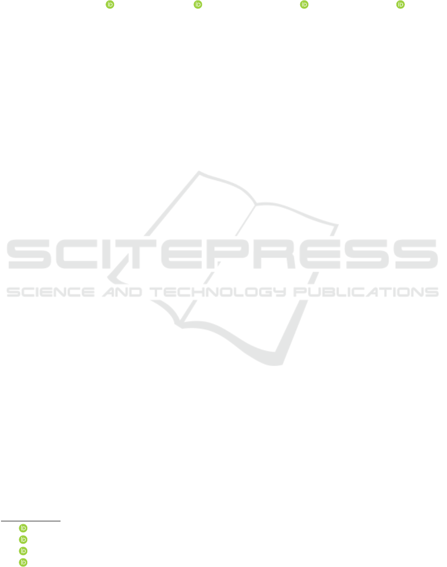
modeling. The concept of an AAS as Digital Twin
implementation is shown in Figure 1.
The paper is structured as follows: Section 2 in-
troduces the reader to the fields of Model-Based Sys-
tem Engineering and Digital Twins, and reviews re-
lated work addressing these topics. Additionally, it
discusses the state of the art in the creation of Dig-
ital Twins using MBSE methods, as well as a com-
parison to approaches similar to the one presented
in this paper. Section 3 describes the various com-
ponents of the AAS Metamodel, including the As-
set Administration Shell (AAS), Submodels, and Sub-
model Elements like Enities and Properties. Section
4 explains our approach to automatically generate a
functional operating Digital Twin in form of a BaSyx
AAS, by evaluating a given MBSE Model. Section
5 shows an example use case of a UML model of a
generic space satellite, which shall be automatically
transformed into a Digital Twin by using our approach
and the prototypical implementation of our Enterprise
Architect (EA) Add-In. It was decided to use UML
instead of SysML to indicate that the presented ap-
proach is applicable to all UML-based modeling lan-
guages. Section 6 provides the technical background
of our prototypical implementation and explains how
we were able to realise the approach described in Sec-
tion 4. Section 7 outlines the key benefits of the ap-
proach, including automation of Digital Twin gener-
ation, high accuracy, scalability, seamless integration
with industry standards, legacy system adaptation, ef-
ficient life-cycle management, and the reuse of exist-
ing MBSE models. Section 8 concludes the main re-
sults of our work and provides an outlook on future
activities.
Figure 1: Concept of the Asset Administration Shell (AAS)
to implement a standardised Digital Twin.
2 RELATED WORK
For a better comprehension of our proposed approach,
the concepts of MBSE and Digital Twin are de-
scribed below and relevant work in both areas is ad-
dressed. Furthermore, we examine the current ad-
vancements in creating and managing Digital Twins
through MBSE methodologies and provide a analy-
sis of approaches that are comparable to the approach
presented in this paper.
2.1 Model-Based System Engineering
Model-Based System Engineering (MBSE), as de-
fined by the International Council on Systems En-
gineering (INCOSE), aims to streamline traditional
document-centric systems engineering practices by
formalizing models to represent requirements, design,
analysis, and validation throughout the entire devel-
opment lifecycle (International Council on Systems
Engineering, 2007)(International Council on Systems
Engineering, 2014). While MBSE promises to en-
hance development by facilitating information reuse
and consolidating data into a single system model,
practical implementation necessitates various views
to address system complexity effectively. Creating a
comprehensive system model involves three core ele-
ments: method, language, and tool (Gr
¨
aßler and Ol-
eff, 2022). The method dictates the necessary steps
MODELSWARD 2025 - 13th International Conference on Model-Based Software and Systems Engineering
76
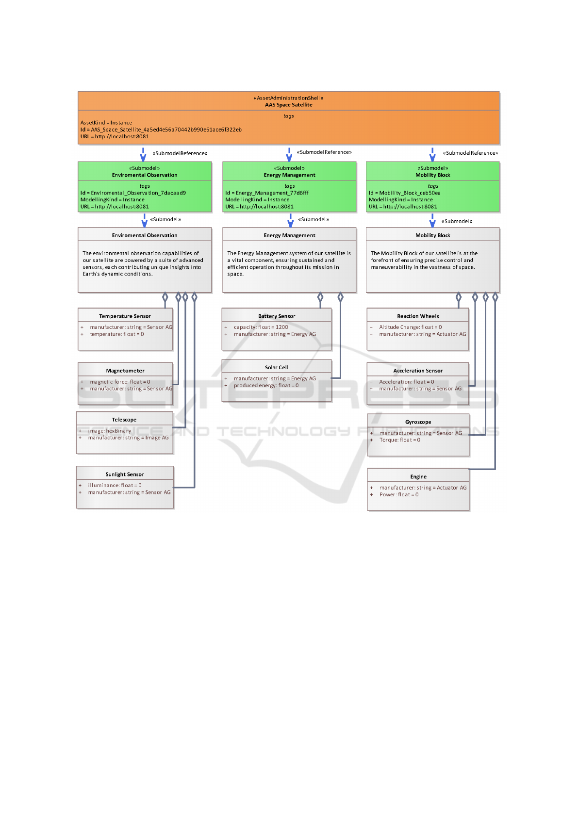
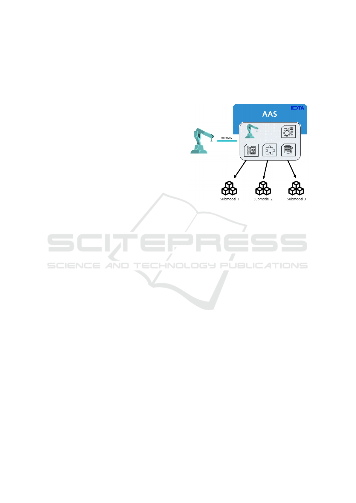
Figure 2: Cut-out from a UML satellite model as an example for the automatic generation of a Digital Twin based on a MBSE
model (Fraunhofer IESE, 2024).
and rules, determining the appropriate level of ab-
straction. The language defines the model’s syntax
and semantics, while the tool provides a graphical
user interface aligned with the chosen language for
model realization.
Overall, while MBSE holds promise for improved
system development, practical implementation re-
quires understanding the relationships between life-
cycle phases and model-driven development steps,
as well as the appropriate tool usage at each stage.
This highlights the ongoing need for further automa-
tion and integration to achieve seamless MBSE adop-
tion (International Council on Systems Engineering,
2014)(International Council on Systems Engineering,
2022). In software development, the conventional
approach often involves translating requirements di-
rectly into code, resulting in challenges with complex
systems, such as quality issues and increased devel-
opment time and costs. To mitigate these challenges,
a step-wise refinement from requirements to architec-
ture, design, and then code is recommended. How-
ever, a more advanced approach, known as Model-
Driven Engineering (MDE), emphasizes modeling
over programming. MDE involves creating artifacts
similar to traditional software engineering but priori-
tizes semi-automated model transformations for sub-
Automated Generation of Standardised Digital Twins Based on MBSE Models
77

sequent steps. This approach demands formally de-
fined syntax and unambiguous semantics to ensure
consistent and development-oriented models.
2.2 Digital Twin
The concept of the Digital Twin was first introduced
by Grieves in 2002 as part of a presentation about
Product Lifecycle Management (Grieves, 2002). Both
Digital Twins and Digital Shadows are digital rep-
resentations of all relevant attributes and properties
of an existing physical or conceptual asset. Bergs
et al. state in their paper ”The Concept of Digital
Twin and Digital Shadow in Manufacturing” (Bergs
et al., 2021) that a Digital Shadow is characterized by
a one-way data flow from an existing physical object
to a digital model. This model reflects the state of the
physical object, and any changes in the physical ob-
ject’s state are mirrored in the digital representation.
However, the flow of data does not occur in reverse.
In contrast, for a Digital Twin, data flows seamlessly
between the physical and digital objects in both direc-
tions, creating a fully integrated relationship between
the two entities. In today’s digital world, it is manda-
tory to have bidirectional communication between the
asset and its representation for it to be a functional
Digital Twin (Grieves and Vickers, 2017). As a re-
sult, a Digital Twin is a Cyber-Physical System, com-
bining the virtual and physical worlds, but with a new
focus on data and simulation (Tao et al., 2019). By
definition, Digital Twins and Cyber-Physical Systems
try to create ways of interaction and interoperability
between companies, their partners, and whole indus-
tries (Bader and Maleshkova, 2019).
Industry 4.0 (I4.0) introduces the foundational
concept of Asset Administration Shell (AAS) to rep-
resent and manage Digital Twins, by offering a struc-
tured, hierarchical, and machine-readable represen-
tation of the diverse aspects of assets and has been
published as European standard IEC 63278-1 (Inter-
national Electrotechnical Commission, 2023). It was
defined by the Plattform Industrie 4.0 as a specifica-
tion for an industry-ready Digital Twin, while the Ref-
erence Architecture Model Industrie 4.0 (RAMI 4.0)
describes it as a digital representation of I4.0 com-
ponents (Bader, 2020). (Tantik and Anderl, 2017)
used the requirements of the AAS to roughly define
its structure by creating a frame of several segments,
which try to solve the problems facing a Digital Twin.
On both sides of the AAS, there are interfaces, one for
external and one for internal communication between
I4.0 systems and the asset itself. For our implemen-
tation we use the MIT licensed Open Source Middle-
ware Eclipse BaSyx (The Eclipse Foundation, 2024b)
(The Eclipse Foundation, 2024a), which is a reference
implementation of the concepts for I4.0 and uses the
AAS to represent a Digital Twin based on the latest
AAS specification (AAS Version 3) provided by the
(Industrial Digital Twin Association (IDTA)), 2023).
2.3 State of the Art
In the following, the current state of the art is dis-
cussed, which deals with the integration of MBSE
methods in the creation process of Digital Twins.
(Heithoff et al., 2023) and (Bordeleau et al., 2020)
examine the challenges in the initial generation of
Digital Twins and how these can be overcome us-
ing MBSE methods. Both (Spaney et al., 2023) and
(Bibow et al., 2020) present architectural models as
concepts for building and using model-based Digi-
tal Twins. In addition to our method, (Bibow et al.,
2020), (Nast et al., 2023) and (Dhouib et al., 2023)
also pursue an approach for the automated genera-
tion of Digital Twins from MBSE models. These
approaches share the same core idea as our contribu-
tion, but differ in their implementation. In (Nast et al.,
2023), a model created in the ADOxx modeling tool
is analyzed to create a web-based Digital Twin using
JSON, but it is specific to this solution and does not
take advantage of the standardised AAS concept. The
same applies to (Bibow et al., 2020), whose approach
evaluates a model created in the MontiArc model-
ing tool and tags its content with a domain-specific,
text-based language to define events inside the Digi-
tal Twin. We consider this approach to be ambitious,
but tend to separate the definition of the data struc-
ture of the Digital Twin from its event planning and
autonomous services. The approach presented in this
paper is most similar to that of (Dhouib et al., 2023),
as it also generates an AAS based on an MBSE model.
As a modeling tool (Dhouib et al., 2023) uses the
tool Papyrus. The main difference to (Dhouib et al.,
2023) is that in our approach, any existing UML-
based model (e.g. SysML) can be directly used to
generate an AAS, whereas (Dhouib et al., 2023) de-
fines its own metamodel specific for the purpose of
AAS creation. This means that the AAS in (Dhouib
et al., 2023) must first be modeled manually from
scratch, or based on an existing MBSE model, before
the Digital Twin can be generated automatically.
3 AAS METAMODEL
The vendor independent standardised Digital Twin
specification Asset Administration Shell (AAS), de-
veloped as part of the Plattform Industrie 4.0 initia-
MODELSWARD 2025 - 13th International Conference on Model-Based Software and Systems Engineering
78
Figure 3: Cut-out from the BaSyxWeb-UI, showing the resulting generated Digital Twin Instance of the example Satellite
System Digital Twin.
tive, and maintained by the (Industrial Digital Twin
Association (IDTA)), 2023), serves as a real time dig-
ital representation of physical assets. The AAS is
built around two primary concepts: the information
related to the asset itself and the Submodels that en-
capsulate its functionalities and manage its data. In
this context, the AAS can represent both types and in-
stances of assets, as prescribed by the Reference Ar-
chitecture Model Industrie 4.0 (RAMI 4.0) (Grangel-
Gonz
´
alez et al., 2016). Each AAS, its Submodels, and
related elements such as concept descriptions are as-
signed unique global identifiers, while properties and
similar elements only require local identifiers within
their respective Submodels. The concept and decom-
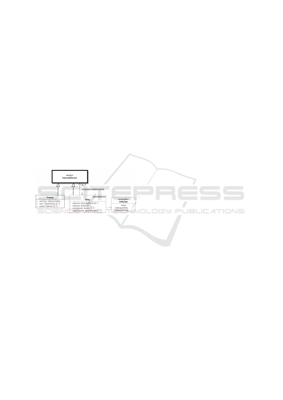
position of a AAS is shown in Figure 1. A part of
the AAS metamodel is shown in Figure 4, with fo-
cus specifically on the elements that are relevant to
our approach. The complete AAS metamodel can
be accessed in (Industrial Digital Twin Association
(IDTA)), 2023).
3.1 Asset Administration Shell
The Asset Administration Shell element represents a
single real world physical or non-physical asset. The
assetKind attribute is used to designate whether an
AAS represents a type (template) or an instance of
that asset. An AAS usually links to multiple Submod-
els describing the contents of an asset regarding a spe-
cific use case. The AAS does not own those Submod-
els, so that a Submodel itself can be existent without
a AAS referencing it. Also, one Submodel can theo-
retically be referenced by multiple AAS.
3.2 Submodel
Submodels are critical to the structure an AAS, as they
organize its digital representation and technical func-
tionality. Each Submodel focuses on a specific do-
main or aspect of the asset, enabling the modularity
and flexibility needed to manage complex systems.
Submodels can be standardised to ensure uniformity
across industries, or they can be customized to fit
unique requirements. Submodels own multiple Sub-
model Elements, that can be data elements of various
types like Entities or Properties. Those Submodel El-
ements are owned by the Submodel and cannot exist
without it.
3.3 Submodel Element
Submodel Elements come in several forms, such as
collections, Entities or Properties. Submodel Ele-
ments describe specific characteristics or functional-
ities of the asset. This versatility allows Submodels
to capture the complex relationships and behaviors of
physical assets within digital environments. The Sub-
model Element description itself is abstract, as shown
in Figure 4.
3.4 Property
Properties are Submodel Elements that store a single
value, such as temperature, pressure, or status. These
values are typed according to the standard W3C XML
Schema (Biron and Malhotra, 2004), which provides
a wide range of predefined and derived data types. All
Automated Generation of Standardised Digital Twins Based on MBSE Models
79
available data types are listed in Figure 5. The precise
definition of property values allows for accurate data
exchange and interpretation across systems, ensuring
that Digital Twins can function effectively in diverse
environments across multiple vendors.
3.5 Entity
The Entity Submodel Element is able to describe the
hierarchical structure of an asset. The system de-
composition of the asset can be reflected by embed-
ding multiple Entities within one another. Entities
are classified as either co-managed or self-managed,
depending on whether they have their own AAS for
detailed representation. Co-managed entities are de-
scribed in more depth through their own AAS, while
self-managed entities rely on the parent AAS for rep-
resentation. Entities contain so called Statements,
which are composed of any type of Submodel Ele-
ments. Those can be Properties to describe values of
that Entity or other Entities to build up a more com-
plex system decomposition.
Figure 4: Highly simplified Metamodel of the AAS specifi-
cation (Industrial Digital Twin Association (IDTA)), 2023),
reduced to highlight the contents used by the approach pre-
sented in this paper.
4 APPROACH
The approach presented in this paper enables the au-
tomated generation of Digital Twins using an MBSE
model of the physical system to be represented. To
achieve this, the original model must be slightly ex-
tended with additional model elements. These ele-
ments serve as anchor points for the subsequent gen-
eration of Asset Administration Shells (AAS) and
Submodels. These additional elements contain meta
information, such as the URL where the AAS and
Submodel repositories are made available, as well as
other metadata describing the AAS and Submodels
according to the AAS specification (Industrial Digital
Twin Association (IDTA)), 2023). To further specify
the transformation from a MBSE model to a Digital
Twin, additional connectors with the special stereo-
type Submodel and SubmodelReference must be cre-
ated. Submodel connectors are used to define the en-
try points for the automated generation of AAS Sub-
models, while SubmodelReference connectors define
which Submodel can be accessed within a particular
AAS. This relation-based approach ensures a targeted
and controlled extraction of relevant parts from the
entirety of the model. When the AAS generation pro-
cess is started, an automated evaluation of the sys-
tem model is triggered. This evaluation includes an
analysis of the given model decomposition, the con-
tained model elements and the relevant element at-
tributes. Predefined attribute types and initial values
are also included in the generation of Submodels and
their Properties. Once all the necessary AAS and Sub-
model elements have been added to the model and
linked to the corresponding parts of the model, the
final step is the automated generation of a ready-to-
use and operational Digital Twin. The generated Dig-
ital Twin is now ready to be connected to real sen-
sors, actuators and hardware modules of the appro-
priate physical system. This MBSE-driven definition
and automated generation of Digital Twins, not only
speeds up the initial creation process, but also ensures
consistency between the resulting Digital Twin and its
real-world counterpart. In this way the system model
can be automatically transformed in a AAS Type (tem-
plate) for future refinement or a individual AAS In-
stance, which represents one unique system in the real
world. By applying the generation algorithm, a single
MBSE model can be used to realize multiple parallel
instances of Digital Twins (DTI). By re-running the
algorithm, a completely new Digital Twin Instance
(DTI) can be created, or an already created DTI can
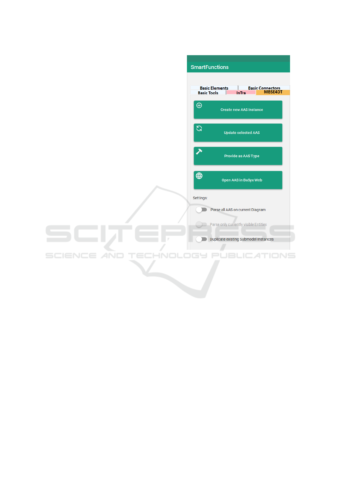
be updated to the current model state. These appli-
cation possibilities also reflect in the UI of the En-
terprise Architect Add-In prototype, shown in Figure
7. In addition, behavioral specifications such as state
machines and activity and sequence diagrams can be
integrated into the MBSE model to capture the data
transfer to other systems. The documentation of the
Digital Twin using established MBSE methods offers
numerous additional advantages in the maintenance,
management and care of a Digital Twin throughout
its entire life cycle.
5 EXAMPLE USE CASE: SPACE
SATELLITE
As a demonstration of the functionality of this ap-
proach, we have created a UML model of a simpli-
fied generic space satellite, which is shown in Figure
2. Although it is a system model, it was decided to
MODELSWARD 2025 - 13th International Conference on Model-Based Software and Systems Engineering
80
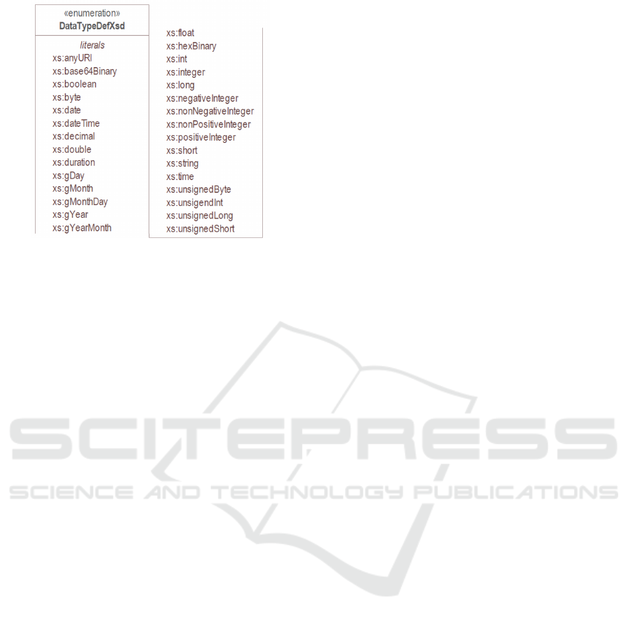
Figure 5: TypeDefXsd Datatypes as specified in (Industrial
Digital Twin Association (IDTA)), 2023).
use UML instead of SysML to indicate that the pre-
sented approach is applicable to all UML-based mod-
eling languages. Nevertheless, the approach would
work in the same way if applied to a SysML model
instead, highlighting its versatility across UML-based
modeling languages. The satellite consists of various
components, which are divided into three functional
blocks: Environmental Monitoring, Energy Manage-
ment and Mobility. A temperature sensor, a sunlight
sensor, a magnetometer and a telescope are used for
environmental monitoring. The energy management
consists of a solar cell with a battery and a battery
sensor. The movement of the satellite is realized by
a group of reaction wheels, a gyroscope, a motor and
an acceleration sensor. In the model shown, all sen-
sors have at least one attribute that later represents the
current measured value in the Digital Twin, and all
actuators have an attribute that represents the current
control value. These attributes can be further refined
in the attribute view shown in Figure 6. The model
also specifies the unit of measurement of the values
and the data type used to store the values in digitized
form (Int, Float, String, etc.). This information will
also be transferred to the generated Digital Twin, with
the AAS standard ensuring data typing in compliance
with the W3C XML Schema (Biron and Malhotra,
2004), as shown in Figure 5.
Each of these attributes is also provided with an
initial value. This initial value serves as a temporary
placeholder in the AAS until the real physical system
has been connected to the Digital Twin and the first
real value is available. In addition, all elements have
a Manufacturer attribute, which contains the name of
the manufacturer of the sensor or actuator. The sys-
tem shown here is of course a very simplified example
model, which is far from representing a real satellite
and would in practice have many additional individ-
ual attributes for each individual sensor. Nevertheless,
this simplified model demonstrates the functionality
of our approach and helps with its comprehensibility.
The complete satellite model is also available online
for download (Fraunhofer IESE, 2024) and can be ac-
cessed as an Enterprise Architect file, Model-XML
file or as a PDF file. In order to be able to auto-
matically generate a Digital Twin from the example
model shown in Figure 2, we need to create an ad-
ditional element in the model with the stereotype As-
setAdministrationShell, which represents a new AAS
to access relevant Submodels of the satellite. In our
example from Figure 2, this is the element with the
name AAS Space Satellite. In addition, we need to
provide meta information for this element such as an
AssetKind and the URL for the correct addressing of
the AAS repository. At this point, it should be men-
tioned that the Id attribute, which is used to uniquely
address the AAS, does not need to be specified man-
ually, as this attribute is automatically generated from
the name of the AAS and a unique UUID when the
algorithm is executed. The Id is always generated au-
tomatically and saved in the model if it does not yet
exist at the time the Digital Twin is generated.
In the next step, we must define which parts of the
MBSE model are to be generated as Submodels by
linking these parts of the model with special model el-
ements of the Submodel stereotype. These Submodel
elements are also shown in Figure 2. To achieve this
assignment, we use connectors of the stereotype Sub-
model, which point to the corresponding elements in
the model. In addition, we create SubmodelRefer-
ence connectors, which assign a Submodel to an As-
set Administration Shell model element. In our ex-
ample, we create a separate Submodel for each func-
tion block (Environmental Monitoring, Energy Man-
agement and Mobility) of the satellite and link these
to a single AAS for the entire satellite system. Meta-
data such as URL and ModelingKind must also be de-
fined for these Submodel elements. The Id attribute
is (again) generated randomly if it does not already
exist.
As soon as the preparation of the model has been
completed by creating these few additional elements,
the generation process can be initiated. All elements
that are addressed by Submodel elements through
Submodel connectors are analyzed and their decom-
position is further evaluated. Each element in the
model that has an aggregation or composition con-
nector with one of these elements is constructed as
part of an Entity in the resulting AAS. As mentioned
in Section 3.5, each Entity can contain a list of En-
tities or Properties in its Statement attribute. In this
way, any number of decomposition levels can be real-
Automated Generation of Standardised Digital Twins Based on MBSE Models
81
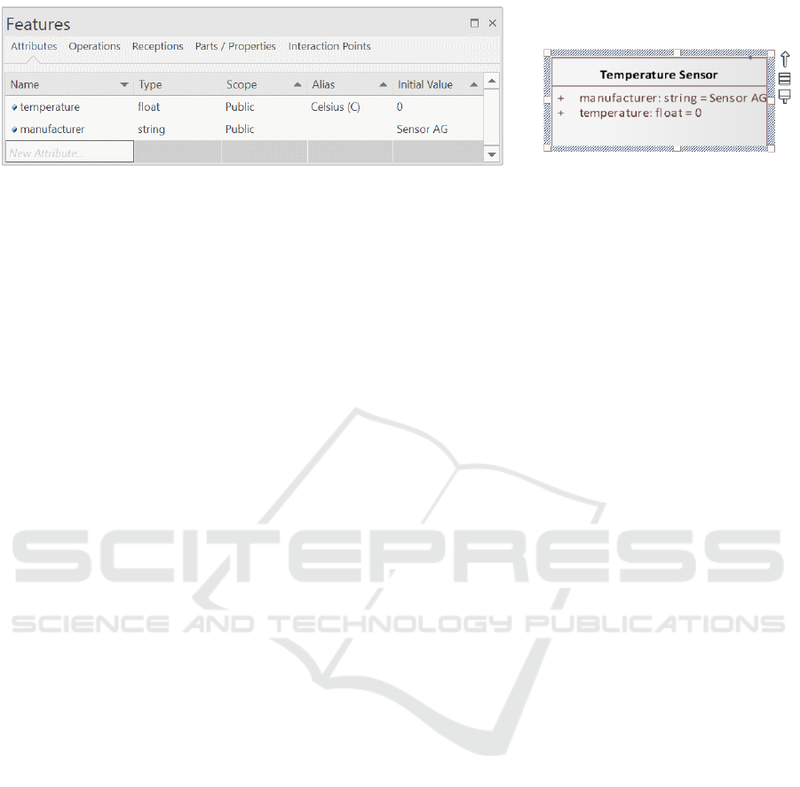
Figure 6: Attribute view of the Temperature Sensor Interface element (Fraunhofer IESE, 2024).
ized in the resulting Digital Twin, based on the given
model decomposition. For a more detailed consider-
ation of the elements and attributes described above,
the complete Enterprise Architect model of the satel-
lite scenario described can be downloaded from the
following reference (Fraunhofer IESE, 2024).
In order to perform the automated generation of
the AAS, our application requires a running instance
of the BaSyx middleware (The Eclipse Foundation,
2024b) (The Eclipse Foundation, 2024a), which im-
plements the current IDTA specification (Industrial
Digital Twin Association (IDTA)), 2023) of Asset
Administration Shells. Once the generation process
has been executed, the resulting Digital Twin is cre-
ated in a few seconds, uploaded into the BaSyx envi-
ronment and displayed in the BaSyx WebUI as shown
in Figure 3. On the left side of Figure 3 we see the
resulting AAS and its Id, which is used to explic-
itly address this AAS using the BaSyx REST API.
The middle column of Figure 3 contains all Sub-
models that are referenced via the selected AAS in
the left-hand column. It can be seen that all three
functional blocks (Environmental Monitoring, En-
ergy Management and Mobility) of the system model
were created as Submodels in the resulting Digital
Twin. Each Submodel contains corresponding Enti-
ties for sensors and actuators. Properties are also in-
cluded, which contain the Asset Administration Shell
attributes Name, Description, ValueType and Value.
In Figure 3, the Temperature property is selected in
the currently selected Submodel, which is therefore
shown in detail in the right-hand column. In the de-
tails shown there, we can see that the Temperature
value is measured in Celsius (C), the ValueType has
been defined as xs:float and the current temperature
value is 0 (initial value). Additionally, at the bottom
of the right column, we can see when this value was
last synchronized by the BaSyx server. These prop-
erties are now ready to process real values from the
real-world system.
6 PROTOTYPICAL
IMPLEMENTATION
In order to make our approach applicable, we have
realised a prototype implementation that follows the
procedure from Section 5. We prepared our example
model inside the modelling tool Enterprise Architect
by Sparx Systems and developed an Add-In written in
the programming language C#, to evaluate a MBSE
model and automatically generate a Digital Twin in
the form of an AAS (Version 3.0) (Industrial Digital
Twin Association (IDTA)), 2023). The technical real-
isation of the Digital Twin was archived by using the
MIT-licensed open source middleware Eclipse BaSyx
(The Eclipse Foundation, 2024b) (The Eclipse Foun-
dation, 2024a). In addition, a C# .NET Framework
translation of the AAS class library AAS4J (Asset
Administration Shell for Java) (The Eclipse Founda-
tion, 2024) was used. By using this library translation
and the BaSyx REST API, we were able to directly
integrate the BaSyx client functionality inside the C#
Code of the EA Add-In. This way the model data is
directly read from the EA-API, analysed in our C# ap-
plication, and then written to the Digital Twin using
the BaSyx REST API. This implementation allows
a straightforward transmission of the MBSE model
from EA into a BaSyx based Digital Twin realisation.
By activating the generation algorithm through the
provided EA Add-In UI shown in Figure 7, the cre-
ation of the Digital Twin is started and after a few sec-
onds the ready to use AAS is generated and uploaded
to the prepared BaSyx server addressed in the URL
attribute, as mentioned in Section 4 and 5. The gen-
erated Digital Twin will either be uploaded as a AAS
Type (template) for future refinement or as an Digital
Twin Instance (DTI) representing a unique real-world
system. The various application options are also vis-
ible in the UI of the EA-Add-In, shown in Figure 7.
The most important part of the algorithm is of course
the method for analyzing the model content and au-
tomatically mapping this content to the standardised
AAS structure (Industrial Digital Twin Association
(IDTA)), 2023).
MODELSWARD 2025 - 13th International Conference on Model-Based Software and Systems Engineering
82
7 KEY BENEFITS
The key benefits of this approach center around au-
tomating the generation of Digital Twins from MBSE
models. By automating the creation of Digital Twins,
the approach significantly reduces manual effort and
accelerates the implementation process. This effi-
ciency is particularly advantageous when handling
complex systems, where traditional methods would
be time-consuming and labor-intensive.
Another notable advantage is the high accuracy
and fidelity of the generated Digital Twins. Because
they are derived from detailed MBSE models, the
Digital Twins retain a high level of precision, faith-
fully reflecting the system’s specifications. This leads
to more reliable and realistic representations of phys-
ical assets in their digital form.
The approach also promotes scalability and maintain-
ability. The use of MBSE principles ensures that the
Digital Twins are built on a structured foundation,
making it easier to scale them as the system grows
or evolves. This also facilitates updates and modi-
fications throughout the system’s lifecycle, ensuring
that the Digital Twin remains a dynamic, up-to-date
reflection of the asset.
Another key benefit is the seamless integration
with industry standards. The Digital Twins generated
from this approach adhere to the standardised struc-
ture of the Asset Administration Shell (AAS) (Indus-
trial Digital Twin Association (IDTA)), 2023), ensur-
ing compatibility with various systems and compli-
ance standards. This standardization simplifies inter-
operability, making it easier to integrate the Digital
Twins into broader industrial ecosystems.
Lastly, the reuse of existing MBSE model for gen-
erating Digital Twins consolidates information, re-
ducing redundancies and improving data consistency
across different lifecycle stages. This use of data not
only saves time but also ensures a higher level of con-
sistency in system representation, further enhancing
the reliability and efficiency of the resulting Digital
Twins.
8 CONCLUSION AND FUTURE
WORK
This publication contributes to the automation of the
generation of Digital Twins based on MBSE mod-
els. The aim is to facilitate both the initial creation,
the documentation and the maintenance of the result-
ing Digital Twin throughout its lifecycle. To make
our approach applicable, we have realized a prototype
implementation in the Enterprise Architect modeling
Figure 7: User Interface of the developed Enterprise Archi-
tect Add-in, to apply the approach presented in this paper to
a chosen MBSE model.
tool from Sparx Systems, which follows the approach
from Section 4.
In the future, we plan to expand the approach with
additional functions to make it even more attractive
for productive use. In particular, the analysis and au-
tomated mapping between the elements of the MBSE
model and the elements of the Asset Administration
Shell must be a focus of further research in this area.
The link between AAS Entities of the self-managed
Entity type as mentioned in Section 3, and their as-
sociated reference AAS should also be definable via
the MBSE model in future implementations of the ap-
proach. In addition, we are also considering support-
ing other modeling tools as Enterprise Architect in the
future by outsourcing the analysis algorithm. Addi-
tionally, it would be highly advantageous to support
the conceptualization of new Digital Twins as part of
research projects, allowing for the acquisition of fur-
ther practical experience with the approach.
Automated Generation of Standardised Digital Twins Based on MBSE Models
83

REFERENCES
Albuquerque, G., Fischer, P. M., Azeem, S. M., Bernstein,
A.-C., Utzig, S., and Gerndt, A. (2023). Digital Twins
as Foundation for Augmented Reality Applications in
Aerospace, pages 881–900. Springer International
Publishing, Cham.
Bader, S. (2020). Details of the Asset Administration Shell.
Part 1 - The exchange of information between partners
in the value chain of Industrie 4.0 (Version 3.0RC01).
Federal Ministry for Economic Affairs and Energy
(BMWi).
Bader, S. R. and Maleshkova, M. (2019). The seman-
tic asset administration shell. In Acosta, M., Cudr
´
e-
Mauroux, P., Maleshkova, M., Pellegrini, T., Sack,
H., and Sure-Vetter, Y., editors, Semantic Systems. The
Power of AI and Knowledge Graphs, pages 159–174.
Springer International Publishing.
Bergs, T., Gierlings, S., Auerbach, T., Klink, A.,
Schraknepper, D., and Augspurger, T. (2021). The
concept of digital twin and digital shadow in manu-
facturing. Procedia CIRP, 101:81–84. 9th CIRP Con-
ference on High Performance Cutting.
Bibow, P., Dalibor, M., Hopmann, C., Mainz, B., Rumpe,
B., Schmalzing, D., Schmitz, M., and Wortmann, A.
(2020). Model-driven development of a digital twin
for injection molding. In Dustdar, S., Yu, E., Sali-
nesi, C., Rieu, D., and Pant, V., editors, Advanced In-
formation Systems Engineering, pages 85–100, Cham.
Springer International Publishing.
Biron, P. V. and Malhotra, A. (2004). Xml schema part
2: Datatypes second edition. W3C Recommenda-
tion. https://www.w3.org/TR/2004/REC-xmlschema-
2-20041028/.
Bordeleau, F., Combemale, B., Eramo, R., van den Brand,
M., and Wimmer, M. (2020). Towards model-driven
digital twin engineering: Current opportunities and
future challenges. In Babur,
¨
O., Denil, J., and Vogel-
Heuser, B., editors, Systems Modelling and Manage-
ment, pages 43–54, Cham. Springer International Pub-
lishing.
Dhouib, S., Huang, Y., Smaoui, A., Bhanja, T., and Gezer,
V. (2023). Papyrus4manufacturing: A model-based
systems engineering approach to aas digital twins.
pages 1–8.
Fraunhofer IESE (2024). Example space satel-
lite - enterprise architect model download.
https://oc.iese.de/index.php/s/
BEXAJEwn5wBFSNJhnw909rM5PVqe9SuZ.
Grangel-Gonz
´
alez, I., Halilaj, L., Coskun, G., Auer, S., Col-
larana, D., and Hoffmeister, M. (2016). Towards a
semantic administrative shell for industry 4.0 compo-
nents. In 2016 IEEE Tenth International Conference
on Semantic Computing (ICSC), pages 230–237.
Grieves, M. (2002). Conceptual ideal for plm. Presentation
for the Product Lifecycle Management (PLM) center,
University of Michigan.
Grieves, M. and Vickers, J. (2017). Digital twin: Mitigat-
ing unpredictable, undesirable emergent behavior in
complex systems. In Transdisciplinary perspectives
on complex systems, pages 85–113. Springer.
Gr
¨
aßler, I. and Oleff, C. (2022). Systems engineering: ver-
stehen und industriell umsetzen. Springer Vieweg,
Berlin [Heidelberg].
Heithoff, M., Konersmann, M., Michael, J., Rumpe, B.,
and Steinfurth, F. (2023). Challenges of integrating
model-based digital twins for vehicle diagnosis.
Industrial Digital Twin Association (IDTA)) (2023).
Specification of the Asset Administration
Shell. Industrial Digital Twin Associa-
tion. https://industrialdigitaltwin.org/content-
hub/aasspecifications.
International Council on Systems Engineering (2007). Sys-
tems Engineering Vision 2020: Integrating frame-
work.
International Council on Systems Engineering (2014). Sys-
tems Engineering Vision 2025: A world in mo-
tion. Technical report. https://www.incose.org/about-
systems-engineering/se-vision-2025.
International Council on Systems Engineering (2022).
Systems Engineering Vision 2035: Engineer-
ing solutions for a better world. Technical
report. https://www.incose.org/about-systems-
engineering/se-vision-2035.
International Electrotechnical Commission
(2023). International standard iec 63278-1.
https://webstore.iec.ch/publication/65628.
Nast, B., Reiz, A., Ivanovic, N., and Sandkuhl, K. (2023). A
modeling approach supporting digital twin engineer-
ing: Optimizing the energy consumption of air condi-
tioning facilities.
Spaney, P., Becker, S., Str
¨
obel, R., Fleischer, J., Zenhari, S.,
M
¨
ohring, H.-C., Splettst
¨
oßer, A.-K., and Wortmann,
A. (2023). A model-driven digital twin for manu-
facturing process adaptation. In 2023 ACM/IEEE In-
ternational Conference on Model Driven Engineer-
ing Languages and Systems Companion (MODELS-
C), pages 465–469.
Tantik, E. and Anderl, R. (2017). Integrated data model and
structure for the asset administration shell in indus-
trie 4.0. Procedia CIRP, 60:86–91. Complex Sys-
tems Engineering and Development Proceedings of
the 27th CIRP Design Conference Cranfield Univer-
sity, UK 10th – 12th May 2017.
Tao, F., Zhang, H., Liu, A., and Nee, A. Y. C. (2019). Dig-
ital twin in industry: State-of-the-art. IEEE Transac-
tions on Industrial Informatics, 15(4):2405–2415.
The Eclipse Foundation (2024). Aas4j - opensource github
repository. https://github.com/eclipse-aas4j/aas4j.
The Eclipse Foundation (2024a). Eclipse basyx - open-
source github repository. https://github.com/eclipse-
basyx.
The Eclipse Foundation (2024b). Eclipse basyx - website.
https://eclipse.dev/basyx/about/.
MODELSWARD 2025 - 13th International Conference on Model-Based Software and Systems Engineering
84
