
Development of a New Architecture for next Generation e-Bikes
Tiago Gândara
1a
and José Santos
2b
1
Departamento de Engenharia Mecânica, Campus Universitário de Santiago, 3810-193 Aveiro, Portugal
2
TEMA-Centro de Tecnologia Mecânica e Automação, Departamento de Engenharia Mecânica,
Universidade de Aveiro, Campus Universitário de Santiago, 3810-193 Aveiro, Portugal
Keywords: e-Bike, System Architecture, Battey Management System, Motor Controller.
Abstract: The growing e-bike market demands more efficient, connected, and user-friendly systems. However, existing
e-bike architectures are closed, limiting the integration of new technologies such as power management
algorithms and security features. This paper proposes a new system architecture utilizing a microcontroller-
based motor controller and CAN bus, allowing integration and data exchange with external devices.
Experimental testing was conducted to validate the system’s functionality, including testing energy efficiency
improvements and security features such as emergency stop protocols. Results demonstrate that the proposed
architecture can enhance energy efficiency and provides reliable security, offering a flexible and scalable
solution for future e-bike developments.
1 INTRODUCTION
With the increasing popularity of electric bicycles (e-
bikes) as a sustainable mode of transportation, the
demand for systems tailored to their specific needs
has risen. E-bikes offer numerous benefits, including
reduced reliance on fossil fuels, decreased urban
congestion, and improved accessibility to
transportation (Fishman and Cherry, 2016). These
advantages have contributed to the rapid growth of
the e-bike market. In Europe alone, the market is
projected to expand from $19.36 billion in 2024 to
$29.28 billion by 2029, with a compound annual
growth rate (CAGR) of 8.63% (Mordor Intelligence,
2024).
Besides individual ownership, bike-sharing
systems have further driven the adoption of e-bikes
by offering sustainable and convenient solutions for
short-term transportation. Beyond their role in
reducing pollution, their minimal space requirements
make them an ideal choice for improving quality of
life in urban environments (Boglietti et al., 2021).
Additionally, studies indicate that 18% to 32% of
bike-sharing users would prefer e-bikes if available
(Schnieder, 2023).
a
https://orcid.org/0009-0004-2040-7155
b
https://orcid.org/0000-0003-0417-8167
As e-bikes become integral to urban mobility,
their underlying technologies must evolve to address
growing user expectations. Recent advancements in
e-bike systems have focused on improving user
experience, safety, and efficiency. Smart
technologies now enable optimized routing to reduce
travel times, enhance security with collision sensors,
and improve energy efficiency to extend range.
Some authors have focused on developing
solutions for bicycle route optimization and data
collection. (Nunes et al., 2020) developed an IoT-
based module embedded in bicycles to collect real-
time sensor data, aiming to enhance cyclists' safety
and provide a web-based connectivity platform for
route optimization and policy support. (Grama et al.,
2018) proposed a modular solution designed to be
adapted based on cyclists' needs. The modules
focused on two primary functions: measuring bicycle
parameters and monitoring environmental conditions.
The goal was to develop a platform for collecting and
sharing data on air pollution in urban environments.
(Andres et al., 2019) used co-operative interaction
between the vehicle and the user to get green traffic
lights by adjusting the vehicle’s speed. (Cammin et
al., 2023) introduced a real-time IoT architecture
designed to address road traffic challenges by
34
Gândara, T. and Santos, J.
Development of a New Architecture for next Generation e-Bikes.
DOI: 10.5220/0013208800003941
Paper published under CC license (CC BY-NC-ND 4.0)
In Proceedings of the 11th International Conference on Vehicle Technology and Intelligent Transport Systems (VEHITS 2025), pages 34-44
ISBN: 978-989-758-745-0; ISSN: 2184-495X
Proceedings Copyright © 2025 by SCITEPRESS – Science and Technology Publications, Lda.

reducing accidents and improving traffic flow
through 5G-enabled smart city integration.
Other authors have developed solutions related to
increasing the autonomy through optimization of
energy consumption. (Arango et al., 2021) developed
experimental models for the efficiency of mid-drive
motor e-bike components and integrated them into a
system-wide efficiency map, maximizing range
without compromising speed. (De La Iglesia et al.,
2017) developed an intelligent motor management
system designed to optimize assistance levels and
reduce battery power consumption. The system
utilized data from bicycle sensors, historical cyclist
data, and neural networks to make informed
decisions, resulting in a 10.32% reduction in
electricity consumption. (Vishnu et al., 2024)
developed a novel control algorithm for a Hybrid
Energy Storage System (HESS) that integrates a
battery and a supercapacitor and proved that the
HESS approach could improve range and
performance.
Some authors have also studied collision
detection in e-bikes, with advancements in sensor
technologies aimed at improving safety and
autonomy in complex environments. For instance,
(Xie et al., 2021) focused on tracking vehicles at
intersections using a narrow, low-density LiDAR
system. (Zhao et al., 2017) developed an autonomous
bicycle equipped with a high-density three-
dimensional LiDAR system, enabling the bicycle to
effectively detect and avoid obstacles, showcasing the
potential of advanced sensor technologies.
Despite these technological advancements,
implementing new systems in e-bikes is challenging
due to the prevalence of closed-system architectures.
Most e-bikes operate as isolated black boxes,
preventing data exchange and integration with
external devices. As a result, integrating advanced
features often requires additional sensors and
microcontrollers, leading to increased system
complexity and costs.
As of today, a system architecture that allows for
data-sharing, embedded algorithms implementation
and easy integration with other modules is yet to be
designed. The proposed architecture aims to bridge
this gap, providing a flexible foundation for the
development and integration of advanced features
that enhance performance, safety, and user
experience.
1.1 Typical e-Bike Architecture
A typical e-bike architecture consists of several key
components including the electric motor, battery,
controller, sensors, human interface, and a battery
management system (BMS). The motor, either hub or
mid-drive, converts electrical energy into mechanical
power, while the battery provides the necessary
energy. The controller manages power flow,
interpreting input from sensors like pedal-assist and
speed sensors to regulate motor output. The human
interface, often a display and control buttons, allows
riders to adjust power modes and monitor key metrics
like speed and battery status. A typical e-bike is
shown in Figure 1.
The battery is responsible for powering the whole
system. Usually, the battery is composed of lithium-
ion cells, which have a nominal voltage of 3.6 volts
(V) and are connected in series of 10, 13 or 14, which
translate into overall nominal battery voltages of 36V,
46.8V or 50.4V, respectively.
Figure 1: Typical e-bike (Lightmobie, 2025).
To improve the e-bikes range and reduce the
electrical current through each lithium cell, typical
batteries use parallel connections of cells. By
connecting multiple cells in parallel (often in
configurations like 3p or 4p), the overall capacity of
the battery is increased, allowing for longer ride times
and reducing strain on individual cells. The battery
management system (BMS) ensures battery safety by
preventing overcharging and overheating. The BMS
is also responsible for collecting voltage data from all
the battery’s cells through individual probes. Despite
the availability of this data, it is often underutilized,
as most motor controllers only acquire limited
information, such as overall voltage for state-of-
charge (SoC) estimation.
Brushless DC (BLDC) motors are widely used in
e-bikes due to their high efficiency, compact size, and
Development of a New Architecture for next Generation e-Bikes
35
low maintenance. Unlike traditional brushed motors,
BLDC motors have no physical brushes, which
reduces friction and wear, resulting in a longer
lifespan and better performance. The controller is
responsible for the motor rotation, which is achieved
by switching power to the motor windings in a precise
sequence based on rotor position feedback from Hall
sensors or sensor-less methods (Xia, C., 2012).
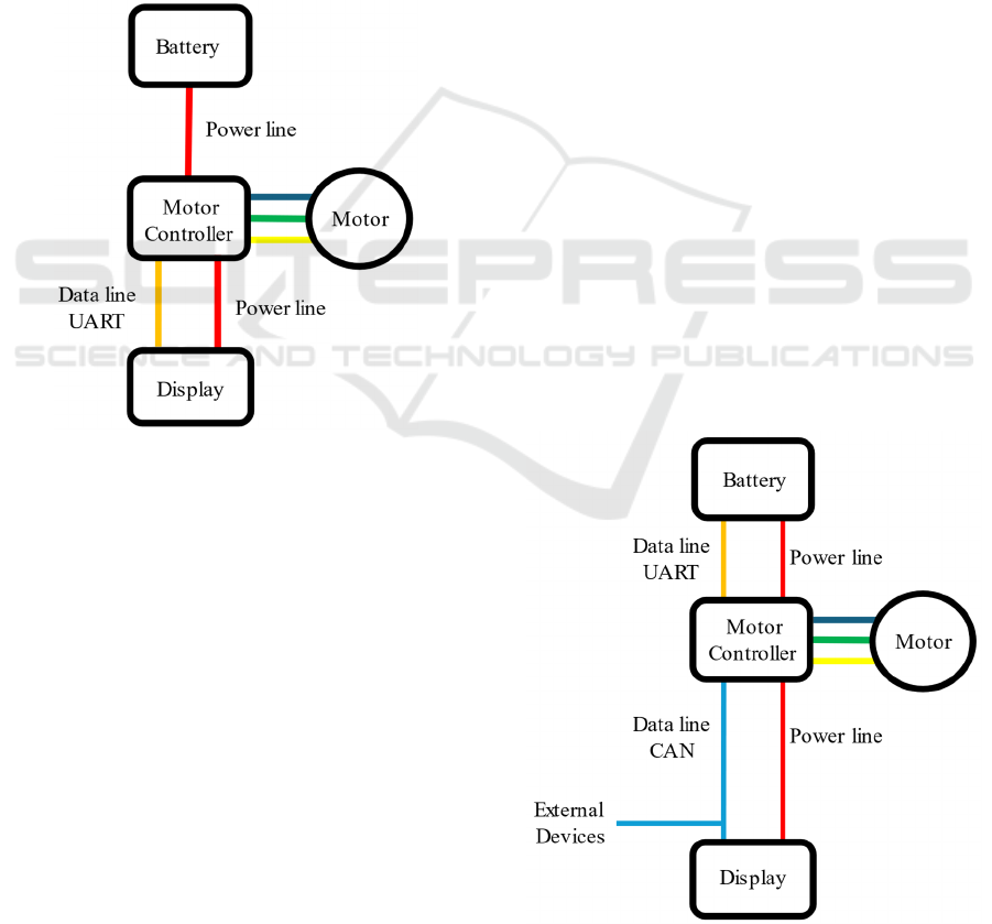
The display is powered by a power line from the
controller, usually of 5V. There is also a data line
which is used by the controller and the display. This
communication is used to exchange information
regarding the speed, SoC and level of assistance, and
the Universal Asynchronous Receiver Transmitter
(UART) protocol is utilized. Figure 2 illustrates a
usual e-bike hardware architecture.
Figure 2: Usual e-bike hardware architecture.
In many current e-bike systems, software-defined
assistance levels and speed limits (e.g., 25 km/h per
the European Standard EN 15194:2017+A1:2023)
dictate performance. However, these systems leave
little room for innovation or adaptability to emerging
technologies. Therefore, in this paper, a new
architecture for any kind of e-bike is proposed.
2 PROPOSED ARCHITECHTURE
The proposed architecture is intended to integrate the
same type of batteries and motors, differing from the
typical architecture only in the controller and display.
To facilitate the integration of future devices and
technologies, all the information handled by the
controller and display must be available to access.
Communication systems for e-bikes can be based on
several protocols, each offering different features and
capabilities. While some options like FlexRay and
automotive Ethernet provide specific benefits for
intra-vehicles networks (Tuohy et al., 2015), CAN
stands out as the ideal choice for e-bike applications.
FlexRay, though fast and fault-tolerant, is too
expensive and complex for e-bikes. Automotive
Ethernet offers high bandwidth but comes with higher
hardware costs. CAN, however, provides a balanced
solution with robust performance, real-time
communication, scalability, and cost-effectiveness,
making it well-suited for integrating subsystems such
as motors, batteries, and controllers in e-bikes (Tuohy
et al., 2015).
Controller Area Network (CAN) is a robust,
message-based communication protocol used for
reliable data exchange between multiple devices in
real-time, commonly in automotive and industrial
systems. It operates on a two-wire bus, where each
device (node) can send and receive messages based
on priority, ensuring efficient communication. CAN
is designed with built-in error detection and fault
tolerance, making it highly reliable in noisy
environments (Navet and Simonot-Lion, 2008).
As of today, most e-bike battery management
systems are only capable of sharing their data through
a simple UART communication protocol. Therefore,
a secondary device may be needed to receive the data
and make it available for other devices in the CAN
network (in this case, the controller). For this reason,
the proposed architecture utilizes a CAN data bus
connecting only the controller and the display, as
displayed in Figure 3.
Figure 3: Proposed architecture.
VEHITS 2025 - 11th International Conference on Vehicle Technology and Intelligent Transport Systems
36
2.1 Controller Architecture
To comply with the requirements of the new
architecture, the new controller must be able to
establish a UART communication with the BMS,
allow for the implementation of energy management
algorithms, share and receive data through the CAN
network, and offer all the functionalities that regular
controllers do. For these reasons, an ESP32
microcontroller was chosen to be the core of the
system.
The ESP32 is a low-cost, low-power
microcontroller with integrated Wi-Fi and Bluetooth,
developed by Espressif Systems. It features a dual-
core processor, multiple GPIO pins, and various
interfaces (such as SPI, I2C, and UART) that support
versatile connectivity and control. It has been shown
that ESP32 is an excellent option for embedded
systems and smart devices due to the performance
properties and price (Maier A. et al., 2017).
2.1.1 Controller Hardware
In this section, the hardware utilized on the controller
and its integration is described. As the battery
supplies a voltage of at least 36V, and the
microcontroller works on either 3.3 or 5V, a voltage
regulator is needed to ensure that the proper voltage
is supplied to the microcontroller. This voltage
regulator is also required to supply any other low-
voltage devices on the controller.
As mentioned before, BLDC motor rotation is
achieved by switching power to the motor windings
in a precise sequence. This switching is usually done
with 6 MOSFETs configured in a three-phase bridge
arrangement, where each phase of the motor has a
pair of MOSFETs (one high-side and one low-side)
controlling the current flow. The MOSFETs are
switched in synchronization with the rotor position,
typically determined by Hall effect sensors, to
maintain optimal magnetic alignment and produce
continuous rotational force. A microcontroller can
detect the motor position in switch power to motor
windings correctly, however this method is usually
avoided because the microcontroller might not be
able to detect the motor’s position fast enough when
its rotation is high.
An alternative solution is to use a dedicated
BLDC motor driver. This device utilizes an analogic
integrated circuit to detect the motor’s position and
switch power accordingly. The motors rotation speed
can be controlled by supplying a signal to the driver,
typically a Pulse Width Modulation (PWM) signal.
Drivers are designed to read the voltage that the PWM
signal generates, and its value must be between 0 and
5 volts. The ESP32’s maximum voltage is 3.3V and,
therefore, voltage level shifters or optocouplers are
required to convert the signals. However, this is not
the case if a 5V microcontroller is utilized.
Since the ESP32’s CAN controller hands only the
digital communication logic, and not the physical
transmission, a CAN transceiver is required to
convert the logic signals into the differential signals
required for the CAN communication. The rest of the
e-bike’s sensors such as pedal and brake sensors can
be connected directly to the microcontroller. Figure 4
is an illustration of all the components that integrate
the controller and how they are connected.
Figure 4: Controller architecture and components.
2.1.2 Controller Software
In order to take full advantage of the ESP32’s
functionalities, the computational workload was split
to run on both CPU cores. Tasks related to speed
reading and calculation, pedal and brake sensor
reading, and motor driver control run on core 0. Tasks
related to communications such as BMS data reading,
CAN data reading and CAN data sending run on core
1. This parallelism reduces latency and improves
general responsiveness of the system, while
simplifying the code structure by assigning specific
tasks to each core. Both cores share a common
memory, allowing each individual task to access data
that was registered by any other task. Figure 5
illustrates the individual tasks, their specific core, and
how they’re sequenced.
Development of a New Architecture for next Generation e-Bikes
37
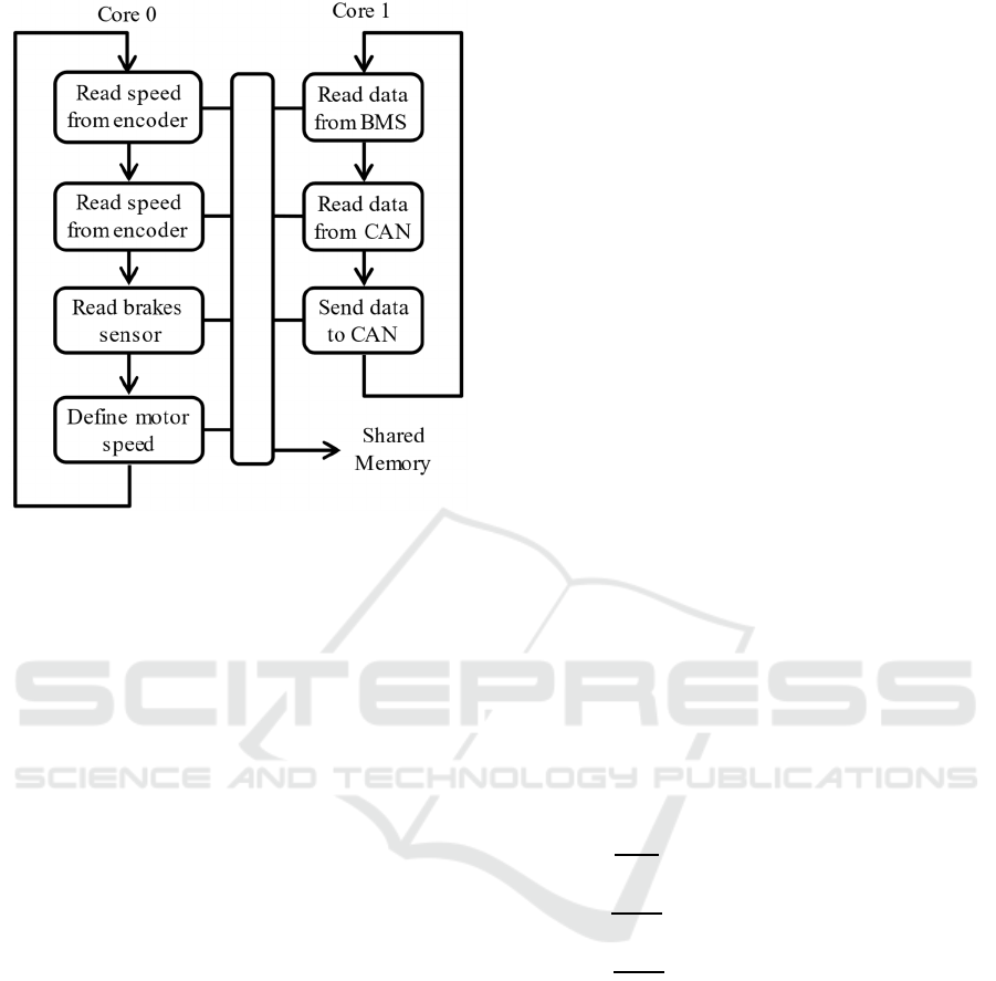
Figure 5: Controller software architecture.
Despite the sequence presented in Figure 5, only
some tasks are performed each cycle. For example, if
the encoder does not send any pulse to calculate
speed, the program will automatically move to the
next task. The same concept applies to all tasks.
The encoder sends pulses to the microcontroller
every time a specific point of the motor is detected
during its rotation. The microcontroller then
calculates the time between these pulses to calculate
the speed. Every time a pulse is detected, the velocity
(v) in meters per second is calculated with the
following equation,
𝑣=
25.4 𝜋 𝐷
𝑡
𝑡
𝑛
⁄
(1)
where n
se
is the number of encoder position sensors,
D is the wheel diameter in inches and t
n
– t
n-1
is the
time between pulses in milliseconds. Using just this
equation to calculate speed would mean that the speed
is not updated in case the vehicle stops. To overcome
this, a timeout needs to be set, sacrificing the
possibility of reading speeds below a specific speed
value. A higher speed value indicates that the
controller will be faster to acknowledge the vehicle
stopped. Motor with more encoder position sensors
will be capable of reading lower speeds than single
encoder position sensor motors. Sacrificing the ability
to read speeds below 0.56 m/s (2.0 km/h) has proven
to be a good balance between speed reading
capability and stopping acknowledgement time
during experimental tests. Solving for t
n
– t
n-1
in
equation 1, the value of 3703 milliseconds is obtained
for a motor with 1 encoder position sensor (n
s
= 1).
The pedal sensor works in a similar way to the
motor encoder. The pedal has a set of magnets that,
when in movement, become close to a fixed Hall
effect sensor, which sends a signal to the
microcontroller. Since the magnets always follow a
circular trajectory, the signal becomes a pulse like the
encoder output signal. Despite the controller not
considering the specific pedaling speed for motor
control, the time between pulses is useful to detect
when the user starts and stops pedaling. The pedal
rotation speed (ω) in rad/s is calculated as
𝜔=
2000 𝜋
𝑡
𝑡
𝑛
⁄
(2
)
where t
m
– t
m-1
is the time between pulses in
milliseconds and n
sp
is the number of magnets in the
pedal sensor. Just like the speed calculation, a timeout
value needs to be set to know when the user stopped
pedaling. A lower value means the controller will take
less to acknowledge the pedals stopped, but the
minimum pedal speed will be higher. For a pedal
sensor with 12 magnets, experimental tests revealed
that a timeout of 750 milliseconds makes a good
balance between pedal stopping acknowledgement
and minimum pedal speed. Solving for ω in equation
2, an angular speed of 0.70 rad/s.
During discharge, the SoC (in percentage) is
calculated through simple segmented functions as
𝑆𝑜𝐶=
⎩
⎪
⎪
⎨
⎪
⎪
⎧
8.3𝑉
𝑛
23.3, 𝑉3.4𝑛
150𝑉
𝑛
505,3.4𝑛
𝑉3.7𝑛
100𝑉
𝑛
320, 𝑉3.7𝑛
(3
)
where V is the measured voltage on the battery
terminals and n
c
is the number of cells in series. This
simplified model was adopted for proof-of concept
only, but more complex methods to calculate the SoC
can be employed (Hassan et al., 2022).
The braking sensors are installed in both brake
levers, and act as normally open switches. Using
either the front brake or rear brake will make the
controller stop the motor assist immediately. For that
reason, the brakes share the same input on the
microcontroller, as illustrated on Figure 6.
VEHITS 2025 - 11th International Conference on Vehicle Technology and Intelligent Transport Systems
38

Figure 6: Braking sensors circuit.
The last task that runs on core 0 is the motor speed
setting task. Depending on the data collected by the
previous tasks, this task will determine the
appropriate motor rotation speed. There are 5
different assistance levels, which are chosen by the
user with a set of buttons connected to the display.
Each assistance level will help the user get to a
specific maximum speed, separated by increments of
5 km/h. The motor will only deliver the specific
assistance level power if the user is pedaling and not
braking. Once the user stops the pedal movement or
brakes, the power is interrupted.
There is also the possibility of no assistance at all,
usually called ‘Level 0’. In this case, the e-bike
becomes a regular bicycle, relying only on the user’s
pedaling to generate motion. In case the user is
walking while carrying his e-bike at his side, there is
a specific mode called ‘Walk mode’ (W). This mode
will set the motor to a speed of 6 km/h, without the
need of pedals to be moving, removing the effort to
carry the e-bike around while walking. Table 1
summarizes the different assistance levels and
specific max speeds.
Table 1: Assistance levels and velocities.
Assistance Level Ma
x
Velocit
y
(km/h)
W
6
0 -
1 5
2 10
3 15
4 20
5 25
The first task that runs on core 1 is the BMS data
retrieving task. The BMS is responsible for
monitoring and managing the battery pack to ensure
safe and efficient operation. It balances the charge
across individual cells, protects against overcharging,
over-discharging, and overheating, and provides data
related to all the cells. Depending on the manufacturer
and model of BMS, the specific details about the
communication protocol may be different, however,
the vast majority of BMS provide their data through
a standard UART communication protocol.
In this work, the BMS that was utilized for
experimental tests only sends data on request. There
are two types of requests: When a type 1 request is
sent to the BMS, it replies with the overall voltage of
the battery, current and temperature. When a type 2
request is sent, the BMS replies with information on
the voltages of each cell of the battery. For each type
of request, the BMS takes around 100ms to reply with
information. Only one request can be processed by
the BMS at a time, so the requests are made
alternately and the update time for each type of data
is 200ms.
The second task running on core 1 is responsible
for handling any information arriving from the CAN
network and writing it on the microcontroller’s
internal memory. The only incoming information is
the level of assistance that the user selects on the
display.
For this work, the CAN protocol J1939 was
selected. Developed by the Society of Automotive
Engineers (SAE), J1939 standardizes messages,
addressing, and diagnostics across vehicle systems,
enabling interoperability between components from
different manufacturers. It defines message
structures, known as Parameter Group Numbers
(PGNs), to organize data like engine speed, vehicle
speed, and fuel levels, and assigns Suspect Parameter
Numbers (SPNs) to specific data points within
messages. J1939 is widely used for real-time data
sharing, diagnostics, and control in multi-component
vehicular systems (Society of Automotive Engineers
[SAE], 2023).
Despite not having all the parameters required for
e-bikes, the J1939 protocol offers the possibility to
use custom PGNs and SPNs. That way, any extra
information that is not listed in the protocol can be
transmitted through the CAN network. After
associating the e-bike’s data with the available SPN
codes, the custom addresses were created.
The last task running on core 1 is responsible for
gathering information from the microcontroller’s
internal memory and sending it to the CAN network.
While some information such as vehicle speed and
level of assistance is useful for the display, the rest of
the data can be useful for external devices. Table 2
lists the SPN codes and their descriptions.
Development of a New Architecture for next Generation e-Bikes
39
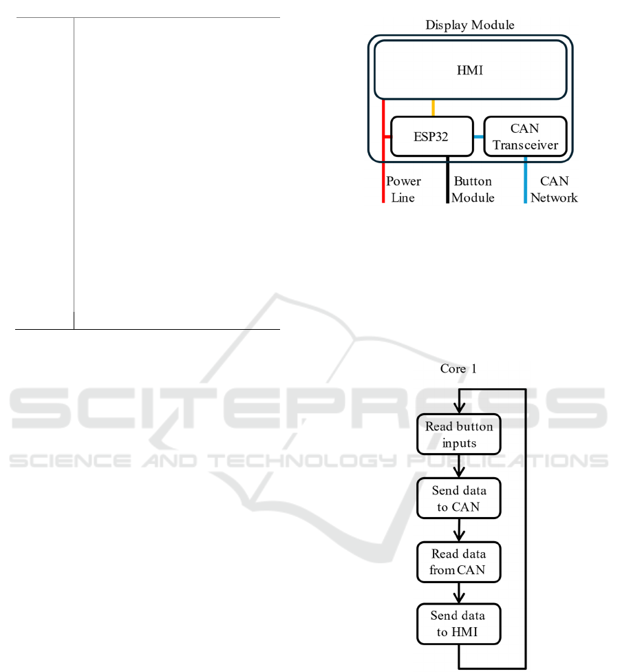
Table 2: CAN SPN codes.
SP
N
Description
84 Wheel-Base
d
Vehicle Spee
d
114 Batter
y
Current
168 Batter
y
Voltage
521 Brake Statu
s
3607 Engine Emergenc
y
Shutdown
10001 Level o
f
assistance
10002 Controller Temperature
10003 Batter
y
Temperature
10010 Cell 1 Voltage
10011 Cell 2 Voltage
10012 Cell 3 Voltage
10013 Cell 4 Voltage
10014 Cell 5 Voltage
10015 Cell 6 Voltage
10016 Cell 7 Voltage
10017 Cell 8 Voltage
10018 Cell 9 Voltage
10019 Cell 10 Voltage
2.2 Display Module Architecture
Following the same design principle as the controller,
the display module architecture adopts an ESP32 as
its microcontroller. The display module will be
responsible for receiving commands from the user
through physical buttons, send and receive data
through the CAN network, and display to the user all
the important information.
2.2.1 Display Module Hardware
The display module is powered by a power line from
the voltage regulator on the controller. Since this
work’s objective is only proof of concept, an HMI
(Human-Machine Interface) is used to display the
relevant information for its ease of use, instead of a
regular display. An HMI allows users to interact with
the system, using display plus controls like buttons or
a touchscreen. A display, in contrast, simply shows
information without enabling user input. In this case,
the display module will not be taking advantage of the
input capabilities of the HMI, as user inputs are
received through physical buttons.
A button module with three buttons identical to
regular e-bike button module is used. There are two
buttons to change the assistance level (Up or Down)
and a general-purpose button that allows the user to
change settings on the display. In the same way as the
controller, a CAN transceiver is necessary to send and
receive messages from the CAN network. Figure 7
illustrates the display module architecture.
Figure 7: Display module architecture and components.
2.2.2 Display Software
Since the display module computational workload is
lighter when compared to the controller’s workload,
only core 1 of the microcontroller is used for the
display module. Figure 8 illustrates the individual
tasks and how they’re sequenced.
Figure 8: Display module tasks and sequencing.
The cycle begins by reading any inputs from the
user through the physical buttons. If the user changes
the assistance level, task 2 will take care of sending
that information through the CAN network. The third
task will check the CAN transceiver module for any
incoming data. In case there is new data, then the last
task will update the information on the HMI.
VEHITS 2025 - 11th International Conference on Vehicle Technology and Intelligent Transport Systems
40
The HMI needs to be set up through an application
provided by the manufacturers. A set of variables are
created and linked to a specific set of pixels on the
HMI’s display. These variables can then be updated
using simple UART communication by the ESP32.
Since the HMI’s touchscreen is not being used, this
communication is not bidirectional, and only the
microcontroller sends information to the HMI. The
structure of the message sent by the microcontroller
may vary depending on the HMI manufacturer.
Figure 9 illustrates the set of variables that will be
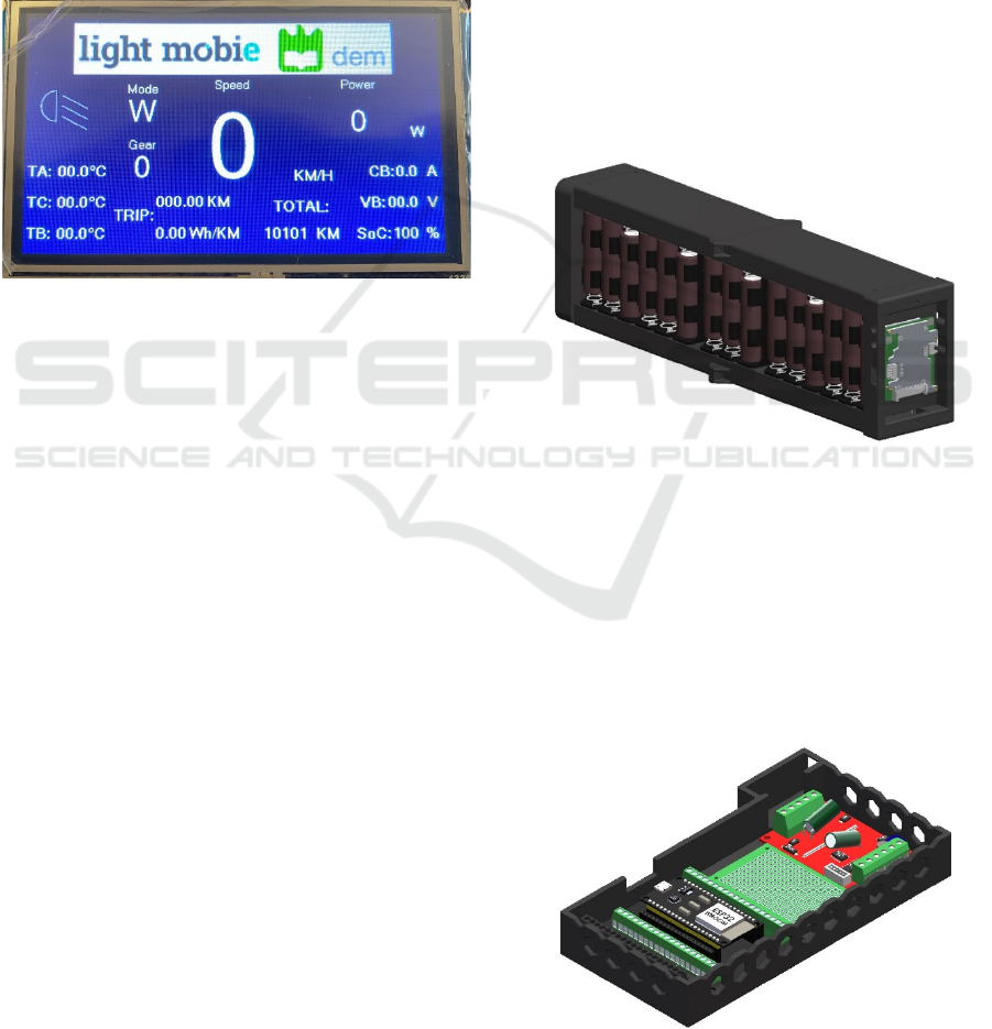
displayed on the screen.
Figure 9: HMI Variables Displayed.
Besides all the information provided by the
controller through the CAN network, the HMI
displays the instant power draw, total energy draw,
distance travelled, and average energy consumption
since the trip started. The instantaneous power draw
(P) in watts is calculated as
𝑃=𝑉𝐼
(4)
where V is the battery’s voltage, and I is the
instantaneous current. The total energy (E
t
) used in
watt-hour (Wh) is calculated with
𝐸
=𝐸
+ 𝑃𝛥𝑡 3600
⁄
(5)
where E
t-1
is the previous total energy, P is the current
power and Δt is the time between calculations. Every
time a new speed is recorded, the distance travelled
(x
t
) in meters per second is calculated with the
previous total travelled distance (x
t-1
), the vehicle’s
speed (v) in meters per second and the time between
calculations (Δt
v
), using equation 5.
𝑥
=𝑥
+𝑣𝛥𝑡
(6)
Finally, the average energy consumption (E
a
) in
watt-hour per kilometer is calculated as
𝐸
=𝐸
𝑥
⁄
(7)
with the total distance in kilometers, in this case.
3 EXPERIMANTAL TESTS
To test the presented concept, an experimental setup
was conceived and built. The conducted experiment’s
objective is to confirm that the proposed system can
replicate the functionality of a regular e-bike, while
allowing the implementation of algorithms and
communication with external devices that can read
the data from the system and send an emergency stop
command if necessary.
To conduct the experiment, an e-bike motor was
installed in a regular bicycle, and three prototypes
were constructed: a controller, a battery with BMS
and a display module. An ESP32 with a CAN
transceiver was used to simulate an external device.
Using 30 individual lithium-ion cells, a battery with
BMS was constructed. Figure 10 shows the 3D model
in CAD software.
Figure 10: Battery 3D model.
A controller housing was designed to
accommodate all the components, and the prototype
was 3D printed. The controller assembly was divided
into 2 levels. The bottom level of the controller
houses the ESP32, the optocouplers module and the
BLDC driver. Besides housing the CAN transceiver
and the power converter, the top level is also utilized
for cable management. In Figure 12 is an illustration
of the controller’s bottom level in CAD software.
Figure 12: Controller’s bottom level.
Development of a New Architecture for next Generation e-Bikes
41
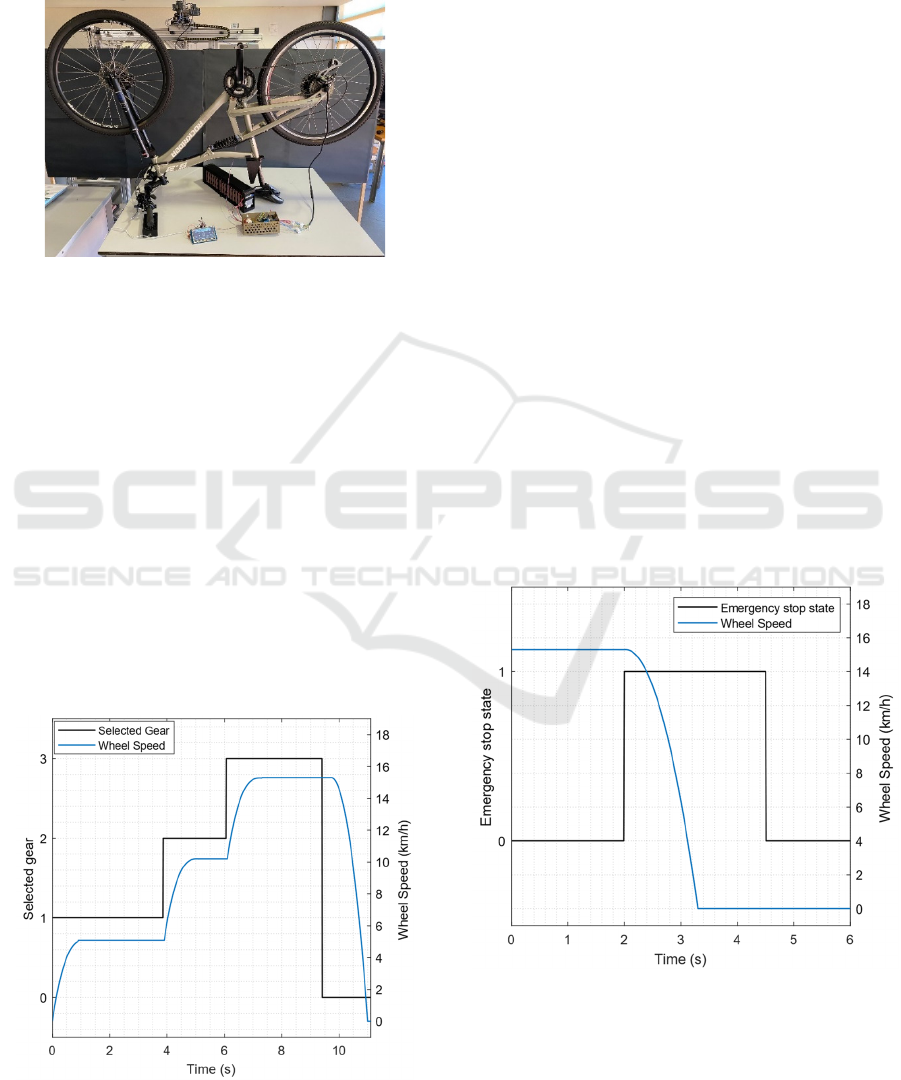
The display module was assembled and connected
to the rest of the system. After assembling all the
devices, the experimental setup was complete and
experimental testing was possible. Figure 14 shows
the whole experimental setup.
Figure 14: Experimental setup.
After building the experimental test setup, several
tests were conducted to evaluate the regular
functionality of the e-bike and its enhanced features.
The first test aimed to verify the basic functionality of
the system under normal operating conditions.
Initially, assistance level 1 was selected, and the
pedals were moved manually. After a few seconds,
assistance level 2 was manually selected. Finally,
assistance level 3 was selected, and after a brief period,
the pedals were brought to a stop, automatically
switching the assistance level to 0. The readings were
performed by an external microcontroller connected to
the bicycle's CAN bus. Measurements of the assistance
level and wheel speed were recorded throughout the
entire duration of the test, which lasted approximately
11 seconds. The data collected during the first test is
presented in Figure 15.
Figure 15: Assistance level and vehicle wheel speed during
test 1.
In Figure 15, the plot clearly shows the transition
between assistance levels and the corresponding
variations in wheel speed, demonstrating the system's
ability to adapt to user input in real-time. Since the
tests were conducted in a laboratory for proof-of-
concept only, the acceleration time between
assistance level changes is relatively small. In a real
use case scenario, the acceleration time is expected to
be substantially larger. When the pedal movement
stops, there is a slight delay in the deceleration of the
motor. This was expected, since it is related to the
acknowledgment time of the pedal’s movement stop.
A second test was performed to evaluate the
system's response to an emergency stop command
issued by an external device, as well as to validate the
integrated safety features of the proposed
architecture. As a security feature, the controller was
programmed to keep the motor disabled even if an
emergency stop command is deactivated. This
ensures that motor operation cannot resume
unintentionally, requiring a full system reset to
unlock the motor.
Initially, the assistance level was set to 3, and the
pedals were manually rotated to simulate normal
operation. An external device then sends a continuous
emergency command via the CAN bus which lasts for
2.5 seconds. The values of the emergency stop
variable and wheel speed were continuously recorded
during the test. The data collected during the second
test is presented in Figure 16.
Figure 16: Emergency stop state and vehicle wheel speed
during test 2.
The results confirm the system's ability to
integrate with external safety mechanisms, since
when an emergency command was detected, the
VEHITS 2025 - 11th International Conference on Vehicle Technology and Intelligent Transport Systems
42
controller immediately halted motor assistance, not
resuming motor operation when the emergency state
was deactivated.
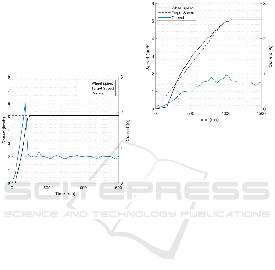
The final test aimed to demonstrate the potential for
improving energy efficiency through the implemen-
tation of algorithms. In this test, the electrical current
through the motor was first recorded during an
acceleration from rest to the speed corresponding to
gear 1. The current and wheel speed readings during
the acceleration can be seen in Figure 17.
Figure 17: Current and wheel speed reading during regular
acceleration.
In this case, when the assistance level is selected
and the pedals move, the microcontroller immediately
sends a command to the motor driver to achieve the
desired speed. The results show an evident current
spike which can waste a significant amount of energy.
To eliminate current spikes during accelerations,
a simple algorithm is proposed. Instead of sending a
fixed speed value to the motor, a simple algorithm can
increase the target speed linearly during a specific
time interval. For proof-of-concept only, a total time
interval of 1 sec was selected for incremental speed
increase. For the same final speed (gear 1) as the
previous current test, the results of an incremental
algorithm can be seen on Figure 18.
As the results from Figure 18 show, utilizing an
incremental speed control algorithm has a positive
impact on energy consumption, since no current
spikes are visible. This example demonstrates the
potential to enhance the e-bike's performance through
embedded algorithms that can monitor and control
not only speed but also other variables like current,
temperature and cooling solutions.
Figure 18: Current and wheel speed reading during
incremental acceleration.
4 CONCLUSIONS
In this work, a new architecture for e-bike systems
was proposed, centered on an open, microcontroller-
based design with a CAN communication bus. This
innovative approach addresses the limitations of
traditional black-box systems by enabling seamless
integration of algorithms, external modules, and
subsystems, thereby fostering adaptability and
enhanced functionality. Several prototypes were built
and used for experimental testing to validate the
system's performance and compliance with current e-
bike legislation. Testing demonstrated the
architecture's practicality, showcasing features such
as emergency stop functionality, real-time data
sharing, and possibility of implementation of power
management algorithms. These results highlight the
system's capability to support the evolving demands
of urban mobility by offering a flexible, efficient, and
connected platform for next-generation e-bike
development.
ACKNOWLEDGEMENTS
This work was developed in the scope of the project
AM2R – “Agenda Mobilizadora para a Inovação
Empresarial do Setor das Duas Rodas” [C644866475-
00000012 – Project n. 15], financed by PRR –
Recovery and Resilience Plan under the Next
Generation EU from the European Union, and by the
Development of a New Architecture for next Generation e-Bikes
43

projects UIDB/00481/2020 and UIDP/00481/2020 -
Fundação para a Ciência e a Tecnologia,
https://doi.org/10.54499/UIDB/00481/2020.
REFERENCES
Fishman, E., & Cherry, C. (2015). E-bikes in the
Mainstream: Reviewing a Decade of Research.
Transport Reviews, 36(1), 72–91. https://doi.org/10.10
80/01441647.2015.1069907.
Mordor Intelligence (2024), Europe e-bike market -
Growth, trends & forecasts up to 2029. Last accessed:
January 22, 2025, available at: https://www.mordorin
telligence.com/industry-reports/europe-e-bike-market.
Boglietti, S., Barabino, B., & Maternini, G. (2021). Survey
on e-Powered Micro Personal Mobility Vehicles:
Exploring Current Issues towards Future
Developments. Sustainability, 13(7), 3692.
https://doi.org/10.3390/su13073692.
Schnieder, M. (2023). Ebike Sharing vs. Bike Sharing:
Demand Prediction Using Deep Neural Networks and
Random Forests. Sustainability, 15(18), 13898.
https://doi.org/10.3390/su151813898.
Nunes, P., Nicolau, C., Santos, J. P., Completo, A. (2020).
From a Traditional Bicycle to a Mobile Sensor in the
Cities. In Proceedings of the 6th International
Conference on Vehicle Technology and Intelligent
Transport Systems - VEHITS pages 81-88.
https://doi.org/10.5220/0009349700810088.
Grama, A., Petreus, D., Baciu, C., Bia, B., Coca, O.,
Socaciu, V. (2018). Smart Bike Improvement Using
Embedded Systems. 2018 41st International Spring
Seminar on Electronics Technology (ISSE), 1–4.
https://doi.org/10.1109/ISSE.2018.8443769.
Andres, J., Kari, T., Kaenel, J.V., Mueller, F.F. (2019). Co-
riding With My eBike to Get Green Lights.
Proceedings of the 2019 ACM Designing Interactive
Systems Conference, pp. 1251 – 1263
https://doi.org/10.1145/3322276.3322307.
Cammin C., Mousavi M.R., Trautwein I., Freymann A.,
Beutelspacher C., Nehrke L., Ludwig S., Kirchheim A.
(2023). Concept for a Real-Time IoT-Architecture for
Collision Avoidance in Smart Cities based on the 5G
Mobile Technology. 2023 IEEE International
Conference on Omni-Layer Intelligent Systems.
https://doi.org/10.1109/COINS57856.2023.10189240.
Arango I., Lopez C., Ceren A. (2021). Improving the
autonomy of a mid-drive motor electric bicycle based
on system efficiency maps and its performance. World
Electric Vehicle Journal, 12 (2), art. no. 59.
https://doi.org/10.3390/wevj12020059.
De La Iglesia, D. H., Villarrubia, G., De Paz, J. F., & Bajo,
J. (2017). Multi-Sensor Information Fusion for
Optimizing Electric Bicycle Routes Using a Swarm
Intelligence Algorithm. Sensors, 17(11), 2501.
https://doi.org/10.3390/s17112501.
Vishnu S., Dash A., Praveena Krishna P.S., Arjun M.,
Jayalakshmi N.S. (2022). Hybrid Control Algorithm for
BLDC Drive Involving Battery and Supercapacitor in
E-bikes. 2022 International Virtual Conference on
Power Engineering Computing and Control:
Developments in Electric Vehicles and Energy Sector
for Sustainable Future. DOI: 10.1109/PECCON5501
7.2022.9851060.
Xie, Z., Jeon, W., Rajamani, R. (2021). Low-density lidar
based estimation system for bicycle protection. IEEE
Transactions on Intelligent Vehicles, 6(1), 67–77.
https://doi.org/10.1109/TIV.2020.3010728.
Zhao, M., Stasinopoulos, S., Yu, Y. (2017). Obstacle
detection and avoidance for autonomous bicycles. In
2017 13th IEEE Conference on Automation Science
and Engineering (CASE) (pp. 1310–1315).
https://doi.org/10.1109/COASE.2017.8256281.
Lightmobie, Lda (2025). Retrieved from:
https://lightmobie.pt/
Xia, C. (2012). Permanent Magnet Brushless DC Motor
Drives and Controls. Wiley-IEEE Press.
ISBN: 9781118188330
European Committee for Standardization. (2017). EN
15194: 2017 Cycles – Electrically power assisted cycles
– EPAC Bicycles. Brussels: CEN.
S. Tuohy, M. Glavin, C. Hughes, E. Jones, M. Trivedi, L.
Kilmartin, (2015) "Intra-Vehicle Networks: A
Review," in IEEE Transactions on Intelligent
Transportation Systems, vol. 16, no. 2, pp. 534-545, ,
https://doi.org/10.1109/TITS.2014.2320605.
Navet N., and Simonot-Lion F., (2008). Automotive
Embedded Systems Handbook. CRC Press.
ISBN: 9780849380266
Maier A., Sharp A., Vagapov Y. (2017). Comparative
analysis and practical implementation of the ESP32
microcontroller module for the internet of things. ITA
2017 - Proceedings of the 7th International
Conference, art. no. 8101926, pp. 143 – 148.
DOI: 10.1109/ITECHA.2017.8101926
Ul Hassan, M., Saha, S., Haque, Md. E., Islam, S.,
Mahmud, A., Mendis, N. (2022). A comprehensive
review of battery state of charge estimation techniques.
Sustainable Energy Technologies and Assessments, 54,
102801. https://doi.org/10.1016/j.seta.2022.102801.
Society of Automotive Engineers (SEA), (2023). Serial
Control and Communications Heavy-Duty Vehicle
Network. Society of Automotive Engineers.
VEHITS 2025 - 11th International Conference on Vehicle Technology and Intelligent Transport Systems
44
