
A Novel Vision Transformer for Camera-LiDAR Fusion Based Traffic
Object Segmentation
Toomas Tahves
1 a
, Junyi Gu
1,2 b
, Mauro Bellone
3 c
and Raivo Sell
1 d
1
Department of Mechanical and Industrial Engineering, Tallinn University of Technology, Estonia
2
Dept. of Computer Science and Engineering, Chalmers University of Technology and University of Gothenburg, Sweden
3
FinEst Centre for Smart Cities, Tallinn University of Technology, Estonia
Keywords:
Dense Vision Transformers, Semantic Segmentation, Sensor Fusion, Residual Neural Network.
Abstract:
This paper presents Camera-LiDAR Fusion Transformer (CLFT) models for traffic object segmentation, which
leverage the fusion of camera and LiDAR data using vision transformers. Building on the methodology of
visual transformers that exploit the self-attention mechanism, we extend segmentation capabilities with addi-
tional classification options to a diverse class of objects including cyclists, traffic signs, and pedestrians across
diverse weather conditions. Despite good performance, the models face challenges under adverse conditions
which underscores the need for further optimization to enhance performance in darkness and rain. In summary,
the CLFT models offer a compelling solution for autonomous driving perception, advancing the state-of-the-
art in multimodal fusion and object segmentation, with ongoing efforts required to address existing limitations
and fully harness their potential in practical deployments.
1 INTRODUCTION
This work extends our previous work on camera-
LiDAR fusion transformer (CLFT) (Gu et al., 2024),
which utilizes the encoder-decoder structure of a
transformer network but uses a novel progressive-
assemble strategy of vision transformers. We elab-
orate on the CLFT methodology and extend segmen-
tation with additional classification options. Our goal
is to outperform existing CNN and visual transformer
models by leveraging camera and LiDAR data fusion.
Transformers (Vaswani et al., 2023), initially in-
troduced for language models, rely on a mechanism
called self-attention to process input data patches.
This allows models to globally weigh the importance
of different parts of input data simultaneously, thus
improving computation efficiency. Since transform-
ers do not contain information about the order of in-
put tokens, positional encodings are added to input
embeddings to retain information which is crucial to
remember in tasks such as language translation and
image recognition.
Vision transformers (ViT) (Dosovitskiy et al.,
2021) apply the transformer architecture to image
a
https://orcid.org/0009-0008-0050-2146
b
https://orcid.org/0000-0002-5976-6698
c
https://orcid.org/0000-0003-3692-0688
d
https://orcid.org/0000-0003-1409-0206
data by dividing images into patches and treating
each patch as a token which allows models to cap-
ture global context and relationships between dif-
ferent parts of an image. Dense prediction trans-
formers (DPT) (Ranftl et al., 2021) process im-
age patches similarly to ViTs but focus on generat-
ing pixel-level predictions by leveraging the strengths
of transformers in capturing long-range dependencies
and contextual information. Our hypothesis is that
the combination of ViT and DPT can grab dependen-
cies in the data improving the interpretation of less-
represented classes in consideration that autonomous
driving datasets are strongly unbalanced to vehicles.
Following this line of research, our work provides
the following main contributions:
• We enhanced the CLFT model to handle a broader
spectrum of traffic objects, including cyclists,
signs, and pedestrians.
• Through extensive testing, we demonstrated that
our model achieves superior accuracy and per-
formance metrics compared to other visual trans-
former models.
• By leveraging the strengths of multi-modal sen-
sor fusion and the multi-attention mechanism, the
CLFT model proves to be a solution for diverse
environmental conditions, including challenging
weather scenarios.
566
Tahves, T., Gu, J., Bellone, M. and Sell, R.
A Novel Vision Transformer for Camera-LiDAR Fusion Based Traffic Object Segmentation.
DOI: 10.5220/0013239000003890
Paper published under CC license (CC BY-NC-ND 4.0)
In Proceedings of the 17th International Conference on Agents and Artificial Intelligence (ICAART 2025) - Volume 2, pages 566-573
ISBN: 978-989-758-737-5; ISSN: 2184-433X
Proceedings Copyright © 2025 by SCITEPRESS – Science and Technology Publications, Lda.

2 RELATED WORK
The fusion of camera and LiDAR data is a widely re-
searched topic in multimodal fusion with applications
in object detection and segmentation. Various tech-
niques have been proposed over the years to solve
these problems, (Cui et al., 2022) proposed the fol-
lowing categorization options: signal-level, feature-
level, result-level, and multi-level fusion. Signal-level
fusion depends on raw sensor data, while it is suitable
for depth completion (Cheng et al., 2019) (Lin et al.,
2022) and landmark detection (Lee and Park, 2021)
(Caltagirone et al., 2018), it still suffers from loss of
texture information. Voxel grid or 2D projection are
used to represent LiDAR data as feature maps, for in-
stance, the implementation of VoxelNet (Zhou and
Tuzel, 2017) uses raw point clouds as voxels before
fusing LiDAR data with camera pixels. Result-level
fusion increases accuracy by merging prediction re-
sults from different model outputs (Jaritz et al., 2020)
(Gu et al., 2018). Through reviewing the literature, it
is possible to observe that the recent trend is to shift
towards multi-level fusion, which represents a com-
bination of all other fusion strategies. The compu-
tational complexity resulting from LiDAR 3D data
is tackled by reducing the dimensionality to a two-
dimensional image to exploit the existing image pro-
cessing methods. Our work uses a transformer-based
network for integrating camera and LiDAR data in a
cross-fusion strategy in the decoder layers.
The attention mechanism introduced in the trans-
former architecture in (Vaswani et al., 2023) has
a tremendous impact in various fields, especially in
natural language processing (Xiao and Zhu, 2023)
and computer vision. One notable variant is the vi-
sion transformer (ViT) (Dosovitskiy et al., 2021),
which excels in autonomous driving tasks by han-
dling global contexts and long-range dependencies.
Perceiving the surrounding area in a two-dimensional
plane primarily involves extracting information from
camera images with notable works like bird eye view
transformers for road surface segmentation presented
in (Zhu et al., 2024). Other recent approaches include
lightweight transformers for lane shape prediction
and combined semantic and instance segmentation
(Lai-Dang, 2024). Three-dimensional autonomous
driving perception is an extensively researched topic
focusing on object detection and segmentation. In
(Wang et al., 2021) DETR3D, the authors present a
multi-camera object detection method, unlike others
that rely on monocular images, it extracts 2D features
from images and uses 3D object queries to link fea-
tures to 3D positions via camera transformation ma-
trices. FUTR3D (Chen et al., 2023) employs a query-
based Modality-Agnostic Feature Sampler (MAFS),
together with a transformer decoder with a set-to-set
loss for 3D detection, thus avoiding using late fusion
heuristics and post-processing tricks. BEVFormer
(Li et al., 2022) improves object detection and map
segmentation with spatial and temporal attention lay-
ers via spatiotemporal transformers.
Recent works emphasize the fusion of camera and
LiDAR data for enhanced perception. CLFT models,
for instance, process LiDAR point clouds as image
views to achieve 2D semantic segmentation, bridging
gaps in multi-modal semantic object segmentation.
3 METHODOLOGY
In this section, we elaborate on the detailed struc-
ture of the CLFT network in the sequential order of
data processing, aiming to provide an exclusive in-
sight into how the sensory data flows in the network,
thus, benefits the understanding and reproducibility of
our work.
The CLFT network achieves the camera-LiDAR
fusion by progressively assembling features from
each modality first and then conducting the cross-
fusion at the end. Figuratively, the CLFT network
has two directions to process the input camera and
LiDAR data in parallel; the integration of two modal-
ities happens at the ‘fusion’ stage in the network’s de-
coder block. In general, there are three steps in the
entire process. The first step is pre-processing the in-
put, which embeds the image-like data to the learn-
able transformer tokens; the second step closely fol-
lows the protocols of ViT (Dosovitskiy et al., 2021)
encoders to encode the embedded tokens; the last step
is the post-processing of the data, which progressively
assembles and fuses the feature representations to ac-
quire segmentation predictions. The details of the
three steps are described in the following three sub-
sections.
3.1 Embedding
The camera and LiDAR input data pre-processing is
independent and in parallel. As mentioned in Sec-
tion 1, we select the LiDAR processing strategy to
project the point cloud data onto the camera plane,
thus attaining the LiDAR projection images. For deep
multi-modal sensor fusion, the transition from differ-
ent inputs to a unified modality simplifies the network
structure and minimizes the fusion errors.
As shown in Fig. 1, there are a total of four steps
in the embedding module. The first step is resiz-
ing the camera and LiDAR matrices to r = 384 and
A Novel Vision Transformer for Camera-LiDAR Fusion Based Traffic Object Segmentation
567
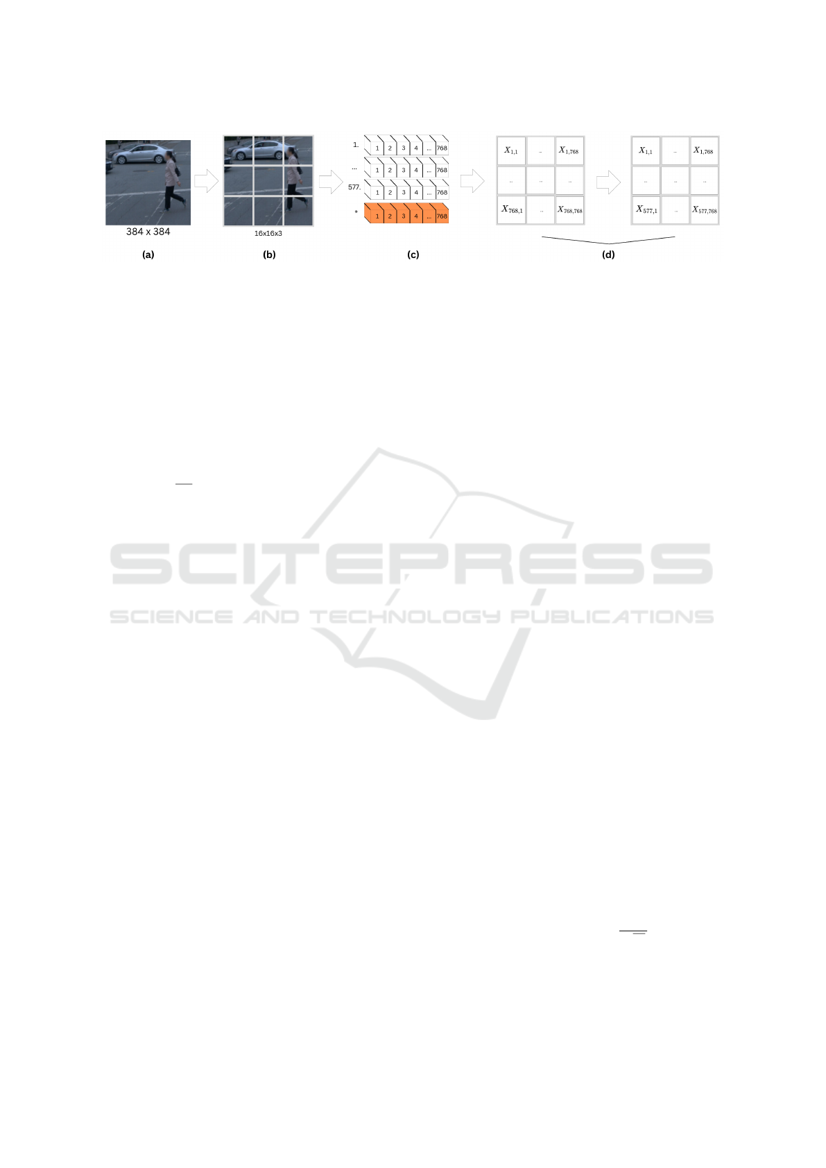
Figure 1: Embedding process for camera and LiDAR data. (a) The original image is resized to a resolution of 384 ×384 to
standardize the input dimensions. (b) The input image is segmented into non-overlapping fixed-size patches of 16×16 pixels.
(c) Patches are flattened into one-dimensional embedded vectors, with an additional positional embedding (colored in orange)
added to provide spatial information. (d) The combined patch embeddings are processed through Multilayer Perceptrons
(MLPs) with dimensions E =
¯
D ×D, resulting in a matrix that serves as the input for the transformer encoder. The whole
figure is based on the CLFT-Base variant.
c = 384, where r is the number of rows and c is the
number of columns. The second step segments the
input image into non-overlapping fixed-size patches.
The size of each patch p in pixels is 16 ×16. There-
fore, the dimension
¯
D of the token representing one
patch is 16 ×16 ×3 = 768. In the third step, patches
are flattened into one-dimensional embedded vectors
X of length
r∗c
p∗p
= 576 to serve as input tokens for
the transformer model. Since transformers inher-
ently lack the capacity to comprehend spatial and two-
dimensional neighborhood structure relationships be-
tween patches, we incorporate an extra positional em-
bedding into each patch (Dosovitskiy et al., 2021).
The additional embedding provides the network with
essential information regarding the relative spatial po-
sitions of the patches within the original image. Se-
quentially, in the last step, we pass the combined
patch embeddings through the Multilayer Perceptrons
(MLPs) with dimensions of E =
¯
D ×D. D indicates
the network’s various feature dimensions for different
network parameter configurations. The resulting ma-
trix X ×E is the input of the transformer encoder for
further learning and processing.
3.2 Encoder
The essence of the transformer encoder is the Multi-
Head Self-Attention (MHSA) mechanism (Vaswani
et al., 2023), which allows the network to weigh the
importance of each patch relative to each other. With
the assistance of MHSA, the neural networks effec-
tively capture global dependencies and information
by computing attention scores between all pairs of
patches. Moreover, these scores are used to generate
weighted sums of the patch embeddings. The encoder
output consists of embedding matrices, each corre-
sponding to a patch in the original image.
Figure 2 illustrates the detailed process of our
CLFT encoder. The input of the encoder is the re-
sulting matrix X
′
= X × E from the previous em-
bedding step (see Fig. 2(a)). The matrix X
′
con-
tains the image’s patch and position embeddings, as
well as the learnable class tokens. The dimension
of the X
′
is (576 + 1) ×768, which means there are
576 patch embeddings and one extra position embed-
ding. This approach is inspired by BERTs tokeniza-
tion method, which uses similar embeddings to cap-
ture contextual information within text (Devlin et al.,
2019). The multi-head X
′
matrix is then reshaped into
577 ×3 ×768, which represents a Query, Key and,
Value (QKV) matrix, respectively. Equation 1 shows
the multi-head attention H calculation in this step.
H(Q, K, V ) =
N
M
i=1
h
i
W
O
(1)
where
L
means concatenation of head vectors side
by side with each other, and W
O
is the weight matrix
used to linearly transform the concatenated outputs.
Each head h
i
is calculated individually using its own
set of projection matrices as follows:
h
i
= A(QW
Q
i
, KW
K
i
, VW
V
i
) (2)
where A denotes the attention mechanism to the
queries (Q), keys (K), and values (V ). Projection
matrices W
Q
i
, W
K
i
, and W
V
i
for the i-th head are cal-
culated as follows:
W
Q
i
= R
(d
m
×d
k
)
W
K
i
= R
(d
m
×d
k
)
W
V
i
= R
(d
m
×d
v
)
(3)
The Softmax attention mechanism follows the
equation 4:
A(Q, K, V ) = so f tmax(
QK
T
√
d
k
)V (4)
where term QK
T
represents the dot product of the
queries and the transposed keys, generating a sim-
ilarity score between each query-key pair. Square
ICAART 2025 - 17th International Conference on Agents and Artificial Intelligence
568
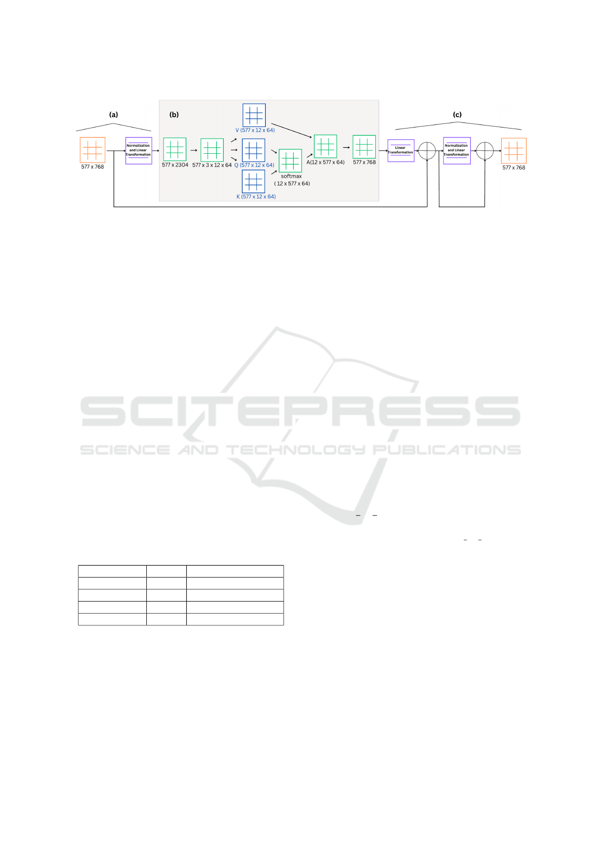
Figure 2: Encoder process. (a) The output from embedding is normalized and passed through linear layers into the multi-head
attention block. (b) The matrix is split into KQV matrices, upon which SoftMax and attention operations are performed. The
KQV matrices are then reshaped into a single matrix. (c) Finally, linear operations are executed, and the result is processed
through the MLP block.
root of the key dimension d
k
prevents the dot product
from becoming too large, which stabilizes the gradi-
ents during training. The Softmax function is applied
to the scaled similarity scores, converting them into
attention weigths, which determine the importance of
each key-value pair for the given query. Finally, the
attention weights are used to compute a weighted sum
of the values V , producing final output of the attention
mechanism for each head.
The QKV matrices are then reshaped into N ×
577 ×64, where N stands for the number of layers
defined in CLFT configuration (as shown in Table 1).
At last, the metrics go though the normalization and
MLP layers to be the input of CLFT decoder (Fig.
2(c)).
Table 1 outlines four potential configuration op-
tions for CLFT encoder. The names follow the
ViT conventions. Each configuration features prede-
fined transformer layers and a feature dimension D
with fixed-size tokens. The CLFT-Hybrid configu-
ration distinguishes itself from the others by using a
ResNet50 residual network (He et al., 2015) to con-
vert 768 ×768 images into 14 ×14 patches, then flat-
tened into one-dimensional vectors of size 196.
Table 1: CLFT configuration variants.
Type Layers Feature dimension D
CLFT-Base 12 768
CLFT-Large 24 1024
CLFT-Huge 32 1280
CLFT-Hybrid 12 768
3.3 Decoder
The decoder module processes the tokens from en-
coder layers to progressively assemble the feature
representations into a 3D matrix. This matrix can
be visualized as an image to make predictions. We
extend the three-stage reassembly operation initially
proposed in the (Ranftl et al., 2021), including data
reading, concatenating, and resampling, with the ex-
tra stage to execute the cross-fusion of camera and
LiDAR data.
In the first stage of reassembly, shown in Fig. 3(a),
we append a special classification token to a set of
N tokens, potentially capturing global information.
(Ranftl et al., 2021) have evaluated three different
variants of this mappings:
• One that ignores the special class token and pro-
cesses only the individual tokens.
• One that propagates information from the class to-
ken to all other tokens.
• One that concatenates the class token to all other
tokens, then projects the combined representation
through a linear layer followed by the GELU ac-
tivation function to introduce non-linearity.
Figure 3(b) shows the second stage of the decoder.
A total amount of N tokens are shaped into an image-
like feature map with the aid of position tokens. The
feature map with D channels is concatenated into a
result R =
r
p
x
c
p
x D.
Figure 3(c) illustrates the third and last stage. The
feature maps is first scaled to size R =
r
s
x
c
s
x
ˆ
D, where
ˆ
D is set as 256 in all experiments. Features from early
layers are resampled at higher resolutions, while fea-
tures from deeper layers of the transformer are re-
sampled at lower resolutions. The CLFT-Base vari-
ant uses layers l = {3, 6, 9, 12}, and the CLFT-Large
variant utilizes layers l = {5, 12, 18, 24} to extract
features. The CLFT-Hybrid variant employs ResNet
layers for initial feature extraction and incorporates
transformer layers l = {9, 12} for deeper feature rep-
resentation. The scaling coefficients s is {4, 8, 16, 32}.
In the last cross-fusion stage, camera and LiDAR
features are combined from feature maps in paral-
lel. Extracted feature maps are combined using the
RefineNet-based feature fusion method, which em-
ploys two residual convolution units (RCUs) in a se-
quence. Results from camera and LiDAR representa-
A Novel Vision Transformer for Camera-LiDAR Fusion Based Traffic Object Segmentation
569
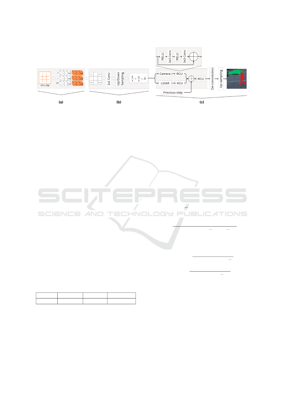
Figure 3: Decoder process. (a) The input tensor, representing data, is concatenated with classification tokens. (b) These
tokens are then concatenated based on their positional information, yielding an image-like representation. Two convolution
operations, along with up-sampling and down-sampling, are applied. (c) Cross-fusion is applied to combine camera and
LiDAR data, progressively integrating outputs from residual computation units from previous steps. The final predicted
segmentation is computed through deconvolution and up-sampling blocks.
tions are summed from the previous fusion stage and
passed through another RCU. The output of the last
RCU is passed to a de-convolutional layer and up-
sampled to compute the predicted segmentation.
4 DATASET CONFIGURATION
Waymo Open Datset (WOD) is designed to aid re-
searchers in autonomous driving. It includes data
from camera and LiDAR sensors which are collected
in urban and suburban environments under diverse
driving conditions. It contains labels for 4 object
classes - vehicles, pedestrians, cyclists, and signs. We
have manually partitioned the dataset into four sub-
sets: dry day, rainy day, dry night, and rainy night,
and the amount of frames per subset is shown in Ta-
ble 2.
We use intersection over union (IoU) to evaluate
the performance of the model along with values of
precision and recall. IoU computation is extended to
validate multi-class semantic segmentation by assign-
ing pixel values to void and excluding them from final
validation. We compare ground truth (Waymo label
values) to the output of the CLFT model to measure
the performance of our work.
Table 2: Frame count per subset in WOD.
Dry day Rainy day Dry night Rainy night
14940 4520 1640 900
4.1 Metrics
We use the intersection over union (IoU) as the pri-
mary indication to evaluate the performance of our
networks. In addition, we provide the results of pre-
cision and recall. The IoU is primarily used in ob-
ject detection applications, in which the output is the
bounding box around the object. We modify the ordi-
nary IoU algorithm to fit the multi-class pixel-wise se-
mantic object segmentation. Given a set of predefined
semantic classes L denoted by L = {0, 1, ..., L −1}.
Each pixel in the image can be represented as a pair
(p
L
, g
L
), where p
L
and g
L
indicate the prediction and
ground-truth class, respectively. The performance of
the networks is measured by the statistics of the num-
ber of pixels that have identical classes indicated in
prediction and ground truth. Not all pixels have a
valid label, therefore ambiguous pixels that fall out
of the class list are assigned as void and not counted
in the evaluation. The IoU of each class is given by
Equation 5, where L means the non-identical class.
IoU
L
=
∑
(p
L
g
L
)
∑
(p
L
g
L
) +
∑
(p
L
g
L
) +
∑
(p
L
g
L
)
(5)
Correspondingly, the precision and recall are ob-
tained by Equation 6 and 7.
Precision
L
=
∑
(p
L
g
L
)
∑
(p
L
g
L
) +
∑
(p
L
g
L
)
(6)
Recall
L
=
∑
(p
L
g
L
)
∑
(p
L
g
L
) +
∑
(p
L
g
L
)
(7)
5 EXPERIMENTAL RESULTS
5.1 Experimental Setup
The transformer-based networks were trained on
servers equipped with Nvidia A100 80GB graphics
cards. Each training session utilized a batch size of
24, running for up to 400 epochs. Early stopping cri-
teria were implemented to prevent over-fitting and to
ensure efficient use of computational resources.
ICAART 2025 - 17th International Conference on Agents and Artificial Intelligence
570
Table 3: Performance comparison of CLFT-Hybrid method during various weather conditions.
IoU Precision Recall
Cyclist Pedestrian Sign Cyclist Pedestrian Sign Cyclist Pedestrian Sign
Dry day
Camera 64.17 67.88 45.48 83.79 79.99 65.41 73.27 81.76 59.88
LiDAR 64.06 68.21 45.22 83.41 79.84 64.45 73.41 82.41 60.24
Camera+LiDAR 60.96 67.75 45.09 82.73 79.42 61.97 69.86 82.17 62.34
Rainy day
Camera 70.75 61.98 35.49 86.19 80.19 68.98 79.80 73.18 42.23
LiDAR 73.76 62.84 37.05 89.53 80.79 68.02 80.73 73.89 44.86
Camera+LiDAR 72.63 62.50 37.82 87.27 79.84 62.30 81.24 74.22 49.03
Dry night
Camera 66.11 66.11 32.82 83.60 81.48 56.74 75.96 77.80 43.77
LiDAR 66.95 66.87 32.70 87.13 80.69 57.23 74.30 79.61 43.27
Camera+LiDAR 61.55 65.68 31.87 79.06 79.80 50.52 73.53 78.78 46.33
Rainy night
Camera 16.38 43.57 40.45 42.30 66.13 64.81 21.10 56.09 51.83
LiDAR 50.11 49.54 39.04 71.10 64.22 59.07 62.92 68.42 53.53
Camera+LiDAR 63.41 48.13 37.42 79.94 70.40 55.28 75.41 60.33 53.67
The dataset was divided into three parts: 60%
for training, 20% for validation, and 20% for testing.
This distribution ensures a balanced approach, allow-
ing the model to learn effectively, validate its perfor-
mance during training, and be evaluated on unseen
data to assess its generalization capabilities.
A total of nine training sessions were conducted,
each with different network parameters: CLFT-Base,
CLFT-Large, and CLFT-Hybrid. Separate training
sessions were performed for LiDAR-only, camera-
only, and cross-fusion of camera+LiDAR data to
comprehensively evaluate the performance across dif-
ferent sensor configurations.
5.2 Varying Weather Conditions
We conducted an analysis of the network performance
across four distinct weather conditions: dry day, rainy
day, dry night, and rainy night. The results of the
CLFT-Hybrid method under these various conditions
are summarized in Table 3.
In dry day conditions, the performance of the
CLFT-Hybrid model using LiDAR alone (IoU: 64%
for cyclists, 68% for pedestrians) was comparable to
using camera data alone (IoU: 64% for cyclists, 68%
for pedestrians) and slightly better than the combined
data.
During rainy day conditions, LiDAR data outper-
formed camera data (IoU: 74% for cyclists, 63% for
pedestrians vs. 71% for cyclists, 62% for pedestri-
ans). This is an expected result as the camera is
blurred by rain, while LiDARs are typically less af-
fected. Combined data was competitive, with IoU of
73% for cyclists and 63% for pedestrians, showing
LiDAR’s resilience against visual noise and low-light
environments.
Under dry night conditions, LiDAR data per-
formed better than both combined and camera data
alone (IoU: 67% for cyclists, 67% for pedestrians vs.
66% for cyclists and pedestrians with camera), pre-
senting LiDAR’s advantage in low light conditions.
Under rainy night conditions, the combined Li-
DAR+Camera data yielded the highest performance
(IoU: 63% for cyclists, 48% for pedestrians vs. 50%
for cyclists and 50% for pedestrians with LiDAR
alone). Cross-fusion effectively leveraged comple-
mentary information, providing depth and texture de-
tails.
5.3 Varying Network Configurations
The performance metrics of different CLFT configu-
rations under dry day conditions are summarized in
Table 4. The CLFT-Base configuration showed that
using either camera or LiDAR alone provides compa-
rable results, but combining them did not yield sig-
nificant improvements. The CLFT-Large configura-
tion benefited from higher precision, especially when
combining data sources, suggesting better accuracy in
identifying objects, though IoU did not significantly
improve. The CLFT-Hybrid configuration performed
the best overall, particularly using either camera data
alone or LiDAR data alone. This model effectively
leverages the strengths of both data types, with the
fusion of both data sources yielding high recall for
signs.
A Novel Vision Transformer for Camera-LiDAR Fusion Based Traffic Object Segmentation
571

Table 4: Performance metrics under dry day conditions for different CLFT configurations.
Cyclist Pedestrian Sign
IoU Precision Recall IoU Precision Recall IoU Precision Recall
CLFT-Base C 50.07 84.72 55.04 65.71 80.56 78.09 41.27 66.46 52.13
CLFT-Base L 47.01 84.27 51.53 64.06 78.60 77.59 39.76 63.15 51.78
CLFT-Base C+L 48.31 80.48 54.73 65.11 77.85 79.92 41.33 61.35 55.88
CLFT-Large C 53.50 83.61 59.77 66.03 82.11 77.12 41.17 68.81 50.61
CLFT-Large L 53.91 84.53 59.81 66.31 80.06 79.43 41.44 64.49 53.70
CLFT-Large C+L 53.58 85.11 59.12 66.10 82.28 77.07 41.90 70.07 51.03
CLFT-Hybrid C 64.17 83.79 73.27 67.88 79.99 81.76 45.48 65.41 59.88
CLFT-Hybrid L 64.06 83.41 73.41 68.21 79.84 82.41 45.22 64.45 60.24
CLFT-Hybrid C+L 60.96 82.73 69.86 67.75 79.42 82.17 45.09 61.97 62.34
5.4 Comparison to Other Networks
We compared our results to those of traditional Fully
Convolutional Networks (FCN) (Gu et al., 2022) and
panoptic networks as presented in (Gu et al., 2024).
The CLFT-Hybrid achieved higher IoU scores (e.g.,
64% for cyclists and 68% for pedestrians in dry day
conditions) compared to typical FCN and panoptic
networks, which often struggle with complex scenes
and poor visibility. Unlike FCNs and panoptic net-
works that rely on single modalities, the CLFT effec-
tively combines LiDAR and camera data, enhancing
performance, especially in challenging scenarios like
rainy nights (IoU: 63% for cyclists).
6 CONCLUSION
In this paper, we demonstrated the effectiveness of
Camera-LiDAR Fusion Transformer (CLFT) mod-
els in achieving successful object segmentation by
leveraging sensor cross-fusion and the transformer’s
multi-attention mechanism. The CLFT-Hybrid model
showed remarkable improvements in segmentation
accuracy for cyclists, pedestrians, and traffic signs.
The CLFT models maintained high performance
across a variety of weather conditions, including day,
rain, and night scenarios. By combining the strengths
of both LiDAR and camera data, the CLFT model ef-
fectively utilized cross-fusion to enhance overall per-
formance. The transformer’s multi-attention mecha-
nism enabled the CLFT models to focus on relevant
features and improve object detection and segmenta-
tion accuracy.
Despite these promising results, several chal-
lenges remain. The CLFT models exhibited vari-
ability in performance under adverse weather condi-
tions. For instance, while LiDAR alone performed
well in fair conditions, the fusion of LiDAR and cam-
era data sometimes led to suboptimal results. The
models showed decreased performance in night and
rainy conditions. The CLFT models, especially larger
configurations, require significant computational re-
sources, which poses challenges for real-time imple-
mentation in resource-constrained environments.
Future work should focus on improving the accu-
racy of CLFT models in challenging environments,
exploring more data fusion techniques, and integrat-
ing additional sensor modalities to further enhance
overall performance.
ACKNOWLEDGMENT
Part of the research has received funding from the fol-
lowing grants: the European Union’s Horizon 2020
Research and Innovation Programme project Finest
Twins (grant No. 856602) and AI-Enabled Data Life-
cycles Optimization and Data Spaces Integration for
Increased Efficiency and Interoperability PLIADES,
grant agreement No. 101135988.
REFERENCES
Caltagirone, L., Bellone, M., Svensson, L., and Wahde, M.
(2018). Lidar-camera fusion for road detection using
fully convolutional neural networks.
Chen, X., Zhang, T., Wang, Y., Wang, Y., and Zhao, H.
(2023). Futr3d: A unified sensor fusion framework
for 3d detection.
Cheng, X., Wang, P., Guan, C., and Yang, R. (2019).
Cspn++: Learning context and resource aware convo-
lutional spatial propagation networks for depth com-
pletion.
Cui, Y., Chen, R., Chu, W., Chen, L., Tian, D., Li, Y.,
and Cao, D. (2022). Deep learning for image and
point cloud fusion in autonomous driving: A review.
IEEE Transactions on Intelligent Transportation Sys-
tems, 23(2):722–739.
Devlin, J., Chang, M.-W., Lee, K., and Toutanova, K.
(2019). Bert: Pre-training of deep bidirectional trans-
formers for language understanding.
ICAART 2025 - 17th International Conference on Agents and Artificial Intelligence
572

Dosovitskiy, A., Beyer, L., Kolesnikov, A., Weissenborn,
D., Zhai, X., Unterthiner, T., Dehghani, M., Minderer,
M., Heigold, G., Gelly, S., Uszkoreit, J., and Houlsby,
N. (2021). An image is worth 16x16 words: Trans-
formers for image recognition at scale.
Gu, J., Bellone, M., Pivo
ˇ
nka, T., and Sell, R. (2024). Clft:
Camera-lidar fusion transformer for semantic segmen-
tation in autonomous driving. IEEE Transactions on
Intelligent Vehicles, pages 1–12.
Gu, J., Bellone, M., Sell, R., and Lind, A. (2022). Object
segmentation for autonomous driving using iseauto
data. Electronics, 11(7).
Gu, S., Lu, T., Zhang, Y., Alvarez, J. M., Yang, J., and
Kong, H. (2018). 3-d lidar + monocular camera:
An inverse-depth-induced fusion framework for urban
road detection. IEEE Transactions on Intelligent Ve-
hicles, 3(3):351–360.
He, K., Zhang, X., Ren, S., and Sun, J. (2015). Deep resid-
ual learning for image recognition.
Jaritz, M., Vu, T.-H., de Charette, R.,
´
Emilie Wirbel, and
P
´
erez, P. (2020). xmuda: Cross-modal unsupervised
domain adaptation for 3d semantic segmentation.
Lai-Dang, Q.-V. (2024). A survey of vision transformers in
autonomous driving: Current trends and future direc-
tions.
Lee, J.-S. and Park, T.-H. (2021). Fast road detection by
cnn-based camera–lidar fusion and spherical coordi-
nate transformation. IEEE Transactions on Intelligent
Transportation Systems, 22(9):5802–5810.
Li, Z., Wang, W., Li, H., Xie, E., Sima, C., Lu, T., Yu, Q.,
and Dai, J. (2022). Bevformer: Learning bird’s-eye-
view representation from multi-camera images via
spatiotemporal transformers.
Lin, Y., Cheng, T., Zhong, Q., Zhou, W., and Yang, H.
(2022). Dynamic spatial propagation network for
depth completion.
Ranftl, R., Bochkovskiy, A., and Koltun, V. (2021). Vision
transformers for dense prediction.
Vaswani, A., Shazeer, N., Parmar, N., Uszkoreit, J., Jones,
L., Gomez, A. N., Kaiser, L., and Polosukhin, I.
(2023). Attention is all you need.
Wang, Y., Guizilini, V., Zhang, T., Wang, Y., Zhao, H., and
Solomon, J. (2021). Detr3d: 3d object detection from
multi-view images via 3d-to-2d queries.
Xiao, T. and Zhu, J. (2023). Introduction to transformers:
an nlp perspective.
Zhou, Y. and Tuzel, O. (2017). Voxelnet: End-to-end learn-
ing for point cloud based 3d object detection.
Zhu, Y., Jia, X., Yang, X., and Yan, J. (2024). Flatfu-
sion: Delving into details of sparse transformer-based
camera-lidar fusion for autonomous driving.
A Novel Vision Transformer for Camera-LiDAR Fusion Based Traffic Object Segmentation
573
