
Towards Ubiquitous Mapping and Localization
for Dynamic Indoor Environments
Halim Djerroud
1
, Nico Steyn
2
, Olivier Rabreau
1
, Patrick Bonnin
1
and Abderraouf Benali
1
1
Universit
´
e Paris-Saclay, UVSQ, LISV, 78140, V
´
elizy-Villacoublay, France
2
Tshwane University of Technology, Department of Electrical Engineering, Pretoria, South Africa
Keywords:
UbiSLAM, Ubiquitous Mapping, SLAM, Dynamic Indoor Environment.
Abstract:
We present UbiSLAM, an innovative solution for real-time mapping and localization in dynamic indoor en-
vironments. By deploying a network of fixed RGB-D cameras strategically throughout the workspace, UbiS-
LAM addresses limitations commonly encountered in traditional SLAM systems, such as sensitivity to envi-
ronmental changes and reliance on mobile unit sensors. This fixed-sensor approach enables real-time, com-
prehensive mapping, enhancing the localization accuracy and responsiveness of robots operating within the
environment. The centralized map generated by UbiSLAM is continuously updated, providing robots with an
accurate global view, which improves navigation, minimizes collisions, and facilitates smoother human-robot
interactions in shared spaces. Beyond its advantages, UbiSLAM faces challenges, particularly in ensuring
complete spatial coverage and managing blind spots, which necessitate data integration from the robots them-
selves. In this paper we discusse a potential solutions, such as automatic calibration for optimal camera place-
ment and orientation, along with enhanced communication protocols for real-time data sharing. The proposed
model reduces the computational load on individual robotic units, allowing less complex robotic platforms to
operate effectively while enhancing the robustness of the overall system.
1 INTRODUCTION
Traditional SLAM (Simultaneous Localization
and Mapping) systems (Taheri and Xia, 2021),
though well-established, reveal significant limitations
(Huang and Dissanayake, 2016) in dynamic environ-
ments where human-robot interactions are frequent.
In SLAM, sensors are directly mounted on the robots
(often LiDAR, RGB-D cameras, and IMUs), mean-
ing that the map and localization are incrementally
built as the robot explores the environment. This
makes SLAM highly dependent on the detection
capabilities of each mobile robot and vulnerable
to rapid environmental changes, such as obstacles
movements or the arrival of humans in the mapped
space (Saputra et al., 2018). These disruptions can
introduce inconsistencies and cumulative errors
(drift, sensor errors, etc.) in the generated maps,
making map updates and obstacles positions less
reliable.
In this article, we present an innovative approach
based on the use of fixed sensors within the environ-
ment to overcome the limitations of traditional SLAM
methods, which we will refer to as UbiSLAM (Ubiq-
uitous SLAM). This method utilizes a network of
strategically positioned RGB-D cameras to capture
and generate a real-time, detailed map of the environ-
ment. This setup enables precise localization of both
obstacles and robots within the space (see Figure 1).
The resulting map is then transmitted to the various
robots operating within this environment.
However, UbiSLAM relies on a more complex ini-
tial deployment and calibration of the fixed sensor
network, particularly to avoid blind spots and mini-
mize redundancy in coverage. Nonetheless, for appli-
cations in dynamic indoor environments, UbiSLAM
represents a substantial advancement over traditional
SLAM, offering more robust, accurate, and interoper-
able real-time mapping.
The remainder of this article is structured as fol-
lows: the article begin with a review of existing
SLAM methods and the associated challenges in dy-
namic environments. Next, the detail of the archi-
tecture of UbiSLAM and the specifics of its deploy-
ment in real-world settings are discussed. Then we
present the advantages of our approach over conven-
tional methods. Finally, we discuss potential im-
provements and potential applications of UbiSLAM.
Djerroud, H., Steyn, N., Rabreau, O., Bonnin, P. and Benali, A.
Towards Ubiquitous Mapping and Localization for Dynamic Indoor Environments.
DOI: 10.5220/0013245400003890
In Proceedings of the 17th International Conference on Agents and Artificial Intelligence (ICAART 2025) - Volume 1, pages 537-548
ISBN: 978-989-758-737-5; ISSN: 2184-433X
Copyright © 2025 by Paper published under CC license (CC BY-NC-ND 4.0)
537
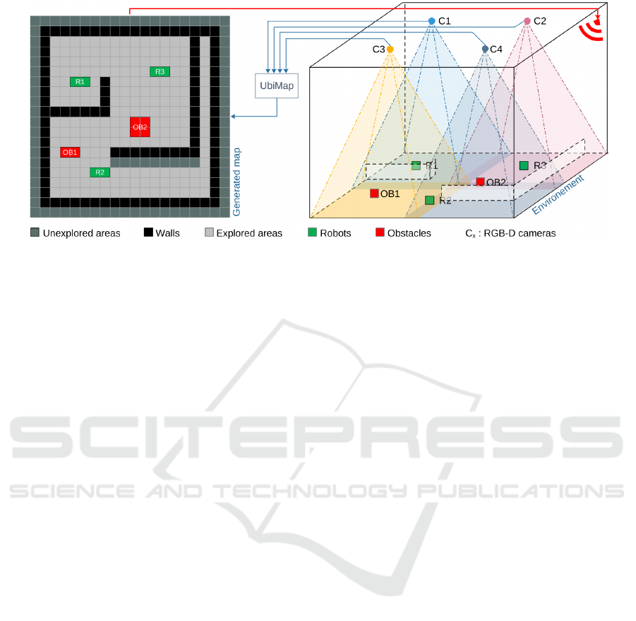
Figure 1: Real-time mapping system of an indoor environment with multiple robots (R1, R2, R3) and obstacles (OB1, OB2).
On the right: a 3D representation of the RGB-D sensor network (C1, C2, C3, C4) positioned to cover different areas. On the
left: a generated map displays the exploration status of the environment. Explored areas are shown in light gray, unexplored
areas in dark gray, and walls are represented in black. Robots are marked in green (R1, R2, R3) and obstacles in red (OB1,
OB2). The map produced is then transmitted to the various robots via a wireless link.
2 LIMITATIONS OF SLAM IN
INDOOR ENVIRONMENTS
SLAM (Simultaneous Localization and Mapping)
(Taheri and Xia, 2021) is a fundamental method in
mobile robotics and perception that aims to address
the challenge of localization and mapping in unknown
environments. The core challenge of SLAM lies in
the circular dependency between accurate localization
and the construction of a coherent map: a robot needs
to know its relative pose (position and orientation) to
generate an accurate map, yet conversely, it requires a
map to accurately determine its pose.
In the literature, two primary approaches emerge
to address the SLAM problem. The first, based on
the robot’s own movements, is commonly known as
Odometry-SLAM (Yang et al., 2020). This method
relies on the robot’s model to estimate its current po-
sition x
t
relative to its initial pose x
0
, using sensors
such as odometers and accelerometers. However, a
major drawback of this approach is drift, which af-
fects the accuracy of measurements over time due to
the inherent limitations of the sensors and the slip oc-
curring between the robot’s wheels and the ground.
The second main category, known as Visual
SLAM (Kazerouni et al., 2022), uses external ele-
ments with sensors like monocular or stereo cameras,
LiDAR, or RGB-D cameras. This method relies on
environmental features used as landmarks to estimate
the robot’s pose. One of the main challenges of this
technique lies in the ability to identify the same land-
marks between two successive moments, x
t−1
and x
t
,
to ensure consistent tracking of the position, espe-
cially in dynamic environments (Nielsen and Hen-
deby, 2022). Although Visual SLAM is also prone to
drift, this can potentially be corrected by detecting the
initial point x
0
at the end of the trajectory, this chal-
lenge is known as the “loop closure problem” (Cout-
sias et al., 2004; Chen et al., 2021).
Finally, a third category of SLAM is less-
developed and is based on using acoustic elements
in the environment. This technique, called Acoustic
SLAM, leverages an array of microphones to achieve
localization based on the acoustic properties of the
environment (Hu et al., 2023). This approach is par-
ticularly emerging in underwater robotics and is less
commonly applied in indoor environments.
Technically, SLAM combines the two mentioned
above techniques, often referred to as visual odom-
etry (Kazerouni et al., 2022). It uses onboard sen-
sors, such as LiDAR, RGB-D cameras, and inertial
measurement units (IMUs), which provide sensory in-
formation about the environment. Estimation algo-
rithms (Strasdat et al., 2012), such as the Extended
Kalman Filter (EKF-SLAM), particle filters (Fast-
SLAM) (Montemerlo, 2002), and graph-based opti-
mization methods (Graph-SLAM) (Thrun and Mon-
temerlo, 2006), are used to solve nonlinear state equa-
tions and optimize both the robot’s pose and the map
of surrounding features. These methods enable error
minimization and the handling of sensor uncertainties
by Leveraging-Bayesian probability techniques and
recursive filtering (Nadiga et al., 2019).
The mathematical formulation of SLAM is based
on a probabilistic model, where the objective is to
ICAART 2025 - 17th International Conference on Agents and Artificial Intelligence
538

maximize the joint probability of the robot’s state
and the map based on observations and movements
(Kudriashov et al., 2020). This problem is gener-
ally framed as a sequential Bayesian filtering prob-
lem. The goal is to jointly estimate the robot’s po-
sition x
t
and the environment map m using observa-
tions z
t
and motion commands u
t
. This process can
be described in three steps: (1) prediction, (2) update,
and (3) joint estimation (Bayesian filtering) (Do et al.,
2016).
a. Position Prediction. The robot estimates its cur-
rent position x
t
based on its previous position x
t−1
and
the applied motion command u
t
:
p(x
t
|x
t−1
, u
t
) (1)
b. Observation Update. The observations z
t
are
used to adjust the robot’s estimated position and up-
date the map m by comparing the current observations
with the existing map:
p(z
t
|x
t
, m) (2)
The estimation can be performed in several differ-
ent ways, including:
c.1 Bayesian Filtering. The position and map are
re-estimated by combining predictions with new ob-
servations to obtain a more accurate estimate:
p(x
t
, m|z
1:t
, u
1:t
) = η p(z
t
|x
t
, m)
Z
p(x
t
|x
t−1
, u
t
)p(x
t−1
, m|z
1:t−1
, u
1:t−1
)dx
t−1
(3)
where η is a normalization factor.
The pose and map estimation is sequential, car-
ried out by incorporating new data progressively to
build a map and locate the robot within that map. An
erroneous estimate at t
−n
will accumulate across all
estimates required for each p
t
−
n
to p
t
.
c.2 Extended Kalman Filter Approach (EKF-
SLAM): When the motion and observation models
are approximately linear around an estimate, the Ex-
tended Kalman Filter (EKF-SLAM) can be used to
solve the problem (Bailey et al., 2006). This approach
approximates the models by linearizing around the
current estimate, allowing the position and map esti-
mation to be updated using Gaussian distributions in
two steps:
State Prediction.
x
t
= f (x
t−1
, u
t
) + w
t
(4)
Where w
t
∼ N (0, Q) represents model noise.
Observation.
z
t
= h(x
t
, m) + v
t
(5)
Where v
t
∼ N (0, R) represents observation noise.
These equations and distributions allow for calcu-
lating and maintaining a real-time estimate of both
pose and the map. SLAM thus becomes a recursive
estimation of the map and localization based on sen-
sor data and movement commands within a Bayesian
framework. There are numerous variants that attempt
to optimize this technique (Zhang et al., 2018).
2.1 Review of SLAM Methods
In the following section, we will explore some
of the most advanced SLAM methods, including
MonoSLAM, PTAM, and ORB-SLAM (Taketomi
et al., 2017). These approaches have played a fun-
damental role in the development of simultaneous lo-
calization and mapping, each offering its own advan-
tages and disadvantages. We will examine them in the
chronological order of their emergence.
2.1.1 MonoSLAM
MonoSLAM is one of the first implementations of
monocular SLAM (Davison, 2003; Davison et al.,
2007). Based on an Extended Kalman Filter (EKF),
this method enables the simultaneous estimation of
camera motion and 3D structure in an unknown envi-
ronment. MonoSLAM uses feature points in the im-
age for tracking, with the Kalman filter maintaining
a continuous state estimation. However, the method
is limited by its computational cost, which increases
proportionally with the size of the environment, mak-
ing real-time application in large environments chal-
lenging.
2.1.2 Parallel Tracking and Mapping
Parallel Tracking and Mapping (PTAM) was de-
veloped to overcome some of the limitations of
MonoSLAM by separating camera tracking and map-
ping into two parallel processes. Introduced by (Klein
and Murray, 2007), PTAM uses Bundle Adjustment
(BA) optimization to enhance map accuracy. The
method relies on keyframes to reconstruct the map,
and localization algorithms allow the recovery of the
camera’s position if it is lost. Thanks to its multi-
threaded approach, PTAM can handle thousands of
feature points, making it a robust solution for con-
fined indoor environments with limited size.
Towards Ubiquitous Mapping and Localization for Dynamic Indoor Environments
539

2.1.3 ORB-SLAM
Developed in 2015 (Mur-Artal et al., 2015), ORB-
SLAM represents a significant advancement by utiliz-
ing robust ORB (Oriented FAST and Rotated BRIEF)
features. This open-source and modular method in-
cludes modules for relocalization and loop closure,
making the system highly stable and accurate even
in unstructured environments. ORB-SLAM employs
pose graph optimization and global bundle adjustment
to maintain the geometric consistency of the map. It
supports monocular, stereo, and RGB-D SLAM, mak-
ing it one of the most comprehensive and versatile
SLAM methods. ORB-SLAM ensures precise cam-
era tracking and high-quality mapping, and has been
widely adopted in robotics and augmented reality ap-
plications due to its open-source nature and ability to
run in real-time with limited computational resources.
In 2016, ORB-SLAM2 was developed (Mur-Artal
and Tard
´
os, 2017) as an extension of ORB-SLAM,
supporting not only monocular cameras but also
stereo and RGB-D cameras. This version enhances
the system’s robustness by leveraging the depth in-
formation provided by stereo or RGB-D sensors, al-
lowing it to resolve the scale ambiguities inherent
in monocular configurations. ORB-SLAM2 also in-
tegrates improvements in loop detection and global
map optimization, making the system better suited for
dynamic and large-scale environments. By incorpo-
rating depth information, ORB-SLAM2 can provide
more accurate mapping and improve stability during
rapid camera movements.
The latest version, ORB-SLAM3, released in
2021 (Campos et al., 2021), is the most advanced it-
eration of the ORB-SLAM series, adding support for
visual-inertial fusion. This version allows the sys-
tem to utilize inertial sensor data (IMU) to improve
tracking accuracy in scenarios involving rapid move-
ments or challenging environments for visual feature
detection. ORB-SLAM3 supports monocular, stereo,
RGB-D, and visual-inertial configurations, making it
highly versatile. With enhanced modules for initial-
ization and optimization, as well as for loop detection
in complex environments, ORB-SLAM3 is one of the
most comprehensive SLAM systems, suitable for ad-
vanced robotics applications.
ORB-SLAM, with its successive evolutions, of-
fers a robust and versatile suite of tools capable of
adapting to various types of sensors and applications,
establishing itself as a standard in visual SLAM. Each
of these methods has made a significant contribution
to the field of visual SLAM, addressing diverse needs
and meeting the challenges of localization and map-
ping in complex environments.
2.2 Limitations of SLAM Methods
Traditional SLAM methods (Stachniss et al., 2016),
although well-established, reveal significant limita-
tions in dynamic (Xing et al., 2022) and unstruc-
tured environments where frequent human-robot in-
teractions occur (Soares et al., 2021). In SLAM, the
sensors (often LiDAR, RGB-D cameras, and IMUs)
are mounted directly on the robots, meaning that the
map and localization are incrementally built as the
robot explores the environment. This makes SLAM
highly dependent on the detection capabilities of each
mobile unit and vulnerable to rapid environmental
changes, such as obstacles movements or the presence
of humans in the mapped space. These disruptions
can introduce inconsistencies and errors in the gener-
ated maps, making position updates less reliable. We
have analyzed and identified a major issues inherent
to SLAM in dynamic environments:
Error Accumulation and Drift. Over time, localiza-
tion errors accumulate in traditional SLAM systems,
causing a phenomenon known as ”drift”, which dis-
torts the map and compromises positional accuracy.
This issue is especially significant in large environ-
ments or those lacking fixed reference points, where
drift becomes a major problem that requires complex
and often computationally expensive correction tech-
niques.
Dependence on Onboard Sensors. As previously
mentioned, SLAM methods rely on sensors mounted
directly on the robot. This dependence means that
mapping and localization are tightly linked to the
perception and detection capabilities of the moving
robot. Consequently, if a robot loses visual con-
tact or encounters obstacles outside of its detection
range, the map’s accuracy may degrade. While ad-
vanced methods like ORB-SLAM can correct map
drift through loop closure by detecting the initial point
x
0
at the end of a path, their effectiveness is largely
confined to relatively static environments. In set-
tings where obstacles frequently shift positions—such
as those with moving humans or other robots—these
methods often face inconsistencies in obstacle lo-
calization, as real-time updates become increasingly
challenging in a continuously changing space.
Scalability Issues. As the environment to be mapped
grows, computational and memory demands increase,
making it challenging to extend traditional SLAM to
large or complex environments without performance
degradation. Systems must maintain an increasingly
large and detailed map, which can slow down real-
time processing.
Perception Limits and Computational Complexity.
Due to the nonlinear complexity of simultaneously
ICAART 2025 - 17th International Conference on Agents and Artificial Intelligence
540

estimating pose and mapping, SLAM systems re-
quire robust and computationally intensive algorithms
(Samsuri et al., 2015), which can make challenges
for implementation on robots with limited compu-
tational capabilities. Algorithms like the Extended
Kalman Filter (EKF) or particle-based techniques are
resource-demanding, limiting their real-time applica-
tion on low-cost robots or those with minimal pro-
cessing power.
Lack of Coordination in Multi-Robot Systems.
In applications where multiple robots work together
(Chen et al., 2023), each robot often handles its own
localization and mapping, which can lead to discrep-
ancies between the maps generated by each unit. Tra-
ditional SLAM approaches lack built-in mechanisms
for map fusion or synchronization of localization in-
formation across multiple robots, limiting their col-
laborative capability.
The primary difference with a ubiquitous ap-
proach, which we will now refer to as UbiSLAM,
lies in the fact that the sensors are fixed and provide
continuous coverage of the entire operational area.
Rather than relying on a mobile unit to build and
update the map, UbiSLAM leverages a network of
RGB-D cameras strategically placed in the environ-
ment, creating a real-time map accessible to all mo-
bile units. This approach overcomes the fragmented
and dynamic nature of traditional SLAM mapping.
Indeed, the fixed sensor network maintains a compre-
hensive and up-to-date view of the space, making the
map less susceptible to sudden movements and con-
figuration changes.
UbiSLAM also offers advantages in computational
cost and reliability. By centralizing mapping and re-
ducing the need for each robot to perform simulta-
neous localization and mapping, the system allows
for the use of less powerful robots while still ensur-
ing accurate mapping. Furthermore, the integration of
human posture detection within UbiSLAM enhances
safety and interaction in applications where humans
and robots coexist, in contrast to traditional SLAM
systems that do not naturally integrate this type of
tracking.
3 UBIQUITOUS MAPPING
APPROACH
The proposed mapping approach, UbiSLAM, utilizes
a network of fixed sensors – primarily RGB-D cam-
eras – strategically positioned throughout the environ-
ment to enable robust and precise mapping indepen-
dent of the sensors onboard the robots. This paradigm
aims to overcome the limitations of traditional SLAM
systems by eliminating the cumulative error sources
inherent to onboard sensors and enhancing system re-
silience to rapid environmental changes.
RGB-D cameras are installed in optimized loca-
tions to ensure complete coverage of the workspace.
These cameras provide a stable data source, allowing
precise tracking of the positions of robots and obsta-
cles within the environment. The cameras calculated
strategic distributed and oriented positions are done
in order to minimize blind spots and optimally max-
imize observational redundancy, enabling robust and
continuous monitoring across the environment. This
configuration not only mitigates the risk of coverage
gaps due to possible partial sensor network failures,
but also addresses potential latency issues by allow-
ing overlapping fields of view. In cases of network
delay or sensor lag, the overlapping coverage ensures
that critical areas are still monitored in near real-time,
as adjacent cameras can supplement delayed or miss-
ing data.
Data collected by each camera is centralized and
fused in real time, enabling the production of a global
map of the environment with enhanced accuracy.
This approach can use multi-sensor fusion techniques.
The generated map is continuously updated to reflect
changes in the environment (such as objects move-
ments or the appearance of new obstacles) and is
made accessible to all robots operating within this
space.
Each robot uses the centralized map provided by
the system, rather than relying solely on its onboard
sensors for localization. By integrating this infor-
mation, robots benefit from continuous localization
correction, reducing cumulative errors and enhancing
movement accuracy. This shared map also enables
better coordination among robots, promoting multi-
robot collaboration without collision risks and facili-
tating information sharing in shared environments.
By offloading the mapping and localization pro-
cessing, UbiSLAM significantly reduces the compu-
tational load and energy consumption of the robots.
With centralized data processing, robots can oper-
ate with lighter, energy-efficient hardware, improv-
ing their autonomy and adaptability in environments
where extended operational duration is essential.
The use of fixed RGB-D cameras ensures greater
resilience to frequent disturbances and dynamic
changes in the environment. Robots can adapt to
new spatial configurations in real time without los-
ing precision or efficiency. Furthermore, the redun-
dancy of observations from fixed cameras enhances
the system’s robustness against temporary occlusions
and rapid environmental changes.
In conclusion, the ubiquitous mapping approach
Towards Ubiquitous Mapping and Localization for Dynamic Indoor Environments
541

proposed by UbiSLAM represents a significant ad-
vancement over traditional SLAM methods, provid-
ing a collaborative, distributed, and highly resilient
mapping solution. UbiSLAM will bring notable im-
provements in localization accuracy and map quality,
paving the way for new applications in collaborative
robotics, service robotics, and indoor industrial au-
tomation.
3.1 Challenges Inherent to UbiSLAM
The proposed solution raises several issues that must
be addressed to ensure a high-performance solution.
A few key challenges have been identified which are:
a. Optimization of Camera Placement. The op-
timal positioning of RGB-D cameras is crucial to
achieve maximum coverage of the space while min-
imizing uncovered areas and excessive redundancies.
Camera placement must be calculated to cover strate-
gic zones where robots and humans frequently inter-
act. This requires determining each camera’s viewing
angle, range, and height, taking into account spatial
constraints and potential obstacles that might block
the field of view. A rectangular tiling optimization ap-
proach can be employed to ensure complete coverage
of the space while minimizing the number of cameras
required.
b. Automatic Camera Calibration. Initial calibra-
tion and ongoing maintenance of fixed cameras repre-
sent a major challenge, as each camera must be pre-
cisely aligned with the global coordinate system to
ensure consistent mapping. This includes adjusting
orientations, correcting optical distortions
1
, and de-
termining the exact position of each camera within the
environment. Automatic calibration would simplify
the initial deployment of the sensor network and fa-
cilitate reconfiguration if the camera layout changes.
c. Real-Time Communication Protocol. A ro-
bust, low-latency communication system is essential
for enabling the instantaneous sharing of localization
and mapping data between fixed sensors and mobile
robots. The protocol must ensure data synchroniza-
tion to provide a consistent view of the environment at
all times. In environments with potential blind spots,
the global map can be supplemented with data from
robot sensors and then merged. Data fusion from
robot sensors requires a bidirectional communication
protocol.
1
The issue of optical distortions is not addressed further
in this article.
d. Merging Maps Generated by Robots. In col-
laborative environments, each robot may generate its
own local map based on information collected by its
onboard sensors (Liu and Zhu, 2023). Merging these
local maps with the global map (Cristofalo et al.,
2020), created by the network of fixed cameras, is
essential for ensuring consistency in navigation and
localization across robots. This fusion requires so-
phisticated data processing algorithms capable of in-
tegrating maps while correcting potential errors from
inconsistencies or redundancies between the local and
global maps. A consensus system is necessary for this
purpose (Gao et al., 2020). Additionally, this fusion
process must be adaptable to frequent environmental
changes, such as obstacles movement or spatial re-
configurations.
In summary, the challenges associated with imple-
menting UbiSLAM highlight the complexity of a col-
laborative mapping and localization system in a dy-
namic environment. Optimizing camera placement
and calibration, the need for a real-time communi-
cation protocol, and the merging of local and global
maps are all issues that require robust solutions to
ensure optimal accuracy and adaptability to environ-
mental changes. In the following sections, we will
outline potential solutions for the first two challenges.
4 CAMERA PLACEMENT
OPTIMIZATION
To optimize the placement of RGB-D cameras, we
propose using a rectangular tiling technique (Al-
lauzen and Durand, 1997). In this approach, the space
is divided into regular square cells, each representing
a unit of the area to be covered. For such tiling, each
camera is positioned so that its field of view covers a
group of square cells, thereby maximizing coverage
with minimal overlap. We consider the environment
as a discrete space divided into a regular grid of cells
S = {s
1
, s
2
, . . . , s
n
} where each s
j
∈ S is a region or
cell within the space that needs coverage, with each
cell representing a potential coverage point for a sen-
sor.
The RGB-D cameras placed in the environment
have a limited field of view, defined by a view-
ing angle and maximum range, and we assume that
all cameras have the same characteristics. Let C =
{c
1
, c
2
, ..., c
n
} represent the set of cameras, where
each camera c
i
has a field of view FOV
i
determined
by its coverage angle and maximum range.
We define a coverage function f : C → 2
s
that as-
sociates each camera position c
i
with the set of cells
s
j
covered by c
i
.
ICAART 2025 - 17th International Conference on Agents and Artificial Intelligence
542

f (c
i
) = {s
j
: the sensor placed at c
i
can cover s
j
}
The coverage range is defined by the camera’s
field of view and maximum distance. The total cover-
age of the environment by a set of cameras P is there-
fore:
Total coverage(P) =
[
c
i
∈P
f (c
i
)
The objective is to optimize the subset P ⊆ C to
maximize the total coverage of S, minimizing uncov-
ered areas, increasing redundancy in strategic areas
(such as zones where robots frequently interact), and
minimizing the number of cameras for cost and com-
plexity reasons. This can be formulated as an integer
linear programming problem (Wolsey, 2020).
To optimize the placement of RGB-D cameras
while considering height above the ground, we define
the following parameters based on the 3D projections
of the field of view onto the ground plane.
a. Camera Height. Let h
i
represent the height of
camera c
i
above the ground. This height influences
both the range and shape of the covered area on the
ground based on projection geometry. It is also im-
portant to note that the height at which the camera is
positioned can affect data quality (Rodriguez, 2021).
b. Ground Projection of Field of View. Consider
the field of view of a camera defined by a vertical cov-
erage angle β and a horizontal coverage angle α. The
maximum projected range on the ground, d
i
, for cam-
era c
i
is given by:
d
i
= h
i
· tan
β
2
Where h
i
is the height of the camera. This allows us
to define the rectangular coverage projected onto the
ground, with a maximum depth d
i
and a width w
i
=
2 · h
i
· tan
α
2
, where α is the horizontal field of view
angle.
c. Ground Coverage Area. The projection of each
camera c
i
’s, coverage area, positioned at (x
i
, y
i
) on
the ground plane, takes the form of a rectangle with
dimensions w
i
× d
i
, oriented along the camera’s di-
rection. Thus, a point (x, y) is covered by c
i
if, after
transformation by the camera’s orientation angle θ, it
satisfies :
x
i
−
w
i
2
≤ x ≤ x
i
+
w
i
2
And
y
i
≤ y ≤ y
i
+ d
i
.
d. Coverage Function. Let S = {s
1
, s
2
, . . . , s
n
} be
the set of ground cells to cover, where each cell s
j
∈ S
represents a discrete region of the space. The to-
tal coverage function, which we aim to maximize, is
given by:
f (C, S) =
∑
s
j
∈S
min
1,
∑
c
i
∈C
proj cov
c
i
(s
j
)
!
Where proj cov
c
i
(s
j
) is an indicator function equal to
1 if cell s
j
falls within the ground projection of the
field of view of c
i
, and 0 otherwise.
e. Overlap Optimization. To minimize coverage
redundancies while ensuring complete coverage of S,
we introduce an overlap constraint:
m ≤
∑
c
i
∈C
proj cov
c
i
(s
j
) ≤ k
For each cell s
j
∈ S, where k is the maximum
allowable overlap threshold and m
´
etant le seuil de
chevauchement minimal. is the minimum overlap
threshold. It is important to maintain a non-zero space
between m and k to ensure an overlap zone where
landmarks can be placed for sensor calibration. The
following section addresses this issue in more details.
This modeling provides a rigorous mathematical
framework for an optimization problem that combines
camera height, coverage angles, and ground projec-
tions to maximize the coverage efficiency of the space
S. It is important to note that S can be limited strictly
to critical areas to reduce the number of cameras re-
quired, leaving shadowed zones in areas deemed non-
critical. This perspective is not covered by the tech-
nique described above.
5 CAMERAS ON THE SAME
PLANE
Determining the position of each camera relative to
a global reference R
0
is crucial for calibrating mul-
tiple RGB-D cameras, enabling consistent object re-
construction and precise data fusion to generate a de-
tailed map. In the proposed system, multiple cameras
are positioned to cover the space with a slight over-
lap m between adjacent fields of view. This small
overlap is utilized to align coordinate systems using
landmarks visible to adjacent sensors. In each over-
lap zone, easily detectable landmarks are placed, visi-
ble in the RGB-D data of both cameras involved, thus
serving as common references for aligning their lo-
cal coordinate systems. These landmarks can take the
Towards Ubiquitous Mapping and Localization for Dynamic Indoor Environments
543

form of visual markers integrated into the environ-
ment, such as color markers, or distinct-shaped ob-
jects that are easily identifiable in depth data.
For each pair of cameras sharing an overlap zone,
the coordinates of the landmarks are recorded in each
camera’s local coordinate system. The RGB-D cam-
era captures both color and depth data, thereby pre-
cisely locating the landmarks in 3D within the lo-
cal spaces of the cameras. These landmark coordi-
nates are then used to estimate the geometric trans-
formation (rotation and translation) between the co-
ordinate systems of adjacent cameras, applying algo-
rithms such as ICP (Iterative Closest Point) (Zhang
et al., 2021) or correspondence-based methods. These
techniques minimize the error between correspond-
ing landmarks, providing a reliable estimation of the
transformation.
Once transformations are calculated for each cam-
era pair, they are integrated into a transformation
graph (Sooriyaarachchi and Gamage, 2022), where
each node represents a camera, and each edge repre-
sents the estimated transformation between two ad-
jacent cameras. Starting from a global reference
frame R
0
, the transformations are propagated through
the graph to align each camera to this global refer-
ence. To minimize accumulated errors during propa-
gation, a global optimization is applied to the cam-
eras’ positions and orientations, employing SLAM
techniques to reduce calibration errors. This opti-
mization enhances accuracy by adjusting transforma-
tions to maintain the overall coherence of the system.
C
1
C
2
z
1
z
2
p
1
p
2
p
3
Field of View C
1
Field of View C
2
Overlap Zone
To calibrate RGB-D cameras in a three-
dimensional space using overlap zones, we pro-
pose a system that uses ICP (Wang and Zhao, 2017;
Chetverikov et al., 2002) to estimate rigid transforma-
tions between cameras sharing common landmarks in
the overlap zones. The ICP algorithm is particularly
suited to this situation, as it minimizes the error
between two point sets by adjusting the rotation and
translation of one set relative to the other. First,
rigid transformations T
i j
are defined for each pair of
cameras that share an overlap zone where landmarks
are identified. Then, ICP is applied to estimate these
transformations by minimizing the distances between
corresponding landmarks. A transformation graph
is subsequently constructed to link the cameras,
allowing for transformation propagation within a
global reference frame R
0
, thereby expressing each
camera within this global frame. Finally, a global
optimization is performed to reduce accumulated
errors and ensure precise calibration across the entire
system.
Rigid Transformation with ICP. For each pair of
cameras with an overlap zone, we define a rigid trans-
formation T
i j
that aligns the coordinate system of
camera i with that of camera j. This transformation
T
i j
includes a rotation matrix R
i j
and a translation vec-
tor t
i j
:
T
i j
=
R
i j
t
i j
0 1
Where R
i j
∈ R
3×3
and t
i j
∈ R
3
.
Acquisition of Landmark Points in Overlap Zones:
For each pair of cameras sharing an overlap zone,
we obtain two sets of landmark points: P
i
=
{p
1
i
, p
2
i
, . . . , p
n
i
} in the coordinate system of camera
i and P
j
= {p
1
j
, p
2
j
, . . . , p
n
j
} in the coordinate system
of camera j. These landmark points serve as inputs
for the ICP algorithm.
Application of the ICP Algorithm. The ICP algo-
rithm is applied to align points P
i
from camera i to
points P
j
from camera j, minimizing the distance be-
tween each pair of corresponding points. ICP per-
forms the following steps: (1)Matching Step. For
each point in P
i
, the closest point in P
j
is identified.
(2)Optimization Step. The transformation T
i j
(com-
prising R
i j
and t
i j
) is calculated to minimize the sum
of squared distances between corresponding points.
This optimization is solved using the least squares
method. These steps are repeated until convergence
is reached, meaning that the average difference be-
tween the distances of corresponding points falls be-
low a specified threshold s.
Construction du Graphe de Transformations.
Once the transformations T
i j
are calculated for each
camera pair, the cameras are modeled as a graph
where each camera is a node, and each transforma-
tion T
i j
represents an edge connecting two adjacent
cameras.
Propagation of Transformations to the Global Ref-
erence Frame R
0
. To express each camera in the
global reference frame R
0
, we multiply transforma-
tions along the paths in the graph. For example, if
ICAART 2025 - 17th International Conference on Agents and Artificial Intelligence
544

camera k is connected to R
0
via cameras i and j, then
the global transformation T
0k
is given by:
T
0k
= T
0i
T
i j
T
jk
Global Transformation Optimization. To mini-
mize accumulation errors in the graph, a global op-
timization is applied by minimizing a cost function C,
which represents the sum of matching errors for each
camera pair. The cost function is defined by:
C =
∑
(i, j)
∑
k
∥T
i j
p
k
i
− p
k
j
∥
2
Where p
k
i
and p
k
j
are the coordinates of the k-th
landmark in the coordinate systems of cameras i and
j. This optimization adjusts the transformations T
i j
to minimize the total calibration error in the system.
Optimization methods such as Levenberg-Marquardt
(LM algorithm) (Ranganathan, 2004) will be used to
refine the transformations and minimize inconsisten-
cies.
In this section, we proposed an ICP-based ap-
proach that enables precise calibration of RGB-D
cameras by using overlap zones to align each camera
within a global reference frame R
0
. This alignment
allows all entities in the environment to orient them-
selves within a common reference frame, thus simpli-
fying localization challenges.
6 LOCALIZATION
To reliably locate the robots, each robot is equipped
with a unique visual identifier, easily detectable by
RGB-D cameras positioned throughout the space.
This identifier, placed on top of each robot, provides
a precise landmark that enables the system to calcu-
late the robot’s exact position in the global reference
frame R
0
. The cameras continuously capture the iden-
tifier code, and the system deduces the robot’s spatial
coordinates based on the relative position of the code
with respect to the cameras.
Additionally, for obstacles localization and human
detection, a technology such as the YOLO object de-
tection model (Diwan et al., 2023) can be integrated
into the system. This allows real-time object detec-
tion and identification of moving objects, including
people, and situates them in space relative to R
0
. The
model proposed here functions effectively in dynamic
environments, where it can identify unexpected obsta-
cles or humans entering the workspace. A fixed local-
ization method utilizing a large network of RGB-D
cameras offers several advantages in dynamic envi-
ronments such as dense, collaborative manufacturing
setups. By deploying these cameras throughout the
space, UbiSLAM enables precise tracking of robots,
static objects, and human movement. This approach
ensures accurate and continuous localization without
relying on onboard sensors, offering enhanced robust-
ness in complex environments where both environ-
mental dynamics and operational efficiency are cru-
cial.
One other key benefit of this fixed localization
method is its ability to track essential specialized
items stored in less frequently used areas of the manu-
facturing process. In large, busy manufacturing ware-
houses, locating goods or assets that are not in regu-
lar use can be a significant challenge, often resulting
in inefficiencies and delays. The comprehensive data
provided by the RGB-D camera network allows for
consistent monitoring of these assets, ensuring they
are not only tracked in real-time but also stored and
retrieved efficiently when needed. By creating a digi-
tal map of the environment that continuously updates
and monitors key items, the system reduces the risk
of misplaced or under-utilized resources.
Additionally, the ability to store and access his-
torical data on asset location is particularly valuable
for optimizing workflows and inventory management.
Over time, this data can be leveraged to predict pat-
terns, improve operational strategies, and streamline
storage practices. While this approach still faces
challenges in large-scale applications, such as deal-
ing with sensor network failures or latency issues,
the potential of UbiSLAM to enhance the visibility
and traceability of goods and assets in manufactur-
ing environments is promising. Future exploration of
UbiSLAM’s application in these contexts could fur-
ther validate its effectiveness in improving inventory
tracking and asset management, ultimately benefiting
large-scale, collaborative manufacturing systems.
7 DISCUSSION
We discussed the advantages of having a fixed map-
ping and localization system. However, this system is
subject to certain limitations, notably areas not cov-
ered by the camera network, commonly called blind
spots. To address these, data from the robots must be
integrated, adding a layer of complexity to interoper-
ability between UbiSLAM and the robots.
The map is generated in real time and contin-
uously updated, integrating environmental changes
such as obstacles movements and the presence of peo-
ple. This map is then shared with the robots navi-
gating within the space, providing them with an up-
to-date global view of the environment. Robots can
Towards Ubiquitous Mapping and Localization for Dynamic Indoor Environments
545

thereby access location information for obstacles and
other agents, enhancing navigation and reducing col-
lision risks. Through this centralized mapping ap-
proach, the map generated by UbiSLAM is not only
precise but also adaptable in real time to environ-
mental dynamics, facilitating collaboration between
robots and humans in shared spaces.
The UbiSLAM approach represents significant ad-
vances in mapping and localization for dynamic in-
door environments, particularly where human-robot
interactions are frequent and unpredictable. In con-
trast to traditional SLAM methods, UbiSLAM em-
ploys a network of fixed sensors that provides real-
time, accurate, and comprehensive mapping of the
environment, thereby reducing the cumulative local-
ization errors typical of systems based on onboard
sensors. Strategically placed RGB-D cameras enable
continuous spatial modeling that is less affected by
rapid environmental changes. This architecture re-
duces the computational load on mobile robots by ex-
ternalizing mapping, leading to better energy manage-
ment and allowing simpler robotic units to operate re-
liably. Moreover, the considerable reduction in RGB-
D camera costs makes this solution easily applicable
in small to medium-sized indoor environments. The
price of a 3D LiDAR mounted on a robot can be up to
20 times that of an RGB-D sensor.
The mathematical methods used in UbiSLAM,
such as multi-sensor data fusion, can be extended with
probabilistic models like Bayesian filtering and the
Extended Kalman Filter (EKF), to handle uncertain-
ties associated with sensor measurements.
However, challenges remain, especially in achiev-
ing complete environmental coverage. Blind spots, or
areas without coverage, can lead to localization loss
for robots and require rigorous optimization of sen-
sor placement. Modeling this aspect through discrete
coverage techniques, where each camera covers spa-
tial units according to a coverage function f (C), could
maximize coverage while minimizing excessive over-
lap, thus reducing deployment costs and complexity.
The resulting combinatorial optimization problem is
often addressed using heuristics such as sensor place-
ment optimization algorithms, which aim to find an
optimal distribution of cameras in the space but typi-
cally yield approximate solutions.
The integration of real-time detection models,
such as YOLO for identifying obstacles and people,
offers a valuable complement to identifier code-based
robot localization. YOLO enables rapid and reliable
recognition of moving elements, making UbiSLAM
suitable for detecting and tracking moving objects
without adding additional sensors to the robots. This
framework presents promising prospects for collabo-
rative multi-robot environments, necessitating further
research to efficiently coordinate multiple units and
improve methods for merging local and global maps.
Future developments in UbiSLAM could focus on net-
work resource management to accelerate data flow
and apply advanced data fusion techniques to further
enhance the accuracy and robustness of the system in
constantly changing environmental conditions.
8 CONCLUSION
The proposed UbiSLAM approach marks a signifi-
cant advancement in mapping and localization for dy-
namic indoor environments. By integrating a network
of fixed sensors strategically placed throughout the
environment, this method overcomes the limitations
of traditional SLAM systems, which are often hin-
dered by obstacles changes and an inability to adapt
in real time. By providing comprehensive and con-
tinuous mapping, UbiSLAM enhances localization ac-
curacy and robot responsiveness, enabling improved
human-robot interaction in shared spaces. This ubiq-
uitous model reduces the computational load on mo-
bile units, ensuring increased robustness to rapid envi-
ronmental changes and optimizing the safety and flu-
idity of interactions.
However, UbiSLAM presents certain challenges
that merit further attention. Achieving complete spa-
tial coverage remains an issue, particularly in address-
ing blind spots (areas not covered by fixed sensors),
which require solutions to ensure coherent and con-
tinuous mapping. Integrating automatic calibration
techniques to optimize camera placement and orienta-
tion, along with improving communication protocols
for real-time information sharing, represent promis-
ing development avenues. Finally, extending this ap-
proach to more complex environments and evaluating
its effectiveness in collaborative multi-robot systems
will open up new possibilities for applications in ser-
vice and industrial robotics.
UbiSLAM offers a robust solution for ubiqui-
tous mapping and localization, enhancing navigation
and collaboration in complex indoor environments,
thereby laying the groundwork for a new generation
of intelligent systems for collaborative robotics.
REFERENCES
Allauzen, C. and Durand, B. (1997). Tiling problems. E.
Borger, E. Gradel, Y. Gurevich, The classical decision
problem. Springer-Verlag.
ICAART 2025 - 17th International Conference on Agents and Artificial Intelligence
546

Bailey, T., Nieto, J., Guivant, J., Stevens, M., and Nebot,
E. (2006). Consistency of the ekf-slam algorithm. In
2006 IEEE/RSJ International Conference on Intelli-
gent Robots and Systems, pages 3562–3568. IEEE.
Campos, C., Elvira, R., Rodr
´
ıguez, J. J. G., Montiel,
J. M., and Tard
´
os, J. D. (2021). Orb-slam3: An ac-
curate open-source library for visual, visual–inertial,
and multimap slam. IEEE Transactions on Robotics,
37(6):1874–1890.
Chen, W., Wang, X., Gao, S., Shang, G., Zhou, C., Li, Z.,
Xu, C., and Hu, K. (2023). Overview of multi-robot
collaborative slam from the perspective of data fusion.
Machines, 11(6):653.
Chen, X., L
¨
abe, T., Milioto, A., R
¨
ohling, T., Vysotska,
O., Haag, A., Behley, J., and Stachniss, C. (2021).
Overlapnet: Loop closing for lidar-based slam. arXiv
preprint arXiv:2105.11344.
Chetverikov, D., Svirko, D., Stepanov, D., and Krsek, P.
(2002). The trimmed iterative closest point algorithm.
In 2002 International Conference on Pattern Recogni-
tion, volume 3, pages 545–548. IEEE.
Coutsias, E. A., Seok, C., Jacobson, M. P., and Dill, K. A.
(2004). A kinematic view of loop closure. Journal of
computational chemistry, 25(4):510–528.
Cristofalo, E., Montijano, E., and Schwager, M. (2020).
Geod: Consensus-based geodesic distributed pose
graph optimization. arXiv preprint arXiv:2010.00156.
Davison (2003). Real-time simultaneous localisation and
mapping with a single camera. In Proceedings Ninth
IEEE International Conference on Computer Vision,
pages 1403–1410. IEEE.
Davison, A. J., Reid, I. D., Molton, N. D., and Stasse, O.
(2007). Monoslam: Real-time single camera slam.
IEEE transactions on pattern analysis and machine
intelligence, 29(6):1052–1067.
Diwan, T., Anirudh, G., and Tembhurne, J. V. (2023). Ob-
ject detection using yolo: Challenges, architectural
successors, datasets and applications. multimedia
Tools and Applications, 82(6):9243–9275.
Do, H. N., Jadaliha, M., Temel, M., and Choi, J. (2016).
Fully bayesian field slam using gaussian markov ran-
dom fields. Asian Journal of Control, 18(4):1175–
1188.
Gao, L., Battistelli, G., and Chisci, L. (2020). Random-
finite-set-based distributed multirobot slam. IEEE
Transactions on Robotics, 36(6):1758–1777.
Hu, D., Chen, Z., and Yin, F. (2023). Acoustic slam with
moving sound event based on auxiliary microphone
arrays. IEEE Transactions on Intelligent Transporta-
tion Systems.
Huang, S. and Dissanayake, G. (2016). A critique of current
developments in simultaneous localization and map-
ping. International Journal of Advanced Robotic Sys-
tems, 13(5):1729881416669482.
Kazerouni, I. A., Fitzgerald, L., Dooly, G., and Toal, D.
(2022). A survey of state-of-the-art on visual slam.
Expert Systems with Applications, 205:117734.
Klein, G. and Murray, D. (2007). Parallel tracking and
mapping for small ar workspaces. In 2007 6th IEEE
and ACM international symposium on mixed and aug-
mented reality, pages 225–234. IEEE.
Kudriashov, A., Buratowski, T., Giergiel, M., Małka, P.,
Kudriashov, A., Buratowski, T., Giergiel, M., and
Małka, P. (2020). Slam as probabilistic robotics
framework approach. SLAM Techniques Application
for Mobile Robot in Rough Terrain, pages 39–64.
Liu, S. and Zhu, J. (2023). Efficient map fusion for multiple
implicit slam agents. IEEE Transactions on Intelligent
Vehicles.
Montemerlo, M. (2002). Fastslam: A factored solution to
the simultaneous localization and mapping problem.
Proc. of AAAI02.
Mur-Artal, R., Montiel, J. M. M., and Tardos, J. D. (2015).
Orb-slam: a versatile and accurate monocular slam
system. IEEE transactions on robotics, 31(5):1147–
1163.
Mur-Artal, R. and Tard
´
os, J. D. (2017). Orb-slam2:
An open-source slam system for monocular, stereo,
and rgb-d cameras. IEEE transactions on robotics,
33(5):1255–1262.
Nadiga, B., Jiang, C., and Livescu, D. (2019). Leveraging
bayesian analysis to improve accuracy of approximate
models. Journal of Computational Physics, 394:280–
297.
Nielsen, K. and Hendeby, G. (2022). Multi-hypothesis slam
for non-static environments with reoccurring land-
marks. IEEE Transactions on Intelligent Vehicles,
8(4):3191–3203.
Ranganathan, A. (2004). The levenberg-marquardt algo-
rithm. Tutoral on LM algorithm, 11(1):101–110.
Rodriguez, J. S. (2021). A comparison of an rgb-d cam-
era’s performance and a stereocamera in relation to
object recognition and spatial position determination.
ELCVIA: Electronic Letters on Computer Vision and
Image Analysis, 20(1):0016–27.
Samsuri, S. B., Zamzuri, H., Rahman, M. A. A., Mazlan,
S. A., and Rahman, A. (2015). Computational cost
analysis of extended kalman filter in simultaneous lo-
calization and mapping (ekf-slam) problem for au-
tonomous vehicle. ARPN journal of engineering and
applied sciences, 10(17):153–158.
Saputra, M. R. U., Markham, A., and Trigoni, N. (2018).
Visual slam and structure from motion in dynamic
environments: A survey. ACM Computing Surveys
(CSUR), 51(2):1–36.
Soares, J. C. V., Gattass, M., and Meggiolaro, M. A. (2021).
Crowd-slam: visual slam towards crowded environ-
ments using object detection. Journal of Intelligent &
Robotic Systems, 102(2):50.
Sooriyaarachchi, S. and Gamage, C. (2022). Elastic
orb: Non-rigid transformation based slam. In 2022
Moratuwa Engineering Research Conference (MER-
Con), pages 1–6. IEEE.
Stachniss, C., Leonard, J. J., and Thrun, S. (2016). Simulta-
neous Localization and Mapping. In Siciliano, B. and
Khatib, O., editors, Springer Handbook of Robotics,
pages 1153–1176. Springer International Publishing,
Cham. Series Title: Springer Handbooks.
Towards Ubiquitous Mapping and Localization for Dynamic Indoor Environments
547

Strasdat, H., Montiel, J. M., and Davison, A. J. (2012). Vi-
sual slam: why filter? Image and Vision Computing,
30(2):65–77.
Taheri, H. and Xia, Z. C. (2021). Slam; definition and evo-
lution. Engineering Applications of Artificial Intelli-
gence, 97:104032.
Taketomi, T., Uchiyama, H., and Ikeda, S. (2017). Vi-
sual slam algorithms: A survey from 2010 to 2016.
IPSJ transactions on computer vision and applica-
tions, 9:1–11.
Thrun, S. and Montemerlo, M. (2006). The graph slam
algorithm with applications to large-scale mapping
of urban structures. The International Journal of
Robotics Research, 25(5-6):403–429.
Wang, F. and Zhao, Z. (2017). A survey of iterative clos-
est point algorithm. In 2017 Chinese Automation
Congress (CAC), pages 4395–4399. IEEE.
Wolsey, L. A. (2020). Integer programming. John Wiley &
Sons.
Xing, Z., Zhu, X., and Dong, D. (2022). De-slam: Slam
for highly dynamic environment. Journal of Field
Robotics, 39(5):528–542.
Yang, G., Wang, Y., Zhi, J., Liu, W., Shao, Y., and Peng,
P. (2020). A review of visual odometry in slam tech-
niques. In 2020 International Conference on Artifi-
cial Intelligence and Electromechanical Automation
(AIEA), pages 332–336. IEEE.
Zhang, J., Yao, Y., and Deng, B. (2021). Fast and robust
iterative closest point. IEEE Transactions on Pattern
Analysis and Machine Intelligence, 44(7):3450–3466.
Zhang, Y., Zhang, T., and Huang, S. (2018). Comparison
of ekf based slam and optimization based slam algo-
rithms. In 2018 13th IEEE Conference on Industrial
Electronics and Applications (ICIEA), pages 1308–
1313. IEEE.
ICAART 2025 - 17th International Conference on Agents and Artificial Intelligence
548
