
Validation of Requirements Models Using a Graph
Alexander Rauh
SOPHIST GmbH, Vordere Cramergasse 13, Nuremberg, Germany
Keywords: System Requirements, Model Validation, Requirements Quality, Quality Assurance.
Abstract: Validation of system requirements models is essential for success in system development. Especially in
regulated engineering domains like automotive or healthcare organisations have to prove their compliance
with regulations. One part of this compliance is the assurance of high-quality system requirements. Today’s
approaches often take high effort of requirements analysts or require more formal extensions of common
requirements documentation methods. This paper proposes a novel approach that validates requirements
models without any formal extensions like Object Constraint Language (OCL) by utilizing a graph structure
and graph transformations. In the first step, the requirements model is imported into a graph and is transformed
according to a common meta-model for requirements. The integration of a natural language processing (NLP)
pipeline provides possibilities to analyse the natural language parts during transformation. In the second step,
the structure of the graph is validated using pattern derived from rules for high quality system requirements.
A constructed example shows feasibility and helps to get early feedback to the graph-based concept.
1 INTRODUCTION
In the environment of systems engineering where
software, hardware, and mechanical engineering
must work hand in hand to fulfil functional safety and
cyber security, high-quality requirements are one
pillar to get an intradisciplinary understanding to the
system under development. Usually, these system
requirements serve as the foundation for various
engineering disciplines, including system
architectural design, system implementation, and
system testing. The quality of these requirements has
a far-reaching impact, influencing not only the
efficiency of these downstream processes but also the
system's ability to comply with critical regulations.
Depending on the system’s domain several
regulations like functional safety (IEC 61508)
(International Electrotechnical Commission, 2010) or
its specializations like functional safety for road
vehicles (ISO 26262) (International Organization for
Standardization, 2018) as well as regulations
regarding cyber security (IEC 62443) (International
Electrotechnical Commission, 2009) mandate
methods for ensuring requirement quality throughout
the system development. Organizations must prove
their compliance with these regulations to get the
permission to sell their products.
Process maturity models like Software Process
Improvement and Capability Determination (SPICE)
(International Electrotechnical Commission, 2015)
and their domain-specific derivatives like
Automotive SPICE (VDA Working Group 13, 2023)
also emphasize the importance of base practices for
ensuring the requirements quality. These practices,
which often centre around manual quality assurance
techniques like peer reviews, walkthroughs and
inspections aim to ensure a consistent, complete, and
reliable set of system requirements.
The IEEE 29148 (IEEE, 2018) defined a set of
quality characteristics for requirements, which
usually are referenced from the different regulations
to provide a common scale for quality assessments.
However, effectively evaluating these quality
characteristics within large and intricate requirements
models remains a significant challenge. Especially
consistency of system requirements across different
views is hard to achieve without any (tool) support to
requirements analysts.
The proposed approach provides a concept which
is particularly valuable when dealing with large
requirements models, where manual quality checks
become increasingly challenging and time-
consuming. Analysing every requirement for
adherence to quality characteristics can take a
significant amount of engineering effort, leading to
288
Rauh, A.
Validation of Requirements Models Using a Graph.
DOI: 10.5220/0013287100003896
In Proceedings of the 13th International Conference on Model-Based Software and Systems Engineering (MODELSWARD 2025), pages 288-296
ISBN: 978-989-758-729-0; ISSN: 2184-4348
Copyright © 2025 by Paper published under CC license (CC BY-NC-ND 4.0)

delays in the development process. Furthermore,
manual checks are susceptible to human error, such
as overlooking inconsistencies or missing
ambiguities due to fatigue or cognitive overload when
dealing with enormous amounts of data. Complex
relationships between requirements across different
views might be missed during a purely manual review
process. The proposed approach aims to empower
engineers by providing a method to efficiently assess
the requirements quality and to identify defects within
system requirements. One major advantage to
existing approaches is that requirements analysts do
not need to extend the requirements model with
formal aspects like Object Constraint Language
(Object Management Group, Inc., 2014) to enable
common model validation. Furthermore, the method
for capturing system requirements must not be
adjusted to the validation mechanism but mechanism
is adjusted to the method. The engineers use defined
algorithms and get feedback immediately if their
system requirements meet the specific quality
characteristics and get information about potential
defects within the requirements model.
Following this introduction related works is
discussed to explain limitations of existing
approaches. The third section introduces a
requirements integration concept and its major terms
which serves as the foundation for validating the
system requirements. The fourth section describes the
implementation of the requirements integration
concept using a graph-based approach. A constructed
example of a requirements model for a smartphone is
used to explain the implementation and to show
feasibility of the concept. The fifth section describes
different pattern types derived from the method for
capturing high-quality system requirements to
validate the graph of integrated requirements. As a
conclusion, the major benefits, current limitations,
and possibilities for further research are discussed.
2 RELATED WORKS
Effective requirements quality assessment is crucial
for successful system development. This section
delves into existing research.
(Al-Fedaghi, 2021) proposes an informal
validation of textual system requirements using
activity diagrams and Thinging Machine (TM) which
is the authors understanding on how to structure
things and processes within a system under
development. The concept requires to create activity
diagrams as part of the system design based on the
textual system requirements. From these activity
diagrams the requirements analysts create a TM and
check this TM against the system requirements in an
informal validation like a peer review. The proposed
approach is limited to activity diagrams which,
furthermore, are an extension of the previously
captured system requirements. Requirements analysts
must extend or adjust their method for capturing
system requirements to support the mentioned
concept. Furthermore, this informal validation is
prone to errors humans will make. Additionally, the
approach does not provide any quality characteristics
that should be validated.
(Torre, 2016) provides a concept to verify the
consistency of UML models by explaining
consistency rules in OCL. The UML model is
checked against these defined OCL constraints. The
mentioned approach is limited to consistency as
assessable quality characteristic and requires
extension of the UML model including the system
requirements by OCL which lead to adjustments of
the method for capturing system requirements.
Furthermore, analysis of natural language parts of the
model elements is limited.
Another similar approach leverages ontology
reasoning to identify inconsistencies in software
requirements (Kroha et al., 2009). The concept is split
into two steps. In the first step, the static parts and
constraints of a UML model are converted into an
ontology. After transformation, an ontology
reasoning engine is used to identify inconsistencies in
the requirements. In the second step, the requirements
ontology is compared to a separate domain-specific
ontology, which represents knowledge about the
respective domain of the software like finance or
healthcare. If a requirement contradicts to the
knowledge of the domain, the algorithm highlights
the conflict. The authors state that the approach
cannot manage the dynamic aspects like the model’s
behaviour of the software to be developed. Another
limitation is that only consistency of the requirements
specification will be analysed.
(Hausmann et al., 2002) is an article about
detecting conflicting functional requirements in a use
case-driven approach. It discusses the challenges of
finding these conflicts due to the informal nature of
requirements. The authors propose a formal
interpretation of use case models that allows for static
analysis to detect these conflicts. This analysis is
based on graph transformation theory. The benefits of
this approach are that it supports the requirements
engineers to identify conflicting requirements
without additional effort for formalisation because of
the automated graph transformation. The approach
described in this paper also proposes a graph-based
Validation of Requirements Models Using a Graph
289
solution but will overcome the limitation of
(Hausmann et al., 2002) to the quality characteristic
consistency according to IEEE 29148 (IEEE, 2018)
and will support further quality characteristics.
(Li et al., 2005) focuses on UML models that use
cases, conceptual classes, and system constraints to
define requirements. The paper proposes a formal
way to define and check consistency based on a
defined set of rules. Five types of consistency checks
are identified between use cases and constraints.
System interactions (use cases) are defined as pairs of
conditions: pre-conditions (system state before
interaction) and post-conditions (system state after
interaction). Consistency checks are realised by
comparing the pre- and post-conditions of several use
cases. Due to the limitation to use cases, conceptual
classes and constraints more complex methods for
requirements analysis as defined by IREB Advanced
Level requirements modeling cannot serve as input
for quality measurements.
The approach proposed in this paper builds upon
a common meta-model for representing integrated
system requirements, focusing on the functional
aspects of a system under development (Rauh et al.,
2017). This requirements meta-model provides a
structured framework managing diverse requirement
data and serves as a foundation to structure the graph.
(Rauh et al., 2018b) proposes an additional
interpretation layer before integrating the system
requirements. Interpretation meta-models defined the
structure of requirement data within one view onto
the system requirements and supports view specific
validation.
A reference implementation combines the
previously mentioned meta-models using model-to-
model transformations for integrating system
requirements from different perspectives into a
common model (Rauh et al., 2018a). This approach
leveraged established principles of model-driven
engineering and provided a theoretical framework
for semantic integration of requirements. However,
the model-to-model transformation faced limitations
in terms of scalability for large models and
flexibility in handling diverse representations of
requirements. Furthermore, the analysis of natural
language parts like names of model elements is
limited.
To address these limitations, this article
proposes a novel approach based on graph theory
which offers several advantages, including
improved scalability for handling large requirement
models, better support of diverse requirement types,
and the ability to efficiently identify defects within
the requirements.
3 REQUIREMENTS
INTEGRATION CONCEPT
The approach mentioned in this paper uses the
requirements integration concept described in (Rauh
et al., 2018a).
The integration concept is divided into three
layers. The representation layer consists of the
requirements model which should be integrated into
a common structure to measure the quality of
represented requirements. To provide a common
foundation for capturing system requirements the
mentioned concept uses the IREB method (Cziharz et
al., 2024). This method includes UML use case
diagrams, UML activity diagrams, UML class
diagrams as information model, UML state diagrams,
UML sequence diagrams and textual quality
requirements for documenting system requirements.
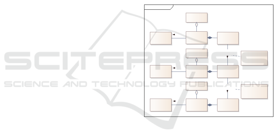
Figure 1: Terms of requirements integration concept.
According to the terms in Figure 1 this approach
uses UML superstructure (Object Management
Group, Inc., 2017) and textual requirements using
SOPHIST template (Pohl & Rupp, 2021) as
representation meta-models.
The second layer is the interpretation layer. This
layer consists of the interpretation models for the
different perspectives onto the system requirements.
For example, if there is a combination of use case
diagrams, activity diagrams and class diagrams
within the requirements model, there will be three
different interpretation models. One interpretation
model is an instance of one interpretation meta-
model. This several interpretation meta-models for
the supported views are derived from the use-cased-
based method to analyse requirements. These meta-
models define the structure of high-quality
class Integration Concept
Meta-Model
Representation
Meta-Model
Model
Requirements
Model
Represented
Requirement
Model
Inter pretation
Model
Meta-Model
Interpretation
Meta-Model
Meta-Model
Inte gr ation M eta-
Model
Model
Integr ation Model
Transformation Rule Set
Integration Rule
Transformation Rule Set
Interpretation Rule
Inter preted
Requirement
Integrated
Requirement
Represention Layer
Inter pretation Lay er
Integration Layer
1..*
0..*
instance
of
1
1..*
1..*0..*
instance
of
1
1..*
1
1..*
will be
transformed to
0..1
1
will be
transformed to
0..1
1
0..1
instance
of
1
MODELSWARD 2025 - 13th International Conference on Model-Based Software and Systems Engineering
290
requirements within one specific view but are not
described within this paper in detail. One example for
the interpretation meta-model for UML activity
diagrams is described in (Rauh et al., 2018a).
The third layer is the integration layer which
contains the integration model. The integration model
consists of integrated requirements derived from the
interpreted requirements of the several interpretation
models. The integrated requirements are structured
according to the integration meta-model defined in
(Rauh et al., 2017).
During requirements integration process the
represented requirements of the requirements model
are transformed to interpreted requirements by
applying transformation rules for interpretation. The
interpreted requirements are parts of the
interpretation model of the specific view. After
finishing the interpretation, the interpreted
requirements are transformed to integrated
requirements by applying transformation rules for
integration.
In contrast to the model-to-model transformation-
based implementation described in (Rauh et al.,
2018a) the different models will be stored in one
common graph. The nodes of this graph are labelled
to differentiate the three layers and the several
interpretation models.
4 GRAPH-BASED
REQUIREMENTS
INTEGRATION
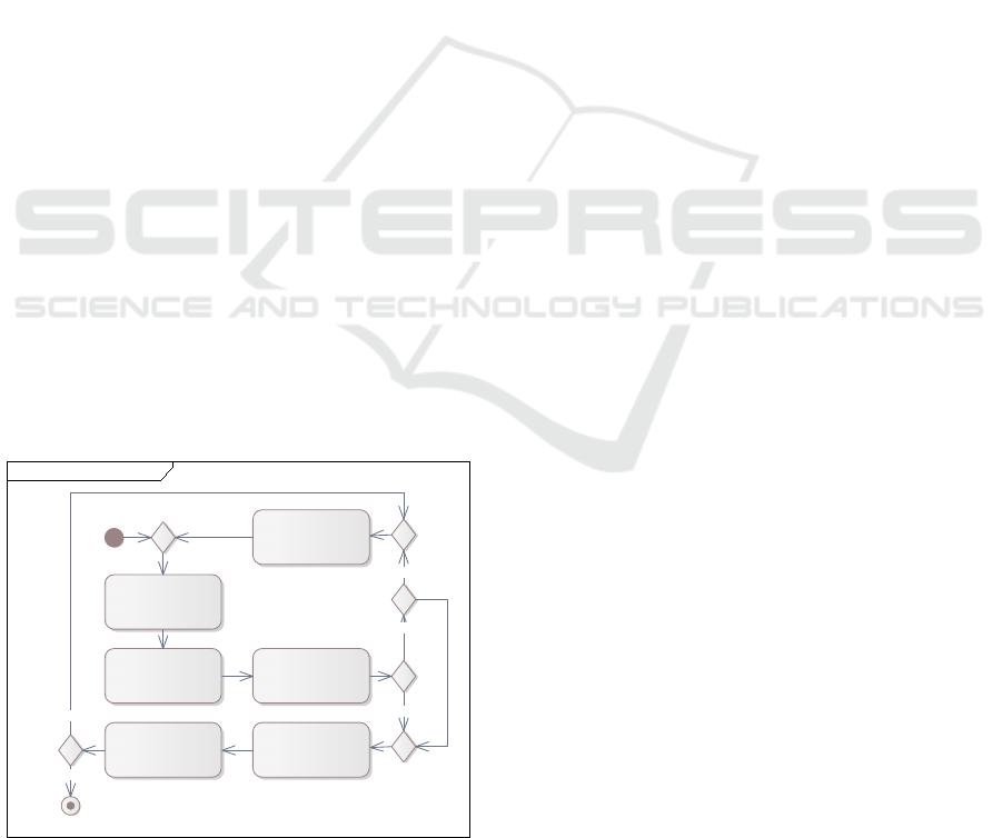
The process for requirements integration and
validation is shown in Figure 2.
Figure 2: Requirements integration and validation process.
As the first step the requirements analyst has to
export the requirements model from the modeling
tool to an XMI file. This XMI file serves as the
foundation for an algorithm which imports the
content of requirements model into the graph. After
import is finished the graph transformation rules are
applied to interpret the imported requirements. If
transformation rules detect any view-specific defects
the requirements analyst has the possibility to edit
these defects in the requirements model and can
repeat the first three steps. The rework of the
requirements model is crucial for critical defects
which result from syntax violations within the source
model. Critical defects prevent the integration of
these parts of the requirements model which led to the
defect. One such critical defect is violation of naming
convention which will be used to integrate natural
language parts of different requirements views. One
such convention and their impact is explained in the
following subsections.
If there are no view-specific defects or the analyst
does not want to edit these defects within the
requirements model algorithms transform the graph
according to the integration rules for the different
interpreted requirements. During this step
interrelations between the interpreted requirements of
different interpretation models will be created using
the structure of the common requirements meta-
model. The resulting graph after applying these
transformations is shown in Figure 5.
As a last step of the integration and validation
process, algorithms apply pattern to the graph to
identify violations of rules for high-quality system
requirements. These rules are derived from the
method for capturing system requirements.
The process shown in Figure 2 is implemented
using jQAssistant (Mahler, 2024) as an infrastructure.
The tool jQAssistant is able to scan source files in
different formats like XML or XMI and stores the
content of these files into graph structure using a
Neo4J database (Graph Database & Analytics, 2024).
Once imported, the graph which contains the raw data
of the UML model is transformed to perform the
measurement. The transformation is realised using
Cypher (Neo4j Graph Data Platform, 2024) scripts
for the Neo4J database in version 3.5 and is executed
by jQAssistant.
4.1 Transformation Rules for
Requirements Interpretation
During the first step, the content of the source model
is interpreted according to pre-defined interpretation
meta-models as mentioned in (Rauh et al., 2018a). As
act Graph-based integ r ation process EN
«Algorithm»
import requirements model
into gr aph
«Algorithm»
apply graph transformation
rules for interpretation
«Algorithm»
apply graph transformation
rules for integration
«Algorithm»
match patter n to v alidate
graph ofintegrated
requirements
update
model?
«Analyst»
edit r equir ements model
solve
critical
defects?
critical
defects
found?
«Analyst»
export r equirements model
to xmi
[no]
[yes]
[no]
[yes]
[yes]
Validation of Requirements Models Using a Graph
291
a result of the transformation, if possible, nodes are
created that represent instances of the classes of the
interpretation meta-models including the attributes of
the classes as attributes of the respective nodes. The
edges of the graph are instances of the associations
between the classes of the meta-model.
One the one hand, the interpretation is used as a
simple syntax check of the source model. If parts of
the source model does not follow the syntax of UML
(e.g. if the modeling tool is less restrictive), this
content cannot be integrated into the common
requirements model but separate nodes representing
the defects for syntax violations are created within the
graph and are associated to origins of the defect.
On the other hand, the interpretation checks
perspective specific rules (e.g. naming conventions of
actions in activity diagrams or of effects in state
charts) the requirements in the source model have to
fulfil. If parts of the source model violate these
perspective specific rules, nodes representing the
defects resulting from violations of the perspective
specific rules are created within the graph. These
nodes are also associated to origins of the defect.
During validation step both kinds of defects are
analysed within the transformed graph and will be
used to create metrics for requirements quality.
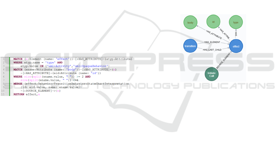
Figure 3: Transformation rule for effects of state charts.
The interpretation rule shown in Figure 3 matches
a specific structure within the graph. This “match”-
clause searches for the structure where one node
labelled as “Element” with the name “effect” has one
“HAS_ATTRIBUTE” edge to another node labelled
as “Attribute”. The first “where”-clause restricts the
result of pattern matching to attributes whose name is
“type” and with the value “uml:Activity” or
“uml:OpaqueBehavior”.
The second “match”-clause searches an
additional “Attribute” node named “body” and an
“Attribute” node named “id” of the “effect”. The
second where clause limits results to effects whose
name is between two and four token to be conform to
the naming convention of effects: <verb> [adjective]
<noun> [adverb].
The “merge”-clause extends the graph and creates
a new node labelled with “Behavior”,
“TransitionBehavior” and “StateChartInterpretation”
to provide the foundation for the integration and the
pattern to validate the graph. The name and id of the
interpreted effect is also stored in the new “Behavior”
node. Furthermore, this resulting node is linked to its
origin in the representation model using an
“SOURCE_ELEMENT” edge. The result of the
mentioned transformation is shown in Figure 4
including source elements (in blue), attributes of
these source elements (in green), several edges
between them and the result of applying the
interpretation rule.
After the nodes are created as mentioned before,
a Natural Language Processing (NLP) pipeline as
defined in (Manning et al., 2014) is applied to check
naming conventions and provide further possibilities
for requirements integration on a semantic level. The
result of this pipeline is also stored as additional
nodes within graph. For example, this pipeline proves
the previously mentioned naming convention for use
cases, activities, actions, and effects in state charts:
<verb> [adjective] <noun> [adverb].
Figure 4: Graph structure after interpretation.
To create this structure the NLP pipeline
tokenizes the names of the respective elements,
lemmatizes these tokens and tags the parts of speech.
As a result, the names of these elements are
represented as separated nodes within the graph. The
previously interpreted effect “Initiate Call” is split
into “Domain Object Term” “Call” and the “Process
Term” “Initiate” as shown in Figure 5.
4.2 Integrated System Requirements
During the second step, the interpreted parts of the
graph will be used as foundation for the integration.
The graph is further extended by additional nodes and
edges to represent the integrated requirements. The
structure of these parts of the graph are defined by the
common requirements meta-model defined in (Rauh
et al., 2017). After integration transformations the
graph contains the source UML model representing
requirements, the interpreted requirements including
defects of the interpretation and the integrated
requirements including defects of the integration.
MODELSWARD 2025 - 13th International Conference on Model-Based Software and Systems Engineering
292
The idea of the requirements integration concept
is to create interrelation between the different
perspectives onto system requirements based on the
natural language parts of each representation and use
them for consistency checks. For example, the effects
of the state charts should be defined as activity or
action of a control flow-oriented view. This
interrelation is realised by so called integrated
“Service” elements which were defined in (Rauh et
al., 2017) to describe all kinds of functions of system
under development. Furthermore, the nouns of these
services (e.g. the use cases, activities, actions, and
effects in state charts) should be defined as class or
attribute of a class within the information model of
the requirements specification. Additionally, the verb
defining the process to be applied by the system under
development has to be defined within a glossary view.
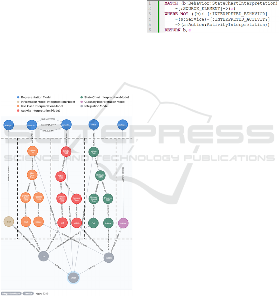
Figure 5 shows a small excerpt of the graph
structure after integration. On top there are the source
elements of the representation layer representing the
model elements requirements model.
Figure 5: Excerpt of graph structure after integration step.
In this example, there is content of five different
views onto system requirements from left to right:
A class “Call” of the information model
A use case “Initiate Call”
An activity “Initiate Call” as use case
refinement
An effect “Initiate Call” of a state transition
A glossary entry “Initiate” with term definition
Figure 6: Quality pattern to match effects which are not
defined in the activity diagrams.
In the middle there are the interpreted parts of the
source element in the different interpretation models.
These interpretation models are separated by colour
and doted lines and show the results of the previously
mentioned analysis of natural language parts.
On the bottom there is one integrated service
within the integration model which is defined by the
function “Initiate” that is applied to the domain object
“Call”. This service node links requirements from use
case perspective, activities, and the state charts on
ways of a semantic level due to natural language
parts. Furthermore, the domain object is linked to an
element within the information model which will
provide further details to this object like attributes.
The definition of the process is part of the glossary
and is also linked to the element of the integration
model. Both parts of the service node are linked to
their sources in the interpretation models.
5 PATTERN MATCHING FOR
REQUIREMENTS VALIDATION
The last step in the graph-based implementation for
assessing the quality of system requirements is the
validation of the graph. For validation there are
pattern that check the defects created during
interpretation and integration of requirements and
pattern that check the graph-structure according to the
defined meta-models.
If graph transformations cannot be performed due
to syntax violations of the UML source model
specific nodes representing the defect are generated.
The first type of pattern shown in Figure 7 searches
all these defect nodes within the graph and lists their
source elements in the requirements model.
Validation of Requirements Models Using a Graph
293
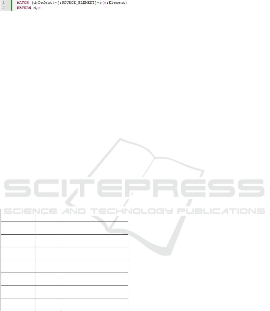
Figure 7: Quality pattern to match defect nodes and their
sources.
The other type of pattern is derived from the
method for capturing system requirements to check
whether the graph structure fits to the structure of the
interpretation and integration meta-models. This
includes the check of missing elements according to
the meta-models, missing links between nodes
regarding a specific interpretation meta-model and
more complex rules for high-quality integrated
requirements.
Figure 6 shows a more complex rule to cross
check if an effect of the state charts is also defined as
action or activity.
The “match”-clause searches all nodes labelled as
“Behavior” and “StateChartInterpretation” which
have an “SOURCE_ELEMENT” edge to another
nod, which represents the source element within the
requirements model. The “where not”-clause checks
the graph structure and filters nodes which are not
linked to a service node. Furthermore, this service
node must have an “INTERPRETED_ACTIVITY”
edge to a node representing an action of activity of the
activity diagrams.
Table 1: Overview of quality pattern and supported quality
characteristics.
Supported
View
Number
of rules
Supported quality
characteristics
Use Case
Dia
g
rams
7 Completeness, Correctness,
Unambi
g
uit
y
, Necessit
y
Activity
Dia
g
rams
6 Completeness, Correctness,
Unambi
g
uit
y
, Necessit
y
State Charts 8 Completeness, Correctness,
Unambiguit
y
Class
Diagrams
5 Completeness,
Unambiguit
y
Sequence
Charts
5 Completeness, Correctness,
Unambi
g
uit
y
Quality
requirements
1 Correctness
Comprehen-
sive rules
21 Completeness, Correctness,
Unambiguity, Necessit
y
Each pattern has assigned at least one quality
characteristic according to IEEE 29148 (IEEE, 2018).
This allows to create overall quality reports which
support the prove of compliance to regulations and
process capability models as stated in the introduction
section of this paper. Table 1 gives an overview of the
defined quality pattern.
6 CONCLUSIONS
The proposed integration concept of requirements
using a graph-based implementation offers several
advantages over informal review techniques and
already existing tool-based model validation.
The first benefit is the integration of an NLP
pipeline to analyse natural language parts within the
requirements model. Thereby, the approach realises
one step towards semantic analysis of the
requirements. The assessment natural language parts
provided enhanced consistency checks and will help
the requirements analysts to create a consistent
requirements model. One major advantage over
traditional tool-based model validation is that the
results of the NLP pipeline are available permanently
for further analysis purposes.
The second benefit is that the approach does not
affect the method for capturing the system
requirements. The requirements analysts must not
adjust their way of working. In comparison to other
formal validation approaches like (Torre, 2016) or
those provided by tool vendors (Sparx Systems,
2022) require extension of the requirements model by
formal aspects using OCL. In the mentioned concept
the documentation language as well as the
requirements management tool remains untouched.
This leads to a third benefit. Assessing the quality
of system requirements does not take any additional
effort of analysts which may help to improve the
acceptance of applying the mentioned concept onto a
real-world systems specification.
The last major benefit is the enhanced traceability
between requirements in different perspectives.
These traces are established automatically by the
integration transformations and support the
requirements analysts during impact analysis of
changes in the system requirements. The graph
structure consisting of nodes and edges provide
formal mechanisms to identify the impact of changes.
While the graph-based approach offers significant
advantages, it is important to acknowledge its
limitations. First of all, there is a high dependence of
the derived interpretation meta-models and quality
rules to the method for capturing the system
requirements. Any deviations from the assumed
methodology will impact the rules for high-quality
requirements, the reference implementation of graph
transformations and pattern matching in the graph.
The ability to import and process UML models in
XMI format might seem to provide tool
independence, but differences in XMI structures and
tool-specific extensions can affect the import into the
graph and may lead to another initial graph structure.
MODELSWARD 2025 - 13th International Conference on Model-Based Software and Systems Engineering
294

Changes in the graph structure require adjustments of
the transformation scripts as well as the pattern for
quality checks.
At the time of authoring this paper, a case study
with a real-world system specification was still in
progress to produce detailed results of the mentioned
approach and seem to acknowledge its possibilities.
To get early feedback to the integration concept and
to show feasibility a constructed example of a
smartphone specification was used.
For future research it might be useful to use the
integrated requirements to generate other
perspectives onto the system requirements. This
would support the analysts to switch between
requirements representations without any additional
effort and loss of information. One use case could be
the generation of a traditional textual client or
supplier specifications based on a high-quality
requirements model.
Another extension might be to apply advanced
techniques for data analysis onto the graph of
requirements and might be a step towards knowledge
engineering or digital twin of the system under
consideration.
REFERENCES
Al-Fedaghi, S. (2021). Validation: Conceptual versus
Activity Diagram Approaches. (IJACSA) International
Journal of Advanced Computer Science and
Applications, Vol. 12, No. 6, 12(6). http://arxiv.
org/pdf/2106.16160
Cziharz, T., Hruschka, P., Queins, S., & Weyer, T. (2024,
July 23). Handbook of Requirements Modeling IREB
Standard. International Requirements Engineering
Board. https://www.ireb.org/content/downloads/19-
handbook-cpre-advanced-level-requirements-modeling/
ireb_cpre_handbuch_requirements_modeling_advance
d_level_de_v2.2.pdf
Graph Database & Analytics. (2024, November 5). Neo4j
Graph Database & Analytics – The Leader in Graph
Databases. https://neo4j.com/
Hausmann, J. H., Heckel, R., & Taentzer, G. (2002).
Detection of conflicting functional requirements in a
use case-driven approach: a static analysis technique
based on graph transformation. In W. Tracz, J. Magee,
& M. Young (Chairs), the 24th international
conference, Orlando, Florida.
IEEE. (2018). 29148-2018 - ISO/IEC/IEEE International
Standard - Systems and software engineering -- Life
cycle processes -- Requirements engineering. IEEE.
https://ieeexplore.ieee.org/servlet/opac?punumber=85
59684
International Electrotechnical Commission. (2009).
Industrial communication networks: Network and
system security (Ed. 1.0, 2009-07). International
standard / IEC: 62443-1-1. IEC Central Office.
International Electrotechnical Commission. (2010).
Functional safety of electrical, electronic,
programmable electronic safety related systems:
International standard (Edition 2.0 (2010-04)).
International Electrotechnical Commission (2015, March
31). Information technology. Process assessment.
Concepts and terminology. BSI British Standards.
International Organization for Standardization (2018). ISO
26262: Road Vehicles - Functional Safety (ISO
26262:2018-02). https://www.iso.org/standard/68383.
html
Kroha, P., Janetzko, R., & Labra, J. E. (2009). Ontologies
in Checking for Inconsistency of Requirements
Specification. In Third International Conference on
Advances in Semantic Processing (SEMAPRO),
Sliema, Malta.
Li, X., Liu, Z., & He, J. (2005, June 16). Consistency
Checking of UML Requirements. In 10th IEEE
International Conference on Engineering of Complex
Computer Systems (ICECCS'05), Shanghai, China.
Mahler, D. (2024). jQAssistant. https://github.com/
jqassistant
Manning, C., Surdeanu, M., Bauer, J., Finkel, J., Bethard,
S., & McClosky, D. (2014). The Stanford CoreNLP
Natural Language Processing Toolkit. In Proceedings
of 52nd Annual Meeting of the Association for
Computational Linguistics: System Demonstrations.
Association for Computational Linguistics. https://doi.
org/10.3115/v1/p14-5010
Neo4j Graph Data Platform. (2024, May 30). Introduction
- Cypher Manual. https://neo4j.com/docs/cypher-
manual/3.5/introduction/
Object Management Group, Inc. (Februar 2014). Object
Constraint Language (OCL™). https://www.omg.org/
spec/OCL/2.4/PDF
Object Management Group, Inc. (Dezember 2017). OMG®
Unified Modeling Language®(OMG UML®).
https://www.omg.org/spec/UML/2.5.1/PDF
Pohl, K., & Rupp, C. (2021). Basiswissen Requirements
Engineering: Aus- und Weiterbildung nach IREB-
Standard zum Certified Professional for Requirements
Engineering Foundation Level (5., überarbeitete und
aktualisierte Auflage). dpunkt.verlag.
Rauh, A., Golubski, W., & Queins, S. (2017). A
requirements meta-model to integrate information for
the definition of system services. In 2017 IEEE
Symposium on Service-Oriented System Engineering.
IEEE / Institute of Electrical and Electronics Engineers
Incorporated.
Rauh, A., Golubski, W., & Queins, S. (2018a). Measuring
the Quality of System Specifications in Use Case
Driven Approaches. In I. Schaefer, D. Karagiannis, A.
Vogelsang, D. Méndez, & C. Seidl (Eds.),
Modellierung 2018 (pp. 151–166). Gesellschaft für
Informatik e.V.
Rauh, A., Golubski, W., & Queins, S. (2018b, March 26–
29). Semantic Integration of System Specifications to
Support Different System Engineering Disciplines. In
Validation of Requirements Models Using a Graph
295

2018 IEEE Symposium on Service-Oriented System
Engineering (SOSE) (pp. 53–62). IEEE.
https://doi.org/10.1109/SOSE.2018.00016
Sparx Systems (Ed.). (2022, January 22). Model
Validation | Enterprise Architect User Guide.
https://sparxsystems.com/enterprise_architect_user_gu
ide/14.0/model_domains/model_validation.html
Torre, D. (2016). Verifying the Consistency of UML
Models. In 2016 IEEE International Symposium on
Software Reliability Engineering Workshops
(ISSREW) (pp. 53–54). IEEE.
https://doi.org/10.1109/ISSREW.2016.32
VDA Working Group 13 (2023, November 29).
Automotive SPICE Process Assessment / Reference
Model. https://vda-qmc.de/wp-content/uploads/2023/
12/Automotive-SPICE-PAM-v40.pdf.
MODELSWARD 2025 - 13th International Conference on Model-Based Software and Systems Engineering
296
