
STELLA
+
: Expanding the Research Potential for Long-Term Deep
Brain Stimulation Studies in Freely-Moving Rodents
Franz Plocksties
1 a
, Christoph Niemann
1
, Mareike Fauser
2
, Alexander Storch
2
,
Dirk Timmermann
1
and Christian Haubelt
1
1
Institute of Applied Microelectronics and Computer Engineering, University of Rostock, Germany
2
Department of Neurology, University of Rostock, Rostock, Germany
Keywords:
Deep Brain Stimulation, Long-Term, Preclinical DBS Device, Adaptive DBS.
Abstract:
Rodent models are essential for our understanding of Deep Brain Stimulation (DBS) mechanisms. How-
ever, most existing preclinical devices lack to support the broad experimental range required for modern DBS
approaches. This paper presents the neurostimulation system STELLA
+
, which aims to enhance the scope
of long-term DBS research in rodent models. STELLA
+
upgrades the previous STELLA system that has
been successfully used in several rodent studies. It features technical and architectural enhancements to in-
crease performance and functionality for long-term DBS experiments. Initial in vitro findings demonstrate that
STELLA
+
delivers charge-balanced, current-controlled pulses with high accuracy across a range of stimula-
tion settings up to a compliance voltage of 4.3 V. With a maximum current consumption of 25.1 µA at 4.3 V
in bilateral DBS-on mode, STELLA
+
enables long-term experiments of 6.8 weeks using a 29 mAh lithium-
ion battery. Additionally, STELLA
+
includes a Bluetooth Low Energy module and the capability to acquire
and compute on-board physiological data, enabling adaptive DBS applications. All these features are housed
within a compact size of 21x14.5x4 mm, minimizing the impact on rodents. Compared to the other state-
of-the-art DBS devices, STELLA
+
demonstrates enhanced efficiency in stimulus generation and a uniquely
comprehensive feature set.
1 INTRODUCTION
Deep Brain Stimulation (DBS) has emerged as a re-
markable therapeutic approach for the management
of various neurological and psychiatric disorders. By
delivering electrical pulses to specific brain regions
through implanted electrodes, DBS has shown sig-
nificant results in symptom control and improving
patients’ quality of life. While the therapy is well-
established for the treatment of movement disorders,
such as Parkinson’s disease, dystonia and tremor, its
potential for other diseases is also being explored
(Harmsen et al., 2020). However, the precise mech-
anisms by which DBS develops its therapeutic ef-
fects are still under active investigation (Hamani and
N
´
obrega, 2010; Jakobs et al., 2019). To address the
open questions, preclinical in vivo experiments are es-
sential. Rodent models have been widely employed in
DBS research, allowing for investigations into elec-
trophysiological, neurochemical and behavioral as-
a
https://orcid.org/0000-0003-0433-7703
pects (Ruiz et al., 2022). However, the progress of
past studies has been impeded by runtime-restricted
and bulky stimulation devices mounted on the ro-
dent’s head (K
¨
olbl et al., 2016; Fluri et al., 2017;
Pinnell et al., 2015; Pinnell et al., 2018; Forni et al.,
2012; Liu et al., 2017; Ewing et al., 2013) or back
(Kouzani et al., 2017; Badstuebner et al., 2017; Heo
et al., 2015). These setups not only led to a signif-
icant strain on the animals, but also resulted in fre-
quent device failures, e.g. due to cable breaks and
mounting issues caused by the animals’ movement.
To overcome these limitations, the fully implantable
stimulation device called STELLA (software defined
implantable modular platform) was introduced, en-
abling reliable and long-term stimulation in rodents
(Plocksties et al., 2021a). Furthermore, this device
is highly suitable for sensitive behavioral studies in
DBS research as it supports the refinement aspect
of the 3R principles through the reduction of strain
for the animals (D
´
ıez-Solinska et al., 2022). How-
ever, despite promising results from rodent studies
conducted with STELLA (Plocksties et al., 2021a;
74
Plocksties, F., Niemann, C., Fauser, M., Storch, A., Timmermann, D. and Haubelt, C.
STELLA+: Expanding the Research Potential for Long-Term Deep Brain Stimulation Studies in Freely-Moving Rodents.
DOI: 10.5220/0013305200003911
Paper published under CC license (CC BY-NC-ND 4.0)
In Proceedings of the 18th International Joint Conference on Biomedical Engineering Systems and Technologies (BIOSTEC 2025) - Volume 1, pages 74-87
ISBN: 978-989-758-731-3; ISSN: 2184-4305
Proceedings Copyright © 2025 by SCITEPRESS – Science and Technology Publications, Lda.
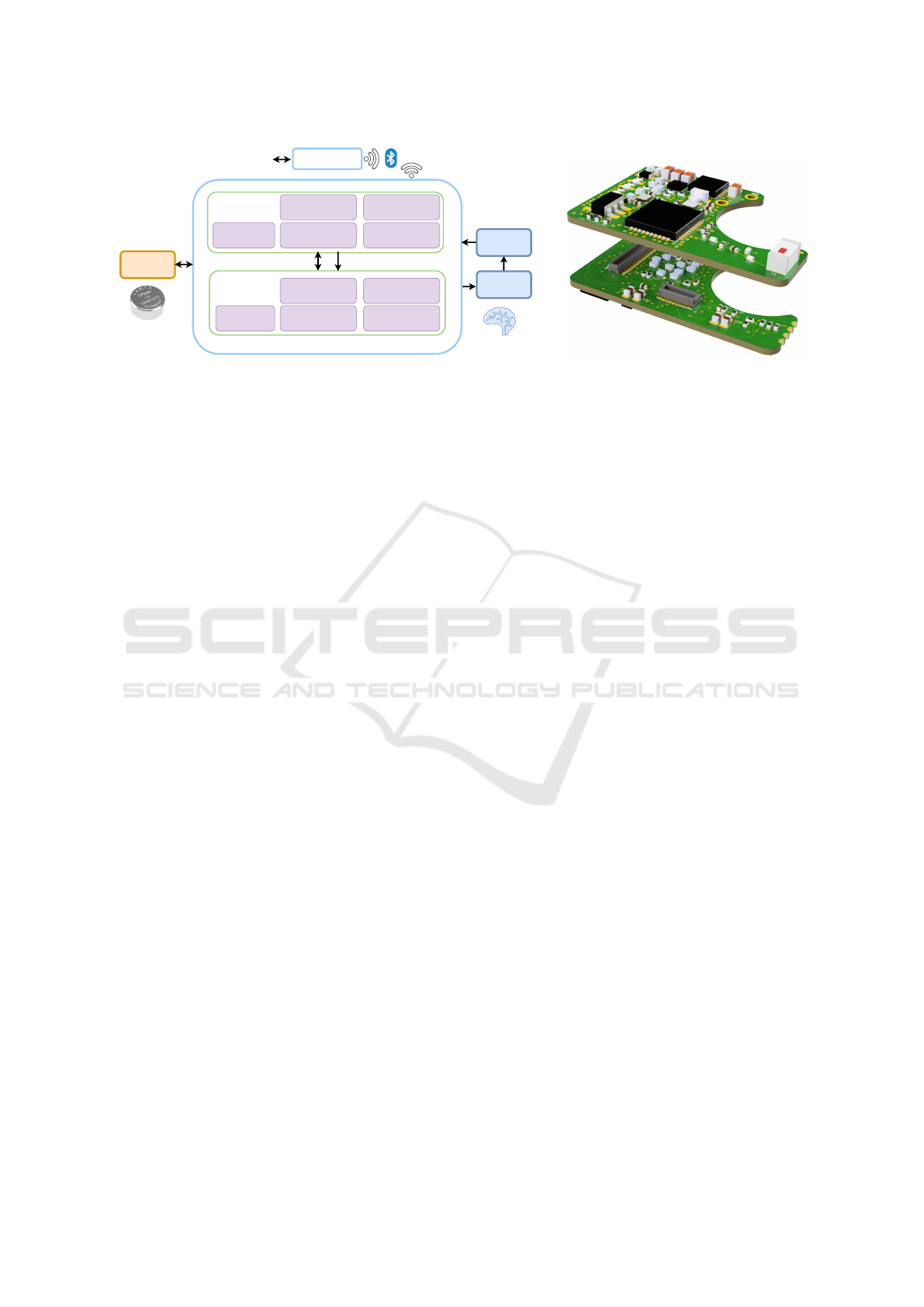
Implant Comm.
(LEDs, BLE, Magn.)
Battery &
Power Management
Temperature Sensor
Level Conversion
Upper PCB
Lower PCB
Li-ion
Battery
Deep Brain
Stimulation
SIG
PWR
I/V Generation of
DBS Pulses
3D Accelerometer
Rechargeable over
electrode leads
Impedance
Characterization
Built-in Self-test
Extracorporeal
Device
Feedback
nRF52 µ-Controller
(Processing + BLE)
MSP430 µ-Controller
(DBS Management)
Laboratory
Infrastructure
(a) (b)
Figure 1: (a) STELLA
+
system overview. (b) 3D design of the upper and lower PCB.
Plocksties et al., 2022; Koschay et al., 2022; Statz
et al., 2023a; Statz et al., 2023b), a crucial gap re-
mains. Like most other state-of-the-art preclinical
DBS devices, STELLA has limitations in support-
ing a wide range of experimental applications, includ-
ing research on adaptive DBS (aDBS). In clinical ap-
plication, aDBS aims to optimize and individualize
therapeutic outcomes by dynamically adjusting the
stimulation parameters based on feedback data (Neu-
mann et al., 2023). As research into suitable biomark-
ers and control methods is still ongoing, the transla-
tion of aDBS between clinical and laboratory settings
is essential. To address this gap, a novel DBS de-
vice named STELLA
+
has been designed that builds
on the strengths of its predecessor while providing
innovative features, which significantly increase ex-
perimental versatility. Key improvements include a
more functional stimulation unit, multiple sensors,
on-board signal processing capabilities and wireless
connectivity, enabling researchers to explore diverse
stimulation strategies in rodents.
This paper demonstrates the start-up phase of
STELLA
+
, focusing on the technical implementa-
tion and performance analysis of the stimulation unit.
Section 2 describes the technical specifications of
STELLA
+
in detail. Section 3 presents performance
metrics of STELLA
+
from in vitro experiments and a
comprehensive overview of its feature set compared
to state-of-the-art devices in this field. Finally, sec-
tion 4 summarizes the findings.
2 TECHNICAL REALIZATION
2.1 System Overview
STELLA
+
utilizes a two-stacked PCB design in or-
der to double available component area compared to
a standard single PCB configuration (see Fig. 1 (b)).
The PCBs are stacked together using miniaturized
connectors (Molex 505417-3410) allowing for the
transfer of power and signals between the two boards.
Fig. 1 (a) illustrates the system overview, highlighting
the functional distribution between the PCBs.
The upper PCB is responsible for battery and
power management, while also housing a Bluetooth
Low Energy (BLE) module for wireless communica-
tion. It also includes a magnetic sensor for triggering
basic device tasks and LEDs (red, green, IR) for sta-
tus indication. Additionally, it incorporates sensory
units, including a temperature sensor for monitoring
the animal’s temperature and a circuit for character-
izing the impedance of the electrode and tissue com-
ponent over a broad spectrum (details not provided in
this paper). On the other hand, the lower PCB focuses
on the generation of charge-balanced DBS pulses for
two channels, including an appropriate level transla-
tion to ensure compatibility between two voltage do-
mains (see Section 2.2.3, 2.3.4). It also incorporates a
built-in self-test to verify whether the electrical stim-
ulation is within a valid range. Finally, it integrates a
3-axis accelerometer sensor for motion sensing of the
animal.
2.2 Power Management
The power management of STELLA
+
is conceptually
presented in Fig. 2(a).
2.2.1 Low-Power Approach
STELLA
+
has been designed to be highly modular,
allowing unused modules to be selectively powered
down to the nA range via dedicated EN signals or the
system bus. This approach permits the platform to
be used in an energy-efficient fashion for each spe-
cific application. Furthermore, the platform utilizes
two microcontrollers to effectively manage various
STELLA+: Expanding the Research Potential for Long-Term Deep Brain Stimulation Studies in Freely-Moving Rodents
75

tasks. The nRF52833, which is built around a 32-
bit ARM Cortex-M4, is used for computationally in-
tensive tasks such as adaptive DBS algorithms. Ad-
ditionally, the nRF52833 includes an RF transceiver
module supporting Bluetooth Low Energy (BLE) for
wireless communication with the outside world. In
contrast, the MSP430FR2355 microcontroller, which
features an ultra-low power architecture, is responsi-
ble for controlling and monitoring the stimulation sig-
nals.
2.2.2 Battery
The platform is powered by the rechargeable Li-
ion button cell CP9440 A4X from VARTA (VARTA,
2019) providing a capacity of 29 mAh. With its com-
pact dimensions of Ø9.4x4 mm, and low weight of
0.9 g, this battery is highly suitable for applications
with critical space.
2.2.3 Voltage Regulation
The previous STELLA implements a unified ap-
proach, where the control and stimulation unit share
the same supply voltage generated by a boost con-
verter. The boost converter was configured to con-
vert the 3 V battery voltage into a system voltage of
up to 3.7 V, allowing for a higher compliance volt-
age if needed. The unified approach offers the ad-
vantage of low circuit complexity, but achieves a low
compliance voltage only due to low maximum toler-
able supply voltage of the microcontroller and sen-
sors. In STELLA
+
, a Li-ion battery (A4X) operating
within a voltage range of 3 to 4.3 V is used as power
source. In order to overcome the compliance volt-
age limitations of STELLA, a dual-VDD approach
was applied, in which the control and stimulation unit
was split into separate voltage domains. The control
unit, including processors and sensors, is powered by
an LDO (Low-Dropout) regulator (TPS7A0228) that
provides a stable 2.8 V rail (V
DD1
). In contrast, the
stimulation unit is connected to a flexible buck-boost
converter topology. The boost (MAX17227A) and
buck (MAX38642A) converter are single ICs with
their outputs tied together. Each converter has an
EN pin that is used to enable or disable the outputs.
When disabled, the converter completely disconnects
the load. The enable signal (EN
DC/DC
) is driven by
the MSP430 and is routed directly to the boost con-
verter and is inverted (74LVC1G04) for the buck con-
verter. This configuration ensures that only one con-
verter is active at any given time, preventing con-
flicting voltage outputs. The output voltage of each
converter is controlled by an individual digital poten-
tiometer (AD5142A) in rheostat mode via I
2
C. This
topology enables the supply voltage for the stimula-
tion unit (V
DD2
) to be scaled either above or below the
battery voltage over a range of 2.5 V and 5.2 V. Com-
bined with the built-in self-test (BIST) that identifies
the maximum voltage at the end of the DBS pulse (see
Section 2.3.7), this method enables energy-efficient
adaptation of the supply voltage for the stimulation
unit according to the load impedance requirements.
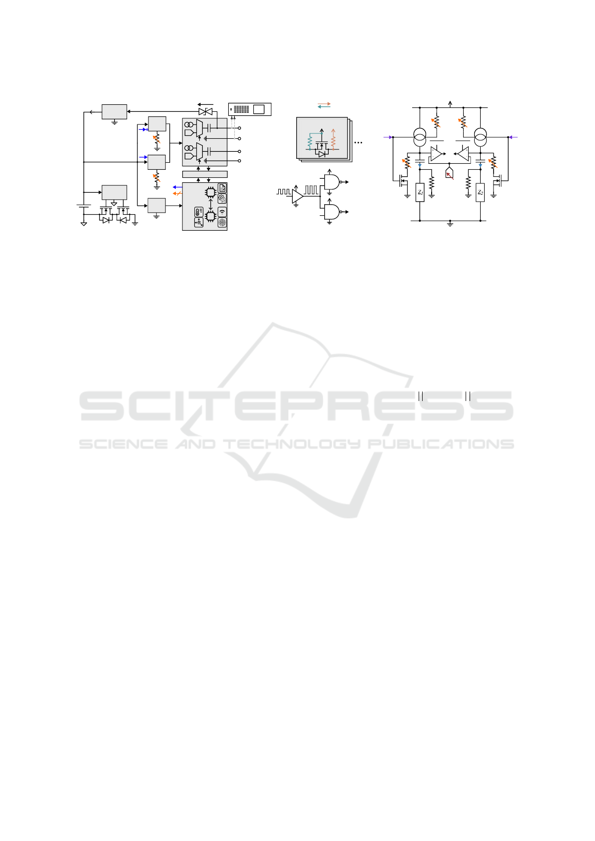
2.3 Stimulation Unit
The stimulation unit is presented conceptually in
Fig. 2(a) and in detail in Fig. 2(c), while the level
translation design is shown in Fig. 2(b).
2.3.1 Multi-Modal Architecture
STELLA
+
features a multi-modal architecture ca-
pable of generating both charge-balanced current-
controlled and charge-balanced voltage-controlled
DBS pulses, both provided by clinical DBS de-
vices. The MSP430 controls a 2:1 analog switch
(TMUX1136) that enables the selection between the
stimulation modes for each channel. The current-
controlled mode is generally the preferred configura-
tion, as it maintains a constant current regardless of
load impedance changes (Kandadai et al., 2023; Hui
et al., 2020; Lempka et al., 2010). Therefore, this
mode is particularly optimized for energy efficiency
and is the primary focus of this section. In view of
current developments in other medical fields, such as
traumatology, the voltage-controlled mode may also
be suitable for other areas of application (Raben et al.,
2024; Nicksic et al., 2022; Klinder et al., 2024).
To this end, STELLA
+
incorporates a 10-bit DAC
(DAC6311) for each channel controlled by the SPI
(Serial Peripheral Interface) bus, enabling the genera-
tion of any required voltage-driven waveform for the
research objective. To ensure that only the AC com-
ponent of the DAC signal, which is typically required
in these application domains, contributes to the stimu-
lation, a blocking capacitor is incorporated that forms
a high-pass filter with the load. This capacitor is posi-
tioned behind the multiplexer to provide the current-
controlled mode with a safety feature for the DBS ap-
plication (see Section 2.3.7).
2.3.2 Generation of Current-Controlled DBS
Pulses
The dual-channel design for generating current-
driven DBS pulses builds on the previous STELLA
architecture, utilizing an MSP430 microcontroller to
precisely control the current amplitude, frequency and
pulse width of the DBS pulses. The dual-channel
BIODEVICES 2025 - 18th International Conference on Biomedical Electronics and Devices
76
Channel 1
L H
(I²C, SPI, EN
x
)
PWM
Ch1(H)
PWM
Ch2(H)
Protector
V
Bat
5.4 V
9.6 V
10 mA
V
DD2
V
DD1
V
DD2
Boost
Buck
LDO
Power Source
nRF
MSP
Charger
Channel 2
Level Translation
L
STIM
CTL
EN
Ch1(H)
IQ
1
I
Sel1
I
Out1
I
Out2
I
Sel2
IQ
2
EN
Ch2(H)
H
15 V
C
B1
C
B2
i
1
i
2
EN
DC/DC
PWM
(L)
PWM
(H)
I²C
PWM
Ch1(H)
PWM
Ch2(H)
V
DD2
V
DD2
V
DD2
(a) (b) (c)
DP
1
DP
3
||
DP
4
DP
5
||
DP
6
DP
2
H
L
V
DD1
V
DD2
10 MΩ
10 MΩ
SHDN
1(H)
V
C1(H)
V
Ref
V
C2(H)
SHDN
2(H)
OA
1
OA
2
Figure 2: Architecture of STELLA
+
. (a) Block diagram illustrating the concept of battery and power management. (b) Level
translation design. (c) Detailed circuitry of the stimulation unit for generating current-controlled and charge-balanced DBS
pulses (adapted from (Plocksties et al., 2021a)).
capability is enabled by a dedicated constant current
source (PSSI2021SAY) for each stimulation channel
which allows the current amplitude to be adjusted
individually. The assumption that a single current
source’s output will result in the half current am-
plitude by connecting the other microelectrode par-
allel to its output is invalid due to differing load
impedances for each channel, as is the case in (K
¨
olbl
et al., 2016). The differences in load impedance are
due to several factors, including the different conduc-
tivity values of white and grey matter (Gabriel and
Gabriel, 1996; Hasgall et al., 2022; Koessler et al.,
2017), the highly dynamic biological encapsulation
processes that surround the electrodes after insertion
(Evers et al., 2022; Lempka et al., 2009), and inherent
manufacturing variations in the electrodes themselves
(Payonk et al., 2025). Furthermore, it is not recom-
mended to achieve a current-controlled stimulation by
varying the resistor in series with a voltage source as
is the case in (de Haas et al., 2012), or by adjusting
the output voltage of a voltage source as is the case
in (Liu et al., 2017). First, these approaches require
frequent active readjustment due to the dynamic load,
which might be energy-intensive. Second, the result-
ing current amplitudes can only be considered con-
stant on a macroscopic time scale. At a microscopic
level, the system still behaves like a voltage source,
which cannot maintain a constant current during the
pulse duration due the capacitive component of the
impedance load (see (de Haas et al., 2012)), resulting
in only semi-current-controlled stimulation.
In STELLA
+
, both current sources (IQ
1
,IQ
2
) are
controlled by the MSP430’s PWM (Pulse-width mod-
ulation) signal, that carries the frequency and pulse
width information, resulting in synchronized DBS
pulses for both channels. Similar to STELLA, the
MSP430’s clock in STELLA
+
is sourced by an ex-
ternal 32,768 Hz crystal, thereby enabling the micro-
controller to operate in ultra-low power mode. Con-
sequently, the pulse width and frequency can be ad-
justed in approximately 30 µs increments. In or-
der to adjust the stimulation current of the previous
STELLA, a digital potentiometer in rheostat mode
in parallel with a fixed resistor is used to tailor the
highly non-linear output of the current source with
high resolution between 50 µA and 100 µA. However,
if higher stimulation currents with high accuracy were
required, the resistor had to be resoldered. In con-
trast, STELLA
+
employs two digital potentiometers
(AD5143) in parallel (DP
3
DP
4
, DP
5
DP
6
, all op-
erating in rheostat mode) for adjusting the stimula-
tion current of each channel, allowing high-resolution
adjustments above 100 µA without the need for hard-
ware modifications. Note that since the output current
of the used current source varies with supply voltage,
it must be calibrated across the entire supply voltage
range. The same applies to temperature, requiring the
output current to be calibrated under in vivo condi-
tions.
2.3.3 Compliance Voltage
Most existing stimulation devices for rodents are de-
signed for current-controlled stimulation, which en-
sures constant current delivery despite variations in
load impedance (see Table 1). Maintaining a constant
current requires sufficient compliance voltage to ac-
commodate the diverse range of electrode configura-
tions, stimulation parameters and electrode encapsu-
lation caused by the biological response. In the ex-
isting literature on DBS devices, it is frequently as-
sumed that the supply voltage of the current source is
equal to the maximum voltage that the current source
can provide for the load impedance. This assump-
tion is incorrect, as the internal resistance of a cur-
rent source leads to a voltage drop that reduces its
maximum output voltage. This voltage drop varies
depending on the type of current source, but is typ-
STELLA+: Expanding the Research Potential for Long-Term Deep Brain Stimulation Studies in Freely-Moving Rodents
77

ically around 1 V. The current source’s supply volt-
age minus the internal voltage drop is called compli-
ance voltage. This consideration is especially impor-
tant for DBS devices operating with a current source’s
supply voltage in the region of 3 V (Plocksties et al.,
2021a; Fleischer et al., 2020; Grotemeyer et al., 2024;
Fluri et al., 2017; Kouzani et al., 2017). While these
devices typically feature a low current consumption,
their relatively low compliance voltage below 3 V in-
creases the risk that the constant current cannot be
maintained within the pulse width when using stan-
dard stimulation protocols and standard electrodes.
This can be especially critical when integrated mon-
itoring capabilities are lacking to check whether the
stimulation is in a valid range. In contrast, circuit de-
signs that allow for higher compliance voltages result
in significantly increased current consumption, even
reaching the mA range in some cases (Ewing et al.,
2013; Pinnell et al., 2018; Pinnell et al., 2015; K
¨
olbl
et al., 2016; Adams et al., 2019), which negatively
impacts the ratio between battery volume and run-
time. Furthermore, considering that typical rodent
stimulation protocols use stimulation currents of no
more than 100 µA for 60 µs (Reese et al., 2009; Ev-
ers et al., 2022; Leblois et al., 2010; Heerdegen et al.,
2021; Paap et al., 2021; Zhang et al., 2024), devices
operating at such high compliance voltages may be
regarded as oversized and consequently inefficient.
Using the bipolar microelectrode PI-SNEX-100 (Mi-
croprobes, Gaithersburg, USA), which is widely used
in rodent DBS studies, our ex vivo voltage measure-
ments in rodent brain tissue showed that the maxi-
mum voltage of the DBS pulse never exceeded 3.5 V
for a 100 µA/60 µs pulse with a frequency of 130 Hz.
STELLA
+
is designed for high energy efficiency
to facilitate long-term experiments with a low battery
volume while offering sufficient compliance voltage
up to 4.3 V to support the most common stimulation
setups in DBS research using rodent models (see Sec-
tion 3.2, 3.3).
2.3.4 Level Translation
Given the 2.8 V operating voltage of the MSP430
and the up to 5.2 V domain of the stimulation unit
in STELLA
+
, an appropriate level translation de-
sign is required that meets the requirements for ultra-
low power consumption. In order to level-shift the
low-voltage PWM signal (PWM
L
), which controls
the rectangular stimulation pulses, to the higher volt-
age rail (PWM
H
), a translation buffer (74LV1T34) is
used. Although the additional supply current in typ-
ical voltage translators increases significantly as the
input voltages diverge from the supply voltage, this
approach remains feasible due to very low duty cy-
cles encountered in DBS, such as a pulse width of
60 µs and a frequency of 130 Hz. A dedicated IC is
critical in this case as it ensures excellent signal in-
tegrity across the entire translation range required for
the sharp rise and fall time of the rectangular wave-
form.
All other signals, including the I
2
C bus, SPI bus
and EN signals, are level translated using n-channel
MOSFETs (CSD15380F3) together with pull-up re-
sistors, allowing reliable communication between the
voltage domains. For unidirectional operation, low-
to-high translation is achieved by a pull-up resistor at
the high side, while high-to-low communication uti-
lizes a pull-up at the low side. For bidirectional com-
munication, as required by the I
2
C, pull-up resistors
are implemented on both sides.
2.3.5 Charge Balancing
Any system designed for the electrical stimulation
of tissue must keep the voltage across the working
and counter electrode within the safe electrochemical
window to avoid harmful byproducts to the surround-
ing tissue. Since biological tissue is mainly composed
of water, exceeding a certain voltage threshold leads
to the electrolysis of water (Boehler et al., 2020).
This irreversible process can cause tissue damage due
to the formation of oxygen and hydrogen gases, along
with significant pH changes (Boehler et al., 2020;
Huang et al., 2001). In the scenario of DBS, each
stimulation pulse charges the double-layer capaci-
tance that is formed at the electrode-tissue interface.
It is critical to properly discharge this capacitance
between pulses to prevent charge accumulation over
time, ensuring that no sustained DC offset above the
decomposition voltage of water can develop.
To address this, STELLA
+
uses the established
passive charge balancing method by connecting the
stimulation electrode to ground through an adjustable
resistor, similar to STELLA. However, this method
has been slightly modified for STELLA
+
by using a
fast-switching n-channel MOSFET instead of an ac-
tive switching IC, resulting in negligible power con-
sumption of this method. This n-channel MOSFET is
controlled by the high-voltage PWM signal for each
channel (PWM
Ch1(H)
, PWM
Ch2(H)
). During the pulse-
off phase, the MOSFET is activated, creating a dis-
charge path for the double-layer capacitor. During
the pulse-on phase, it enters the high impedance state,
preventing interference with the stimulation pulse.
The passive charge balancing approach induces a cur-
rent reversal pulse. Without an additional resistor, the
peak value of the reversal pulse depends on the DBS
voltage and current value at the end of the pulse as
well as the value of the electrolyte resistance (access
BIODEVICES 2025 - 18th International Conference on Biomedical Electronics and Devices
78

resistance). The larger the peak value, the more it
could counteract the desired physiological effect of
the stimulation impulse (Merrill et al., 2005). There-
fore, a digital potentiometer (AD5143, 100 kΩ) in
rheostat mode is used in the discharge path of each
channel to reduce this peak value (DP
1
, DP
2
). Note
that the double-layer capacitor must be fully dis-
charged before the next pulse is generated, as other-
wise control over the electrode voltage will be lost.
The time required for full discharge should include a
sufficient safety margin to account for the various bi-
ological processes influencing the load impedance.
2.3.6 Independent Channel Control
While STELLA was developed for the simultaneous
control of two channels, the new design offers the op-
portunity to activate or deactivate each DBS chan-
nel independently. This is achieved by connecting
the high-voltage PWM signal (PWM
H
) to two NAND
gates, with the other input of each gate connected to
a level-shifted EN signal (EN
Ch1(H)
, EN
Ch2(H)
) con-
trolled by the MSP430. This feature allows for re-
duced current consumption by deactivating the un-
used channel in unilateral operation, which is of
special importance in unilateral disease models, e.g.
the 6-hydroxydopamine model of Parkinson’s disease
(Ungerstedt, 1968). Furthermore, in the case of adap-
tive DBS (aDBS) it enables individual on-off control
for both channels simply by switching the enable sig-
nals. The effectiveness of the on-off control scheme
was demonstrated in the study by (Evers et al., 2024).
2.3.7 Safety and Reliability
The stimulation unit includes a DC blocking capaci-
tor of 20 µF placed in series with both current sources
(C
B1
, C
B2
). This capacitor acts as a safety measure for
the subject, preventing high faradaic currents if a sus-
tained, high DC voltage occurs at the electrode in the
event of a fault. However, it has been demonstrated
that even when perfectly charge-balanced stimulation
is applied, the blocking capacitor will generate an off-
set voltage at the electrode-tissue interface (van Don-
gen and Serdijn, 2016). To prevent the offset voltage
potentially exceeding the water window, a high-ohmic
resistance of 10 MΩ was placed in parallel to the load
impedance for each channel. This allows an effective
discharge path for the imbalanced charge, contribut-
ing to minimizing the offset voltage (see Section 3.2).
Furthermore, the 10 MΩ resistor has a negligible im-
pact on the stimulation current. For typical stimula-
tion currents above 50 µA that require the maximum
current source’s output voltage, this would result in a
reduction of the stimulation current of only less than
1 %.
In DBS studies including rodents, typical defects
such as shorted or open electrodes as well as an ex-
cessive load impedance are frequently encountered
(Plocksties et al., 2021a; Plocksties et al., 2022). If
these issues remain undetected, they can have a con-
siderable impact on DBS experiments, as they have
the potential to confound the experimental results and
conclusions. Particularly when using backpacks or
head-mounted DBS systems, the failure rate is con-
siderable (Plocksties et al., 2021a). Therefore, it is
crucial to integrate a method that reliably detects these
problems. Similar to STELLA, STELLA
+
incorpo-
rates a built-in self-test (BIST) that monitors and re-
ports such issues. In a nutshell, the maximum voltage
at the end of the DBS pulse is determined by gradu-
ally lowering the reference voltage at the inverting in-
put of a comparator. As a slight improvement over the
previous version, a dedicated 10-bit DAC (DAC6311)
is used for generating the reference voltage (V
Ref
) via
SPI instead of an 8-bit digital potentiometer, effec-
tively increasing the accuracy of this measurement.
2.4 Battery Management
The circuitry of STELLA
+
is designed for a recharge-
able Li-ion battery as power source, replacing CR or
SR button cells commonly used in existing rodent
stimulators. This eliminates the need for frequent
battery replacement. Additionally, the proposed
circuit design enables recharging the battery directly
via the electrode leads. This dual functionality
is particularly advantageous for fully implantable
stimulators, where the battery typically cannot be
replaced or recharged without damaging the encap-
sulation. The battery management of STELLA
+
is
conceptually presented in Fig. 2(a).
2.4.1 Battery Protection
When using Li-ion batteries, following the safety pro-
tocols is essential, especially when implanted into liv-
ing beings. Therefore, the circuit design has to con-
tain adequate safety mechanisms to safeguard Li-ion
batteries against overcharge, overdischarge, overcur-
rent and short-current. To address these safety re-
quirements, we used a battery management IC (S-
82A1ACA-I6T1U) in combination with two exter-
nal n-channel MOSFETs resulting in disconnecting
the GND potential if any value falls outside the
valid range specified in the technical handbook from
VARTA (VARTA, 2019). Falling below the overdis-
charge voltage of 3 V, this IC transitions to a power-
down mode wherein it consumes 50 nA only, thus
STELLA+: Expanding the Research Potential for Long-Term Deep Brain Stimulation Studies in Freely-Moving Rodents
79
preventing damage to the cell through continued dis-
charge. A second layer of protection is provided
by VARTA’s vent holes integrated into the battery
(VARTA, 2019). These vents ensure that any excess
pressure is released to guarantee safety. For this, it
must be ensured that the encapsulation of the device
provides sufficient space for expansion.
2.4.2 Battery Recharge
For recharging the A4X, a battery charger IC
(BQ25100A) is used, configured with a charging limit
of 4.3 V and a charge current of 10 mA. To allow
the cable that transmits the stimulation signal to the
electrode to also serve as a path for supplying power
to the input of the charger IC, a bilateral TVS diode
(SP0201B-ELC-01UTG) with a breakdown voltage
of ±9.6 V/1 mA is used. This low-capacitance diode
prevents interference between the charger IC and the
stimulation output. As the maximum voltage that
the DBS pulse reaches is 4.3 V, this breakdown volt-
age is far below this value. Considering the volt-
age drop across the TVS diode with a charge cur-
rent of 10 mA, the power source has to output approx.
15 V to provide a sufficiently high input voltage for
the charger IC. A blocking capacitor in series to the
current source (C
B1
), already used for protecting the
brain tissue in a failure event, serves as high-voltage
protection for the current source and the circuitry for
the built-in self-test.
3 RESULTS AND DISCUSSION
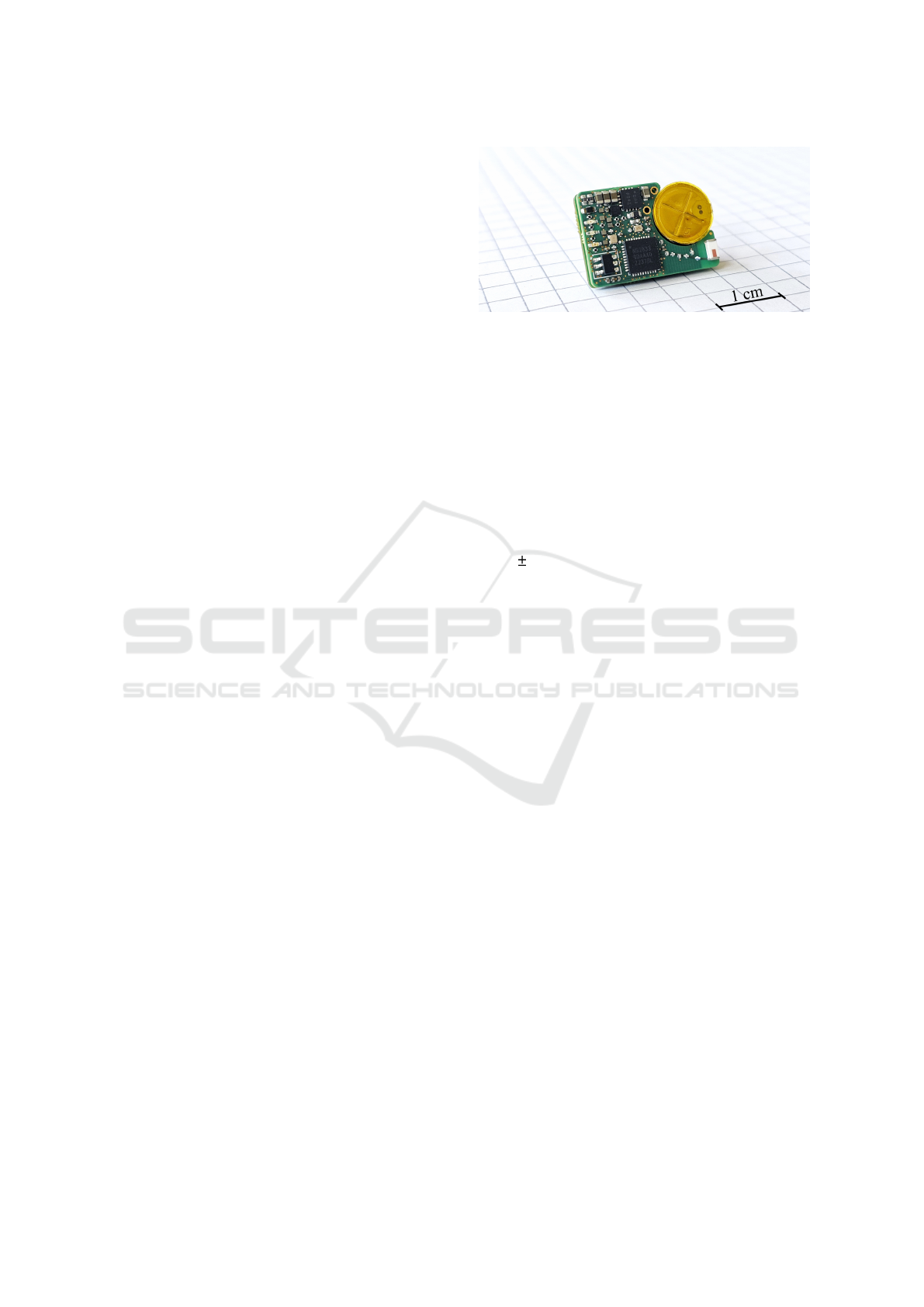
3.1 Device Specifications
The PCBs are designed in a six-layer configuration
with a high wiring density per unit area, enabling a
small footprint despite a high IC package area. The
manufactured boards measure 21x14.5 mm with a cir-
cular cut-out of 9.5 mm diameter to accommodate the
battery for the overall system in a space-saving man-
ner (see Fig. 3). When the PCBs are stacked, the total
height is 4 mm, matching the height of the battery.
The total PCB volume, calculated as 21x14.5x4 mm
minus the volume of the cut-out, results in 935 mm
3
.
The PCB weight is 1.2 g, while the complete device
including the battery weighs 2.1 g. When combined
with the reliable and compact encapsulation method
presented in (Plocksties et al., 2021b), for example,
the device specifications might be highly suitable for
fully subcutaneous implantation in small rodents.
Figure 3: STELLA
+
demonstrated on graph paper, featur-
ing the PCB stack and Li-ion battery.
3.2 In Vitro Characterization of the
Stimulation Unit
3.2.1 Measurement Setup
The performance of the stimulation unit of STELLA
+
for current-controlled DBS was evaluated in an in
vitro setting. A PI-SNEX-100 microelectrode was
connected to one channel of STELLA
+
and im-
mersed in a NaCl conductivity standard solution of
0.199 0.002 S m
−1
at 25 °C. This conductivity was
chosen because it lies within the range of reported
conductivity values for white and grey matter (Gabriel
and Gabriel, 1996; Hasgall et al., 2022; Koessler
et al., 2017; Akhtari et al., 2006), considering the
relevant frequency range derived from the frequency
spectrum of the DBS signal (Badstuebner et al., 2017;
Gimsa et al., 2005).
For the measurements presented in Fig. 4(a)-(c),
the current amplitude was increased by 50 µA and
the pulse width was increased by 30 µs simultane-
ously, starting with 50 µA/60 µs and ending with
200 µA/150 µs. The frequency was set to 130 Hz
for all settings. For the measurement presented in
Fig. 4(d), STELLA
+
was programmed to a random
on-off sequence of current-controlled DBS pulses
with a stimulation set to 100 µA, 60 µs and 130 Hz.
For all stimulation settings, passive charge balanc-
ing is conducted with a minimal resistance in the dis-
charge path (in the lower hundreds Ω-range), which
can be neglected since the electrolyte resistance is
much higher in this case. The change in stimulation
parameters was initiated by a magnet that triggered
the magnetic sensor. Current and voltage recordings
were performed using the CX3324A waveform ana-
lyzer with a sample rate of 10 MSa/s.
The voltage measurements were conducted by
connecting the probe tip to the channel output and the
probe ground lead to ground. Current measurements
were taken by placing the current probe in series, with
the positive terminal connected to the channel output
and the negative terminal to the load. In this setup, the
BIODEVICES 2025 - 18th International Conference on Biomedical Electronics and Devices
80

stimulation pulses are recorded in the positive range,
in contrast to the negative range in which the signals
are usually presented in the literature as an indication
of the commonly used cathodic stimulation. The rep-
resentation in the positive range is only intended for
clearer visualization of the signals in an ‘upright’ for-
mat and is not related to the polarity of the electrode
contacts.
Furthermore, the voltage recordings were per-
formed using a high-speed operational amplifier with
a high input impedance (OPA810, 12 GΩ 2 pF in
common mode) in a unity-gain buffer configuration.
This setup is required especially for the offset voltage
measurements presented in Fig. 4(c) because the rela-
tively low input resistance of 1 or 10 MΩ for a typical
probe would otherwise have provided an external dis-
charge path for the accumulated charge, which would
have distorted the offset voltage results.
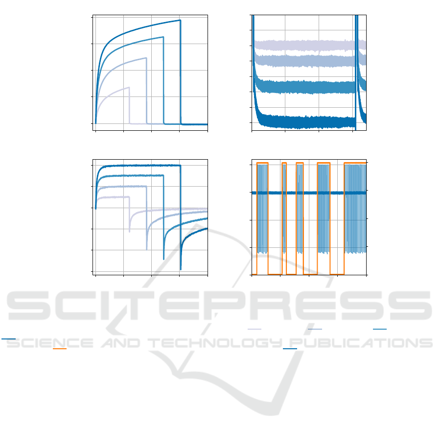
3.2.2 Results
The voltage recordings in Fig. 4(a) exhibited the
characteristic waveform associated with current-
controlled stimulation. The voltage increases rapidly
initially, representing the voltage drop across the
electrolyte resistance, and is followed by the volt-
age drop across the electrode-electrolyte interface
(Boehler et al., 2020). No offset voltage can be ob-
served in the volt range. Only a closer examination in
the millivolt range reveals its presence (see Fig. 4(c)).
The current recordings in Fig. 4(b) demonstrated
sharp rising and falling edges, as well as a precise
constant current throughout the pulse width across all
settings. The end of each pulse is followed by the re-
versal pulse that results from shorting the electrode
to ground. Without the use of an additional resis-
tor in the discharge path, the reversal pulses show
peak values that have slightly higher magnitudes than
the stimulation current, with a maximum of approx.
100 µA. After the peak, the current drops exponen-
tially, with the double-layer capacitor almost com-
pletely discharged after five time constants, which
are reached in less than one millisecond for all set-
tings. For typical stimulation frequencies, this short
discharge time enables the use of a resistance in the
discharge path in order to reduce the peak value of
the reversal pulse to at least the same magnitude as
the stimulation current, a value commonly used in ac-
tive charge balancing (symmetric biphasic) (Parastar-
feizabadi and Kouzani, 2017).
The voltage recordings presented in Fig. 4(c) in-
dicate the offset voltage caused by the blocking ca-
pacitor. After the start of stimulation, the offset volt-
age shifted towards more negative values over time
and the observations were continued until stabiliza-
tion, which occurred after approximately 5 minutes.
The figure shows the offset voltage in the steady state
between two DBS pulses for each stimulation param-
eter setting. This offset can be approximated as con-
sistent DC bias, as the DBS pulse is short relative to
the pulse-off phase and the offset voltage reaches its
value rapidly after the DBS pulse. Furthermore, the
figure shows that the magnitude of the offset voltage
increases with higher injected charge, which is ex-
plained in (van Dongen and Serdijn, 2016). For the
50 µA/60 µs pulse, the offset voltage is recorded as
the smallest negative value at −25 mV, whereas the
200 µA/150 µs pulse results in the most negative off-
set voltage of −70 mV. Considering the theoretical
minimum potential difference of 1.23 V needed for
water splitting (Lamy and Millet, 2020) as the critical
limit for the developed DC bias absolute value, the
measured offset voltages are significantly lower for
all settings. This high safety margin is achieved by
the integrated 10 MΩ resistor in parallel to the load,
which provides an effective discharge path for the im-
balanced charge.
The Fig. 4(d) presents a randomly timed DBS on-
off scheme. The stimulation pulses show a precise
stimulation current of 100 µA, accompanied by the
reversal pulses resulting from the charge balancing
method. The on-off pattern is achieved by toggling
the enable signal (EN
Ch1(H)
) at the input of the AND
gate of the first channel. Moreover, the enable sig-
nal switches between 0 V and 4 V, demonstrating the
proper functioning of the level translation (see Sec-
tion 2.3.4). The measurements show that STELLA
+
effectively enables the implementation of this aDBS
control option.
3.3 Current Consumption vs.
Compliance Voltage
The compliance voltage and corresponding current
consumption are important performance metrics for a
neurostimulator that delivers current-controlled stim-
ulation pulses. To investigate this relationship for
STELLA
+
, the following measurement setup was de-
signed.
3.3.1 Measurement Setup
The current waveform analyzer CX3324A was
placed in series with an external power supply and
STELLA
+
. The power supply was set to 3.7 V, which
is the nominal voltage of the A4X series. The current
consumption was then measured for the supply volt-
age at a minimum of 2.5 V and a maximum of 5.2 V
provided by the buck-boost topology. The CX3324A
STELLA+: Expanding the Research Potential for Long-Term Deep Brain Stimulation Studies in Freely-Moving Rodents
81
0 50 100 150 200
Time (µs)
0
1
2
3
4
Voltage (V)
0.0 2.5 5.0 7.5
Time (ms)
0
-10
-20
-30
-40
-50
-60
-70
Voltage (mV)
0 50 100 150 200
Time (µs)
−300
−200
−100
0
100
200
Current (µA)
0.0 0.2 0.4 0.6 0.8
Time (s)
−300
−200
−100
0
100
Current (µA)
0
1
2
3
4
Voltage (V)
(a)
(b)
(c)
(d)
Figure 4: Performance of STELLA
+
in delivering current-controlled stimulation pulses via a bipolar PI-SNEX-100 immersed
in a 0.199 S m
−1
saline solution. The figure illustrates recordings of (a) voltage and (b) current of the DBS pulse, as well as
(c) the offset voltage in steady state at various stimulation parameters: 50 µA/60 µs, 100 µA/90 µs, 150 µA/120 µs,
200 µA/150 µs, all at a frequency of 130 Hz. Additionally, (d) a randomly timed DBS on-off scheme controlled by the
enable signal ( ) is shown, with stimulation set to 100 µA, 60 µs and 130 Hz ( ).
sampled the current at 1 MSa/s and the final result
was calculated by averaging the measurement over
a period of 20 s. Furthermore, both measurements
were performed in DBS-on mode, using the follow-
ing stimulation parameters: bilateral stimulation with
a load of 10 kΩ respectively, 100 µA current ampli-
tude, 60 µs pulse width and 130 Hz frequency. Finally,
the compliance voltage was determined as the voltage
at which the adjusted constant current started to drop,
which was observed with an oscilloscope. This was
typically noticed when the voltage of the DBS pulse
exceeded the level that was 0.9 V lower than the cur-
rent source’s supply voltage.
3.3.2 Results
STELLA
+
achieves at its minimum compliance volt-
age of 1.6 V a current consumption of 8.9 µA and at
its maximum compliance voltage of 4.3 V a current
consumption of 25.1 µA. In comparison, the previ-
ous STELLA version achieved a maximum compli-
ance voltage of 2.8 V with 12.2 µA.
The results show that STELLA
+
provides a higher
compliance voltage than its predecessor, enabling a
wider range of stimulation setups while still main-
taining an ultra-low current consumption for long-
term studies. When the maximum compliance volt-
age is required, STELLA
+
still provides 6.8 weeks of
stimulation using the CP9440 A4X battery (29 mAh),
which is sufficient for most rodent DBS studies.
3.4 Comparison of Features with the
State-of-the-Art
To compare the results with other DBS devices de-
signed for rodent studies, a review of the relevant lit-
erature was conducted. ASIC designs were excluded
from the comparison due to their specialized and pro-
prietary nature, e.g. (Arfin et al., 2009). In contrast,
DBS devices using off-the-shelf discrete components
allow the research community to replicate the designs
and customize them to their experimental needs.
Table 1 presents the feature set of existing ro-
dent DBS devices, organized by publication year
BIODEVICES 2025 - 18th International Conference on Biomedical Electronics and Devices
82

Table 1: Comparison of key features in existing rodent DBS devices designed with off-the-shelf components.
DBS
device
PCB Volume
category
Device
control
Data output
technology
Provided device/
physiological data
Device
Mounting
Stimulation
properties
Extra
features
Radio frequency (RF)
Reed switch/Magnetic sensors
Physical switch/potentiometer
Optical
Radio frequency (RF)
Optical
High-accuracy temperature
3-axis acceleration
Local field potentials (LFPs)
Load impedance (OOR )
Battery voltage (OOR )
Stimulation on/off
Stimulation protocol
Head
Back
Implant
Dual-channel
Current-controlled
Voltage-controlled
Charge-balanced
Adaptive DBS capabilities
SW-adjustable stim. parameters
Auto-set compliance voltage
On-board battery recharge
Battery-powered
STELLA+ L - - - - -
Grotemeyer2024 VL - - - - - - - - - - - - G# - - - - -
STELLA2021 VL - - - - - - - - - - - - -
Tala2021 H - - - - - - - - - - - - - - -
Fleischer2020 VL - - - - - - - - - - - - - - - - -
Adams2019 M - - - - - - - - - - - - - - - -
Alpaugh2019 M - - - - - - - - - - - - - - - - G# - -
Schulz2019 M - - - - - - - - - - - - - - G# -
Pinnell2018 L - - - - - - - - - - - - - G# - -
Fluri2017 M - - - - - - - - - - - - - - - -
Liu2017 M - - - - - - - - - - - G# - - G# - -
Kouzani2017 L - - - - - - - - - - - - - - - G# - -
Parastarfeizabadi2016 VL - - - - - - - G# - - - - - - - - G# - -
K
¨
olbl2016 L - - - - - - - - - - - - - - - G# - - - -
Pinnell2015 M - - - - - - - - - - - - - - -
Acosta2015 VL - - - - - - - - - - - - - - - - - -
Hentall2013 L - - - - - - - - - - - - - - - - -
Ewing2013 M - - - - - - - - - - - - - - -
Haas2012 L - - - - - - - - - - - - G# - - G# - -
Forni2012 L - - - - - - - - - - - - - - - - - - - G# - -
Harnack2008 M - - - - - - - - - - - - - - G# - -
Battery-free (Wireless power transfer)
Burton2021 VL - - - - - - - - - - - - - - - - -
Heo2015 M - - - - - - - - - - G# - - - G# - -
Millard2007 L - - - - - - - - - - - - - - - G# - -
= Feature is implemented; G# = Feature is partially implemented; - = Feature is not implemented;
= Out of range indication; = Optical wireless communication provided (for STELLA2021 refer to (Koschay et al., 2022));
= Inadequate current source design (see 2.3.2); = Inadequate dual-channel design (see 2.3.2);
= Constant current adjustment manually via potentiometer; = Partial subcutaneous implant only;
VL: Very Low ( 500 mm
3
), L: Low (500 1000 mm
3
), M: Medium (1000 5000 mm
3
), H: High ( 5000 mm
3
)
and divided into two classes: battery-powered and
battery-free. Battery-powered devices operate by us-
ing batteries, while battery-free devices depend solely
on wireless power transfer (WPT) from an external
source. Note that WPT requires specialized cages that
can lead to unreliable operation if coils are misaligned
due to the animal movement, and prevent essential be-
havioral experiments like the Morris water maze (Mil-
lard and Shepherd, 2007; Burton et al., 2021; Evers
et al., 2022).
The features identified in the literature were orga-
nized into categories, which are analyzed in the fol-
lowing.
PCB Volume Category: The PCB volume is of
crucial importance as it dictates the mounting options
and overall impact on the animal. The DBS devices
were categorized based on their PCB volume into four
classes (see Table 1). In cases where the PCB volume
was not indicated, it was estimated from the photo-
graphic scale. The volume specifications are based
on earlier work and were expanded in this study by
further DBS devices (Plocksties et al., 2021a).
STELLA
+
falls into the ‘low’ category as it has
been specifically designed to allow fully subcuta-
neous implantation in small rodents.
Device Control: Radio frequency communication is
considered the most effective control method as it al-
lows to modify a wide range of device parameters
without disturbing the animal. However, the require-
ment for considerable PCB area, the need for higher
power consumption and the complexity of RF de-
sign have limited its widespread use. The most com-
monly used control method involves magnetic sen-
sors, which are mainly used to trigger specific device
functions, such as integrated self-tests. Some stim-
ulators also incorporate physical elements, including
switches and potentiometers. However, these compo-
nents are large as they have to be operated manually,
STELLA+: Expanding the Research Potential for Long-Term Deep Brain Stimulation Studies in Freely-Moving Rodents
83

leading to a poor functionality-to-size ratio. Another
control mechanism involves transmitting light pulses
to a photodiode. However, this approach is challeng-
ing due to the movement of the animals and is cur-
rently only used in one stimulator (Heo et al., 2015).
In contrast, STELLA
+
does not include any opti-
cal or physical elements for its control. Instead, it uses
Bluetooth Low Energy (BLE), which enables detailed
configuration of the device parameters from a great
distance to the animal. To ensure redundancy, the
device includes a magnetic sensor for essential tasks,
like turning the stimulation on/off.
Data Output Technology: RF communication en-
ables high data rates, which are required for the wire-
less transmission of physiological data, such as local
field potentials and accelerometer data. However, due
to the aforementioned obstacles associated with RF
modules, optical data transmission is most commonly
used in DBS devices. For this, LEDs are utilized that
operate either in the visible spectrum or in the infrared
range (IR), with simple blinking patterns indicating
device information, e.g. low battery voltage alerts.
STELLA
+
employs the nRF52833 microcon-
troller, which supports BLE for efficient transmis-
sion of device and physiological data. Additionally,
STELLA
+
features two visible LEDs (red and green)
and an IR LED for convenient indication of device
information.
Provided Device/Physiological Data: Most DBS
devices provide only basic device-specific data, such
as low battery voltage alerts and the stimulation status
(on/off). However, the indication of out-of-range load
impedance is rarely provided, despite its significance
for replicable experiments. In addition, only two DBS
devices allow the transmission of the applied stimu-
lation protocol, which is important for verifying that
the stimulation parameters are set correctly, especially
when they have been changed. Moreover, only one
device is able to transmit physiological data wire-
lessly, specifically local field potentials (LFPs) (Pin-
nell et al., 2015). The other device that enables the
readout of LFPs, processes this data entirely on-board
(Parastarfeizabadi et al., 2016).
STELLA
+
is the first DBS device for rodents that
incorporates a high-accuracy temperature sensor and
a 3-axis accelerometer. The accelerometer enables the
investigation of movement profiles, which could rep-
resent a potential biomarker for adaptive DBS, while
requiring significantly less PCB area and energy com-
pared to traditional LFP recordings. Additionally,
STELLA
+
provides data on the battery voltage, the
on/off status of the stimulation, the applied stimu-
lation protocol, and whether the load impedance is
within a valid range. All device and physiological
data can be transmitted wirelessly via BLE.
Device Mounting: Most DBS devices are designed
for head or backpack mounting, which limits animal
mobility and often leads to higher failure rates. Fully
implantable stimulators overcome these problems, but
are more challenging to realize due to their high de-
gree of miniaturization and waterproof encapsulation.
STELLA
+
is characterized by a small stimulator-
battery volume, making it ideal for subcutaneous im-
plantation in small rodents. Its flat profile also sup-
ports the healing process by reducing tension on the
overlying skin.
Stimulation Properties: Most DBS devices are
primarily designed with charge-balanced current-
controlled stimulation, while voltage-controlled stim-
ulation is rarely implemented. Furthermore, the ma-
jority of DBS devices are designed for single-channel
stimulation, which limits DBS to one hemisphere. A
dual-channel design is less common, although a sec-
ond channel is essential for studying bilateral DBS.
In contrast, STELLA
+
provides the ability to se-
lect between charge-balanced current-controlled and
charge-balanced voltage-controlled stimulation for
one or two channels. Moreover, STELLA
+
features
aDBS capabilities through on-off switching of stim-
ulation based on feedback data from a 3-axis ac-
celerometer. This functionality is only supported by
two other stimulators, which differ in that they use
LFPs as feedback data (Pinnell et al., 2015; Paras-
tarfeizabadi et al., 2016). Additionally, STELLA
+
includes a powerful processing core that enables on-
board processing capabilities for complex algorithms.
Extra Features: DBS devices often provide the extra
feature of adjusting the stimulation parameters cur-
rent amplitude, frequency and pulse width via soft-
ware. In cases where this feature is only partially
available, the adjustment of the current amplitude is
typically limited to the use of an analog potentiome-
ter or the resoldering of a resistor.
With STELLA
+
, all stimulation parameters can
be configured via software and also adjusted wire-
lessly via BLE during the experiment. Additionally,
the automatic adjustment of the compliance voltage
improves energy efficiency and is exclusive to both
STELLA
+
and its predecessor. Finally, STELLA
+
supports on-board battery recharging via electrode
leads, an extra feature that is also present in only one
other DBS device via wireless power transfer.
In summary, it can be concluded from Table 1
that STELLA
+
has a wider and unique feature set
compared with other state-of-the-art DBS devices for
rodent DBS.
BIODEVICES 2025 - 18th International Conference on Biomedical Electronics and Devices
84

4 CONCLUSION
We introduce STELLA
+
, an innovative research plat-
form designed for advanced DBS studies in freely-
moving rodents. This paper serves as a starting point
for future in vivo DBS studies in rodents and primar-
ily focuses on the specifications and capabilities of
STELLA
+
. The initial results highlight STELLA
+
’s
compact design, energy-efficient architecture, inte-
grated system monitoring and accurate generation of
current-controlled and charge-balanced DBS pulses,
which together form the basis for effective preclini-
cal DBS research. Equipped with multiple sensors,
a powerful processing unit and a Bluetooth Low En-
ergy module, STELLA
+
enables research into closed-
loop stimulation. Compared to its predecessor and
other state-of-the-art DBS devices, STELLA
+
offers
unprecedented experimental flexibility (see Table 1),
rendering it an essential tool for both traditional and
adaptive DBS research in rodents.
ACKNOWLEDGMENT
Funded by the Deutsche Forschungsgemeinschaft
(DFG, German Research Foundation) - SFB 1270/1,2
- 299150580. Our special thanks go to VARTA for
providing Li-ion button cells for research purposes
and to Uwe Kn
¨
upfer for his manufacturing support.
REFERENCES
Adams, S. D., Bennet, K. E., Tye, S. J., Berk, M.,
and Kouzani, A. Z. (2019). Development of a
miniature device for emerging deep brain stimulation
paradigms. PLOS ONE, 14(2):e0212554.
Akhtari, M., Salamon, N., Duncan, R., Fried, I., and Math-
ern, G. (2006). Electrical conductivities of the freshly
excised cerebral cortex in epilepsy surgery patients;
correlation with pathology, seizure duration, and dif-
fusion tensor imaging. Brain Topography, 18:281–
290.
Arfin, S. K., Long, M. A., Fee, M. S., and Sarpeshkar,
R. (2009). Wireless neural stimulation in freely be-
having small animals. Journal of neurophysiology,
102(1):598–605.
Badstuebner, K., Gimsa, U., Weber, I., Tuchscherer, A., and
Gimsa, J. (2017). Deep brain stimulation of hemi-
parkinsonian rats with unipolar and bipolar electrodes
for up to 6 weeks: Behavioral testing of freely moving
animals. Parkinson's Disease, 2017:1–18.
Boehler, C., Carli, S., Fadiga, L., Stieglitz, T., and As-
plund, M. (2020). Tutorial: guidelines for standard-
ized performance tests for electrodes intended for neu-
ral interfaces and bioelectronics. Nature protocols,
15(11):3557–3578.
Burton, A., Won, S. M., Sohrabi, A. K., Stuart, T., Amirhos-
sein, A., Kim, J. U., Park, Y., Gabros, A., Rogers,
J. A., Vitale, F., et al. (2021). Wireless, battery-free,
and fully implantable electrical neurostimulation in
freely moving rodents. Microsystems & nanoengi-
neering, 7(1):62.
de Haas, R., Struikmans, R., van der Plasse, G., van
Kerkhof, L., Brakkee, J. H., Kas, M. J., and West-
enberg, H. G. (2012). Wireless implantable micro-
stimulation device for high frequency bilateral deep
brain stimulation in freely moving mice. Journal of
neuroscience methods, 209(1):113–119.
D
´
ıez-Solinska, A., Vegas, O., and Azkona, G. (2022). Re-
finement in the european union: a systematic review.
Animals, 12(23):3263.
Evers, J., Orłowski, J., Jahns, H., and Lowery, M. M.
(2024). On-off and proportional closed-loop adaptive
deep brain stimulation reduces motor symptoms in
freely moving hemiparkinsonian rats. Neuromodula-
tion: Technology at the Neural Interface, 27(3):476–
488.
Evers, J., Sridhar, K., Liegey, J., Brady, J., Jahns, H., and
Lowery, M. (2022). Stimulation-induced changes at
the electrode–tissue interface and their influence on
deep brain stimulation. Journal of Neural Engineer-
ing, 19(4):046004.
Ewing, S. G., Lipski, W. J., Grace, A. A., and Winter,
C. (2013). An inexpensive, charge-balanced rodent
deep brain stimulation device: A step-by-step guide
to its procurement and construction. Journal of Neu-
roscience Methods, 219(2):324–330.
Fleischer, M., Endres, H., Sendtner, M., and Volkmann, J.
(2020). Development of a fully implantable stimula-
tor for deep brain stimulation in mice. Frontiers in
Neuroscience, 14.
Fluri, F., M
¨
utzel, T., Schuhmann, M. K., Krsti
´
c, M., En-
dres, H., and Volkmann, J. (2017). Development of a
head-mounted wireless microstimulator for deep brain
stimulation in rats. Journal of Neuroscience Methods,
291:249–256.
Forni, C., Mainard, O., Melon, C., Goguenheim, D., Goff,
L. K.-L., and Salin, P. (2012). Portable microstimula-
tor for chronic deep brain stimulation in freely moving
rats. Journal of Neuroscience Methods, 209(1):50–57.
Gabriel, C. and Gabriel, S. (1996). Compilation of the di-
electric properties of body tissues at rf and microwave
frequencies.
Gimsa, J., Habel, B., Schreiber, U., van Rienen, U., Strauss,
U., and Gimsa, U. (2005). Choosing electrodes for
deep brain stimulation experiments–electrochemical
considerations. Journal of Neuroscience Methods,
142(2):251–265.
Grotemeyer, A., Petschner, T., Peach, R., Hoehl, D.,
Knauer, T., Thomas, U., Endres, H., Blum, R., Sendt-
ner, M., Volkmann, J., and Ip, C. W. (2024). Standard-
ized wireless deep brain stimulation system for mice.
npj Parkinson’s Disease, 10(1).
STELLA+: Expanding the Research Potential for Long-Term Deep Brain Stimulation Studies in Freely-Moving Rodents
85

Hamani, C. and N
´
obrega, J. N. (2010). Deep brain stimula-
tion in clinical trials and animal models of depression.
European Journal of Neuroscience, 32(7):1109–1117.
Harmsen, I. E., Elias, G. J., Beyn, M. E., Boutet, A., Pan-
choli, A., Germann, J., Mansouri, A., Lozano, C. S.,
and Lozano, A. M. (2020). Clinical trials for deep
brain stimulation: Current state of affairs. Brain Stim-
ulation, 13(2):378–385.
Hasgall, P., Di Gennaro, F., Baumgartner, C., Neufeld, E.,
Lloyd, B., Gosselin, M., Payne, D., Klingenb
¨
ock, A.,
and Kuster, N. (2022). It’is database for thermal and
electromagnetic parameters of biological tissues, ver-
sion 4.1.
Heerdegen, M., Zwar, M., Franz, D., H
¨
ornschemeyer, M. F.,
Neubert, V., Plocksties, F., Niemann, C., Timmer-
mann, D., Bahls, C., van Rienen, U., et al. (2021).
Mechanisms of pallidal deep brain stimulation: Al-
teration of cortico-striatal synaptic communication in
a dystonia animal model. Neurobiology of Disease,
154:105341.
Heo, M. S., Moon, H. S., Kim, H. C., Park, H. W., Lim,
Y. H., and Paek, S. H. (2015). Fully implantable deep
brain stimulation system with wireless power trans-
mission for long-term use in rodent models of parkin-
son’s disease. Journal of Korean Neurosurgical Soci-
ety, 57(3):152–158.
Huang, C. Q., Carter, P. M., and Shepherd, R. K. (2001).
Stimulus induced ph changes in cochlear implants: an
in vitro and in vivo study. Annals of biomedical engi-
neering, 29:791–802.
Hui, D., Murgai, A. A., Gilmore, G., Mohideen, S. I., Par-
rent, A. G., and Jog, M. S. (2020). Assessing the effect
of current steering on the total electrical energy deliv-
ered and ambulation in parkinson’s disease. Scientific
Reports, 10(1):8256.
Jakobs, M., Fomenko, A., Lozano, A. M., and Kiening,
K. L. (2019). Cellular, molecular, and clinical mech-
anisms of action of deep brain stimulation—a sys-
tematic review on established indications and outlook
on future developments. EMBO molecular medicine,
11(4):e9575.
Kandadai, R. M., Meka, S. S., Kola, S., Alugolu, R., and
Borgohain, R. (2023). Constant current versus con-
stant voltage dbs stimulators—changing trend. Annals
of Indian Academy of Neurology, 26(4):368–369.
Klinder, A., Moews, F., Ziebart, J., Su, Y., Gabler, C.,
Jonitz-Heincke, A., van Rienen, U., Ellenrieder, M.,
and Bader, R. (2024). Effects of electrical stim-
ulation with alternating fields on the osseointegra-
tion of titanium implants in the rabbit tibia-a pilot
study. Frontiers in Bioengineering and Biotechnol-
ogy, 12:1395715.
Koessler, L., Colnat-Coulbois, S., Cecchin, T., Hofmanis,
J., Dmochowski, J. P., Norcia, A. M., and Maillard,
L. G. (2017). In-vivo measurements of human brain
tissue conductivity using focal electrical current in-
jection through intracerebral multicontact electrodes.
Human brain mapping, 38(2):974–986.
Koschay, M., Richter, H., Statz, M., Kober, M., Puschmann,
J., Plocksties, F., Storch, A., K
¨
uhn, V., and Timmer-
mann, D. (2022). Case-study on visible light com-
munication for implant monitoring. In 2022 IEEE
Biomedical Circuits and Systems Conference (Bio-
CAS), pages 275–279. IEEE.
Kouzani, A. Z., Kale, R. P., Zarate-Garza, P. P., Berk,
M., Walder, K., and Tye, S. J. (2017). Validation of
a portable low-power deep brain stimulation device
through anxiolytic effects in a laboratory rat model.
IEEE Transactions on Neural Systems and Rehabili-
tation Engineering, 25(9):1365–1374.
K
¨
olbl, F., N’Kaoua, G., Naudet, F., Berthier, F., Fag-
giani, E., Renaud, S., Benazzouz, A., and Lewis,
N. (2016). An embedded deep brain stimulator for
biphasic chronic experiments in freely moving ro-
dents. IEEE Transactions on Biomedical Circuits and
Systems, 10(1):72–84.
Lamy, C. and Millet, P. (2020). A critical review on the def-
initions used to calculate the energy efficiency coeffi-
cients of water electrolysis cells working under near
ambient temperature conditions. Journal of power
sources, 447:227350.
Leblois, A., Reese, R., Labarre, D., Hamann, M., Richter,
A., Boraud, T., and Meissner, W. G. (2010). Deep
brain stimulation changes basal ganglia output nuclei
firing pattern in the dystonic hamster. Neurobiology of
disease, 38(2):288–298.
Lempka, S. F., Johnson, M. D., Miocinovic, S., Vitek, J. L.,
and McIntyre, C. C. (2010). Current-controlled deep
brain stimulation reduces in vivo voltage fluctuations
observed during voltage-controlled stimulation. Clin-
ical Neurophysiology, 121(12):2128–2133.
Lempka, S. F., Miocinovic, S., Johnson, M. D., Vitek, J. L.,
and McIntyre, C. C. (2009). In vivo impedance spec-
troscopy of deep brain stimulation electrodes. Journal
of neural engineering, 6(4):046001.
Liu, H., Wang, C., Zhang, F., and Jia, H. (2017). An im-
plantable device for neuropsychiatric rehabilitation by
chronic deep brain stimulation in freely moving rats.
NeuroReport, 28(3):128–133.
Merrill, D. R., Bikson, M., and Jefferys, J. G. (2005). Elec-
trical stimulation of excitable tissue: design of effi-
cacious and safe protocols. Journal of neuroscience
methods, 141(2):171–198.
Millard, R. E. and Shepherd, R. K. (2007). A fully im-
plantable stimulator for use in small laboratory ani-
mals. Journal of neuroscience methods, 166(2):168–
177.
Neumann, W.-J., Gilron, R., Little, S., and Tinkhauser, G.
(2023). Adaptive deep brain stimulation: From ex-
perimental evidence toward practical implementation.
Movement disorders, 38(6):937–948.
Nicksic, P. J., Donnelly, D. T., Verma, N., Setiz, A. J.,
Shoffstall, A. J., Ludwig, K. A., Dingle, A. M., and
Poore, S. O. (2022). Electrical stimulation of acute
fractures: A narrative review of stimulation protocols
and device specifications. Frontiers in Bioengineering
and Biotechnology, 10:879187.
Paap, M., Perl, S., L
¨
uttig, A., Plocksties, F., Niemann, C.,
Timmermann, D., Bahls, C., van Rienen, U., Franz,
D., Zwar, M., Rohde, M., K
¨
ohling, R., and Richter,
A. (2021). Deep brain stimulation by optimized stim-
ulators in a phenotypic model of dystonia: Effects
BIODEVICES 2025 - 18th International Conference on Biomedical Electronics and Devices
86

of different frequencies. Neurobiology of Disease,
147:105163.
Parastarfeizabadi, M. and Kouzani, A. Z. (2017). Advances
in closed-loop deep brain stimulation devices. Journal
of neuroengineering and rehabilitation, 14:1–20.
Parastarfeizabadi, M., Kouzani, A. Z., Gibson, I., and Tye,
S. J. (2016). A miniature closed-loop deep brain stim-
ulation device. In 2016 38th Annual International
Conference of the IEEE Engineering in Medicine and
Biology Society (EMBC), pages 1786–1789. IEEE.
Payonk, J. P., Bathel, H., Arbeiter, N., Kober, M., Fauser,
M., Storch, A., van Rienen, U., and Zimmermann,
J. (2025). Improving computational models of deep
brain stimulation through experimental calibration.
Journal of neuroscience methods, 414:110320.
Pinnell, R., Dempster, J., and Pratt, J. (2015). Miniature
wireless recording and stimulation system for rodent
behavioural testing. Journal of neural engineering,
12(6):066015.
Pinnell, R. C., de Vasconcelos, A. P., Cassel, J. C., and Hof-
mann, U. G. (2018). A miniaturized, programmable
deep-brain stimulator for group-housing and water
maze use. Frontiers in Neuroscience, 12.
Plocksties, F., Kober, M., Niemann, C., Heller, J., Fauser,
M., N
¨
ussel, M., Uster, F., Franz, D., Zwar, M.,
L
¨
uttig, A., Kr
¨
oger, J., Harloff, J., Schulz, A., Richter,
A., K
¨
ohling, R., Timmermann, D., and Storch, A.
(2021a). The software defined implantable modular
platform (STELLA) for preclinical deep brain stim-
ulation research in rodents. Journal of Neural Engi-
neering, 18(5):056032.
Plocksties, F., L
¨
uttig, A., Niemann, C., Uster, F., Franz,
D., Kober, M., Koschay, M., Perl, S., Richter, A.,
K
¨
ohling, R., et al. (2022). Strategies on deep brain
stimulation devices for effective behavioral studies in
rodents. In 2022 IEEE-EMBS Conference on Biomed-
ical Engineering and Sciences (IECBES), pages 376–
381. IEEE.
Plocksties, F., Shah, O. U., Uster, F., Ali, M., Koschay, M.,
Kober, M., Storch, A., and Timmermann, D. (2021b).
Energy-efficient modular RF interface for fully im-
plantable electrical devices in small rodents. In 2021
IEEE Biomedical Circuits and Systems Conference
(BioCAS). IEEE.
Raben, H., K
¨
ammerer, P. W., and van Rienen, U. (2024).
Addressing model uncertainties in finite element sim-
ulation of electrically stimulated implants for critical-
size mandibular defects. IEEE Transactions on
Biomedical Engineering.
Reese, R., Charron, G., Nadjar, A., Aubert, I., Thiolat, M.-
L., Hamann, M., Richter, A., Bezard, E., and Meiss-
ner, W. G. (2009). High frequency stimulation of the
entopeduncular nucleus sets the cortico-basal ganglia
network to a new functional state in the dystonic ham-
ster. Neurobiology of disease, 35(3):399–405.
Ruiz, M. C. M., Guimar
˜
aes, R. P., and Mortari, M. R.
(2022). Parkinson’s disease rodent models: Are they
suitable for dbs research? Journal of Neuroscience
Methods, 380:109687.
Statz, M., Kober, M., Schleuter, F., Bathel, H., Plocksties,
F., Timmermann, D., van Rienen, U., Fauser, M., and
Storch, A. (2023a). Effects of deep brain stimulation
in the subthalamic nucleus (stn-dbs) on cellular plas-
ticity in catecholaminergic systems in a hemiparkin-
sonian rat model. Brain Stimulation: Basic, Trans-
lational, and Clinical Research in Neuromodulation,
16(1):313–314.
Statz, M., Schleuter, F., Weber, H., Kober, M., Plock-
sties, F., Timmermann, D., Storch, A., and Fauser, M.
(2023b). Subthalamic nucleus deep brain stimulation
does not alter growth factor expression in a rat model
of stable dopaminergic deficiency. Neuroscience Let-
ters, 814:137459.
Ungerstedt, U. (1968). 6-hydroxy-dopamine induced de-
generation of central monoamine neurons. European
journal of pharmacology, 5(1):107–110.
van Dongen, M. N. and Serdijn, W. A. (2016). Does a
coupling capacitor enhance the charge balance during
neural stimulation? an empirical study. Medical &
biological engineering & computing, 54:93–101.
VARTA (2019). Technical Handbook CoinPower - Rechar-
gable Li-Ion Button Cells Generation A4. version 1.0.
Zhang, K. K., Matin, R., Gorodetsky, C., Ibrahim, G. M.,
and Gouveia, F. V. (2024). Systematic review of ro-
dent studies of deep brain stimulation for the treatment
of neurological, developmental and neuropsychiatric
disorders. Translational Psychiatry, 14(1):186.
STELLA+: Expanding the Research Potential for Long-Term Deep Brain Stimulation Studies in Freely-Moving Rodents
87
