
Grid Interactive Smart Buildings Coordination in Multi-Area Power
Systems: A Delay-Robustness Analysis
Amedeo Andreotti
a
, Bianca Caiazzo
b
, Sara Leccese
c
, Alberto Petrillo
d
, Lorenzo Redi and
Stefania Santini
e
University of Naples Federico II, Italy
{amedeo.andreotti, bianca.caiazzo, sara.leccese, alberto.petrillo, lorenzo.redi, stefania.santini}@unina.it
Keywords:
Distributed Control, Grid-Interactive Smart Buildings, Delay Robustness, Frequency Regulation, Demand
Response.
Abstract:
This work focuses on the frequency support control problem for Grid-Interactive Smart Buildings (GISBs)
with Thermostatically-Controlled Loads (TCLs). The problem is formalized by leveraging multi-agent sys-
tems paradigm and a distributed delayed PID-based controller is introduced in order to guarantee that each
GISB provides a fast frequency support to the main grid while maintaining a desired comfort level. Compared
to the technical literature, the main novelty relies in considering communication latencies from the begin-
ning of control design phase, thus guaranteeing that the proposed control protocol is able to counteract the
unavoidable presence of heterogeneous time-varying delays arising during information sharing among all the
electrical entities. Extensive simulation results, exploiting also latin hypercube sampling technique, show the
effectiveness and the resilience of the approach with respect to delays and parameters uncertainties, while also
highlighting the delay stability margin of the entire network.
1 INTRODUCTION
The rapid integration of Renewable Energy Sources
(RESs), such as photovoltaic and wind power, has
significantly changed the nature of power systems
(Wang et al., 2019b; Duan et al., 2022). Although
these greener resources promote a cleaner energy mix
(Xia et al., 2019), they have also introduced crucial
issues related to the stability of power systems. In-
deed, their inherently variable and unpredictable na-
ture can cause frequent and rapid power imbalances.
Moreover, the high level of RESs spread has also sig-
nificantly reduced system inertia by replacing syn-
chronous machines (Zheng et al., 2021), thus increas-
ing both the amplitude and the recurrence of fre-
quency deviations (Zhao et al., 2023). It follows that,
despite their crucial benefits devoted to greener and
cleaner energy systems, RESs may compromise the
overall grid reliability, thus requiring the need of ad-
hoc countermeasures. (Wang et al., 2019b).
a
https://orcid.org/0000-0002-6514-6807
b
https://orcid.org/0000-0002-1676-2814
c
https://orcid.org/0009-0001-8939-1129
d
https://orcid.org/0000-0003-4630-6673
e
https://orcid.org/0000-0002-0754-6271
Paving the way towards innovative and adaptive
strategies able to support frequency recovery while
ensuring the stability of modern power systems is
one of the fundamental issue to be addressed by re-
searchers in the next years. In this direction, there
is a growing interest into the usage of flexible re-
sources from the demand side (Liu et al., 2022), such
as Temperature-Controlled Loads (TCLs), i.e., heat-
ing, ventilation and air-conditioning systems able to
quickly respond to power system variations (Xiao
et al., 2023). Unlike traditional demand response
systems, which often disrupt user activities, TCLs
can also provide grid support while maintaining at
the same time a proper comfort level by means of
predefined temperature ranges. The recent trend
is the evaluation of collective effects provided by
a multiple aggregated TCLs, which leads to the
so-called Grid-Interactive Smart Buildings (GISBs)
paradigm. Specifically, GISBs represent an aggrega-
tion of TCLs, which can be viewed as one single en-
tity from grid perspective able to act as virtual energy
storage and provide timely support to frequency reg-
ulation (Wang et al., 2019b; Wang et al., 2019a).
Centralized solutions have been widely explored
to address coordination control problem of TCLs
(Zhang et al., 2018; Zhao et al., 2016). How-
48
Andreotti, A., Caiazzo, B., Leccese, S., Petrillo, A., Redi, L. and Santini, S.
Grid Interactive Smart Buildings Coordination in Multi-Area Power Systems: A Delay-Robustness Analysis.
DOI: 10.5220/0013357600003953
Paper published under CC license (CC BY-NC-ND 4.0)
In Proceedings of the 14th International Conference on Smart Cities and Green ICT Systems (SMARTGREENS 2025), pages 48-55
ISBN: 978-989-758-751-1; ISSN: 2184-4968
Proceedings Copyright © 2025 by SCITEPRESS – Science and Technology Publications, Lda.

ever, these architectures face some limitations, espe-
cially related to scalability issue and high computa-
tional burdens, which become more crucial as far as
the number of spatially distributed systems increases.
That’s way latest GISB control strategies are moving
towards distributed control solutions, which exploit
Multi-Agent Systems (MASs) modeling approach to
deal with the coordination of multiple TCLs. In
this perspective, each spatially distributed building
is modeled as an agent able to share its own lo-
cal information with the corresponding neighboring
set by means of a communication network in order
to achieve a global coordinated behavior (Ge et al.,
2018). Along this line, a distributed average con-
sensus algorithm has been introduced in (Chen et al.,
2014) to solve the fair power allocation problem in
a TLC aggregator. Authors in (Zheng et al., 2021)
have proposed a distributed control approach for fre-
quency support in aggregated buildings able to bal-
ance their energy level while guaranteeing robust and
reliable operations with a desired comfort level for
the occupants. Moreover, in (Wang et al., 2019a) a
two-layer distributed control protocol accounting for
both the inner and the inter buildings communication
graphs has been designed. Furthermore, in (Wang
et al., 2019b), by the means of double layer control
protocols, authors achieve both fair power allocation
among GISBs and a proper comfort level among all
available TCLs. These control objectives are fulfilled
by means of a distributed sliding mode controller,
which provides also robustness and fast response un-
der varying conditions.
Besides the benefits of distributed control ap-
proaches, the control over communication networks
poses several challenges. Since the information ex-
change among buildings is realized via a wireless
communication network, random delays usually arise.
In this context, each GISB receives information with
different time-varying delays, whose value depends
on the network conditions and the specific commu-
nication channel. It follows that delays may signifi-
cantly affect the aggregator control performance and
compromise frequency support capability. Further-
more, in the worst case, delays may lead to the in-
stability of the overall network (Caiazzo et al., 2022).
Based on the above, one can conclude that delays
should be considered from the beginning in order
to prevent dangerous and undesirable situations, i.e.,
from the control design phase. This implies that the
distributed controller has to be designed and imple-
mented via outdated information, which can be done
by using the time stamp inserted into messages to cor-
rectly correlate the information.
Based on the these considerations, this article
aims at designing a distributed controller for the co-
ordination of a GISBs aggregator able to provide fast
frequency support to the grid in normal operating con-
ditions despite the presence of unavoidable communi-
cation delays. We would like to highlight that, com-
pared with (Wang et al., 2019b), where the simula-
tion campaign has also involved a robustness analy-
sis with respect to constant and homogeneous com-
munication delay, here we allow delays to be time-
varying and heterogeneous for each electrical entity
within the network, while considering them from the
control design phase. We carry out an extensive sim-
ulation campaign in order to derive the delay stability
margin, i.e., the maximum tolerable delay preserving
the stability of the the overall power system. More-
over, to further confirm the effectiveness of the pro-
posed approach, we also employ the Latin Hypercube
Sampling (LHS) method to assess the control perfor-
mance under several parameters and communication
delays uncertainties/variations, as well as for all the
possible combinations of them.
Finally, the paper structure is given as follows.
In Section 2 the problem statement is detailed along
with the modeling of the multi-area power system.
The distributed control protocol for frequency sup-
port problem with heterogeneous time-varying delays
is presented in Section 3, while simulation results are
reported in Section 4. Conclusions are drawn in Sec-
tion 5.
2 PROBLEM FORMULATION
Consider a multi-area power system composed by
M control areas physically interconnected through
tie-lines. Each area k (k = 1, ··· , M) consists of
variable local loads and N
k
GISBs. These latter
are equipped with only air conditioning systems and
share their temperature information with the corre-
sponding neighboring GISBs via a wireless commu-
nication network subject to communication impair-
ments. Thus, the N
k
GISBs in the k-the area act as
a single aggregator for the fast frequency support of
the multi-area power system.
Inspired by (Wang et al., 2019b), the aim of this
work is to design a novel distributed controller for
the GISBs able to guarantee that the whole aggre-
gator provides a fast frequency support to the main
grid −while maintaining its temperature within user-
defined ranges− despite the presence of communica-
tion latencies.
In the sequel we firstly provide the modeling of the
multi-area power system we consider herein.
Grid Interactive Smart Buildings Coordination in Multi-Area Power Systems: A Delay-Robustness Analysis
49

2.1 Network Modeling
The communication among GISBs into the k-the con-
trol area can be modeled as a directed graph G
c
N
k
=
{V
c
N
k
, E
c
N
k
, A
c
k
}, where V
c
N
k
is the set of the N
k
GISBs
and E
c
N
⊆ V
c
N
× V
c
N
stands for the edges set describ-
ing the active communication links. Matrix A
c
k
=
[a
k
i j
] ∈ R
N
k
×N
k
is the adjacency matrix, whose ele-
ments are a
k
i j
= 1 if there exists a link between the
i-th and j-th GISBs, 0 otherwise. Associated to
this graph there is the Laplacian matrix L
k
= [l
k
i j
] ∈
R
N
k
×N
k
such that l
k
ii
=
∑
N
k
j=1
a
k
i j
and l
k
i j
= −a
k
i j
, j ̸= i.
Since we assume also the presence of a virtual build-
ing into the cyber-space imposing the reference be-
havior to the specific k-th control area, it results an
augmented directed graph G
c
N
k
+1
with a Pinning ma-
trix P
k
= diag{p
k
1
, p
k
2
, . . . , p
k
N
k
}, whose elements are
such that p
k
i
= 1 if the leader GISB is directly con-
nected to the i-th GISB, p
k
i
= 0 otherwise. Finally,
the set of neighbors of the i-th GISB is defined as
N
c
i,k
= { j : (i, j) ∈ E
c
N
k
+1
}.
The overall electric topology of the multi-area power
system can be also modeled as a connected weighted
graph G
e
N
= {V
e
N
, E
e
N
, T }, where V
e
N
is the set of
electrical buses connecting the different control areas,
while E
e
N
represents the set of electric power lines.
Furthermore, T is the associated weighted adjacency
matrix, whose elements are such that T
k,ι
= 1 if and
only if there is a tie-line between the area k and area
ι, T
k,ι
= 0 otherwise, for any k, ι ∈ {1, ·· · , M}.
2.2 Multi-Area Power System Model
Here we firstly detail the model of the entire multi-
area power system by means of Load Frequency Con-
trol (LFC) and, then, we move towards the description
of the single GISBs dynamics.
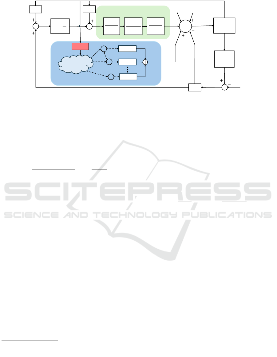
2.2.1 Load Frequency Control
The stability of the overall power system is ensured
via LFC (Wadi et al., 2024), whose objective is to
guarantee that the frequency deviations remain within
an allowable ranges, despite the presence of addi-
tional loads (Yousef et al., 2014). The typical LFC
structure within the single area, reported in Figure
1, allows the physical connection with other differ-
ent control areas, thus automatically balancing and
sharing the load among them. Beside the LFC, we
assume that the power output of the generators is
controlled by their primary and secondary controllers
(Wang et al., 2019b). The relation between power
mismatch and frequency deviation into the k-th area
can be modeled as
∆ f
k
(s) =
1
2H
k
s + D
k
−∆P
L
k
(s) + ∆P
RES
k
(s)
+ M
k
(s)
∆P
c
k
(s) −
1
R
G
k
∆ f
k
(s)
− ∆P
tie
k
(s) + ∆P
agg
k
(s)
!
,
(1)
where ∆ f
k
is the frequency deviation in the k-th con-
trol area, H
k
and D
k
are the load damping and the in-
ertia of the system, respectively, while R
k
stands for
the speed droop coefficient. Furthermore, ∆P
c
k
is the
secondary control input, while ∆P
L
k
, ∆P
RES
k
, ∆P
tie
k
and
∆P
agg
k
are the power variations of loads, RESs, tie-line
and GISBs aggregator, respectively. M
k
denotes the
generators dynamics, which can be expressed as
M
k
(s) =
1
1 + sT
G
k
·
1
1 + sT
T
k
·
1 + sT
CA
k
1 + sT
CB
k
, (2)
where T
G
k
and T
T
k
are the time constants of the gener-
ator and turbine, respectively, while T
CA
k
and T
CB
k
are
the time constants of the transient droop compensator
(Wang et al., 2019b).
The power transfer between the k-th and the ι-th con-
trol areas, k, ι, ∈ {1, . . . , M}, is computed as
∆P
tie
k
(s) =
2π
s
M
∑
ι=1
T
kι
(∆ f
k
(s) − ∆ f
ι
(s)
!
. (3)
According to the technical literature (Wu et al., 2017),
the secondary control input ∆P
c
k
in (1) is usually de-
signed as a PI controller weighing the current value
of the Area Control Error (ACE), whose expression is
derived as
ACE
k
(s) = B
k
∆ f
k
(s) + ∆P
tie
k
(s), (4)
where B
k
is the frequency bias factor of the k-th con-
trol area. Hence, by defining K
p
and K
i
as the pro-
portional and integral gains respectively, the PI-based
secondary controller is provided as follows:
∆P
c
k
(s) =
K
p
+
K
i
s
ACE
k
(s). (5)
However, fast frequency recovery cannot be ensured
by means of the solely secondary control input (5)
(Wang et al., 2019b). Hence, our aim is to adjust the
value of the total power required by the smart build-
ings aggregator, i.e., ∆P
agg
k
(s) in (1), so to make the
frequency recovery faster, which is not possible by
means of (5).
SMARTGREENS 2025 - 14th International Conference on Smart Cities and Green ICT Systems
50
Generator Model
GIBS#1
GIBS#2
GIBS#N
Smart Building Aggregator
GIBS#0
Communication
Network
Figure 1: Overview of the LFC scheme of the k-th area.
2.2.2 Smart Buildings Thermal Dynamic Model
Through this work we assume the i-th smart building
into the k-th area to be equipped with only TCLs, thus
implying that its dynamical behavior can be modeled
by means of its average temperature, i.e., (Wang et al.,
2019b):
C
th
i,k
˙
θ
i,k
(t) =
θ
amb,k
(t) − θ
i,k
(t)
R
th
i,k
− η
i,k
p
i,k
(t)
λ
i,k
+ ω
i,k
(t),
(6)
where θ
i,k
(t) and θ
amb,k
(t) are the internal and am-
bient temperatures, C
th
i,k
and R
th
i,k
are the thermal ca-
pacitance and resistance, respectively, λ
i,k
is the num-
ber of TCLs in the i-th building, p
i,k
(t) represents the
power consumption. Furthermore, η
i,k
is the thermal
coefficient which is defined as η
i,k
> 0 for cooling
TLC and η
i,k
≤ 0 for heating ones. Finally, ω
i,k
(t)
represents a Gaussian disturbance with zero means.
However, in practical applications a GISB has to keep
its temperature within a user-defined range, which
may differ between different buildings. Hence, by
defining this temperature range as [
¯
θ
i,k
− ∆θ
i,k
,
¯
θ
i,k
+
∆θ
i,k
], with
¯
θ
i,k
and ∆θ
i,k
the set-point temperature
and its admissible tolerance, we can introduce an ad-
ditional variable ε
i,k
(t) ∈ [0, 1] standing for the com-
fort level index, i.e.:
ε
i,k
(t) =
θ
i,k
(t) −
¯
θ
i,k
+ ∆θ
i,k
2∆θ
i,k
. (7)
Then, by substituting this latter into (6) and
defining the time-varying disturbance d
i,k
(t) =
θ
amb,k
(t)−
¯
θ
i,k
+∆θ
i,k
+R
th
i,k
ω
i,k
2∆θ
i
C
th
i,k
R
th
i,k
, we obtain:
˙
ε
i,k
(t) =
1
C
th
i,k
R
th
i,k
ε
i,k
(t) −
η
i,k
2∆θ
i,k
C
th
i,k
λ
i
p
i,k
(t) + d
i,k
(t).
(8)
Note that, the comfort level reflects the thermal power
of the i-th building. Specifically, whenever the i-th
GISB reaches its maximum allowable temperature,
then ε
i,k
(t) = 1, meaning that the cooling capacity of
its own TLC cannot be further reduced. On the other
hand, if the comfort level of the i-th GISB is such that
ε
i,k
(t) = 0, it means that it is working at its minimum
allowable temperature and, hence, its cooling capac-
ity cannot be further increased (Wang et al., 2019b).
Following (Wang et al., 2019b), we introduce an aux-
iliary state variable ζ
i,k
(t), whose expression is given
as follows:
ζ
i,k
(t) = a
i,k
ε
i,k
(t) + b
i,k
p
i,k
(t) + d
i,k
(t), (9)
being a
i,k
=
1
C
th
i,k
R
th
i,k
and b
i,k
=
η
i
2∆θ
i,k
C
th
i,k
λ
i,k
. Then, the
comfort level dynamics of the i-th building can be re-
cast as a control-oriented state-space model, i.e.:
˙x
i,k
(t) = A
i,k
x
i,k
(t) + B
i,k
(u
i,k
(t) + d
i,k
(t)), (10)
where x
i,k
(t) = [ε
i,k
(t), ζ
i,k
(t)]
⊤
, u
i,k
(t) = ˙p
i,k
(t) is the
distributed control input to be designed, while A
i,k
and
B
i,k
are defined as:
A
i,k
=
0 1
0 a
i,k
, B
i,k
=
0
b
i,k
. (11)
The amount of power that each building within
the aggregator has to consume to maintain its com-
fort level at a constant reference value
¯
ε
0,k
is defined
as baseline power p
k
b,i
(t), which can be computed as
p
k
b,i
(t) = lim
t→∞
−a
i,k
¯
ε
k
− d
i,k
(t)
b
i,k
. (12)
Thus, the baseline power of the k-th GISBs aggregator
is P
k
b
(t) =
∑
N
k
i=1
p
k
b,i
(t), k ∈ {1, . . . , M}.
Remark 1. Similar to an energy storage system with
dissipation, a GISB maintains its desired temperature
while operating at baseline power. Indeed, when its
power consumption is less then the baseline P
k
b
(t), it
injects power (i.e., discharges) into the grid, whereas
Grid Interactive Smart Buildings Coordination in Multi-Area Power Systems: A Delay-Robustness Analysis
51

whenever its power consumption increases w.r.t. the
baseline, it is able to absorb power (i.e., charge) from
the grid (Wang et al., 2019b). Hence, by controlling
the GISBs aggregator power consumption, i.e. the ref-
erence comfort level, the frequency deviation of the
k-th area can be stabilized.
The control problem addressed through this
manuscript can be formulated as follows.
Problem 1. Consider an energy community of M con-
trol areas physically interconnected via tie-lines, each
of them composed of N
k+1
GISBs sharing informa-
tion via a communication network. Design a dis-
tributed control law able to ensure that all GISBs
within the k-th area, k ∈ {1, . . . , M}, are able to track
the reference behaviour imposed by the correspond-
ing leader x
0,k
(t) = [ε
0,k
(t), ζ
0,k
(t)]
⊤
. This problem
can be mathematically recast as a leader-tracking
consensus, whose control objective is to find u
i,k
(t)
in (10) such that, ∀i = 1, ··· , N
k
,
lim
t→∞
∥x
0,k
(t) − x
i,k
(t)∥ = 0, k ∈ {1, . . . , M}, (13)
despite the presence of unavoidable communications
delays.
3 DISTRIBUTED FREQUENCY
SUPPORT CONTROL WITH
HETEROGENEOUS
TIME-VARYING DELAYS
Before presenting the distributed control protocol we
propose through this work, we firstly detail the leader
behavior within each control area according to the
technical literature (Wang et al., 2019b).
3.1 Leader Control
To solve Problem 1, we assume that, in each area k,
the reference comfort level is provided by a virtual
GISB, labeled with index 0, i.e., x
0,k
(t), whose be-
havior is derived according to (Wang et al., 2019b).
Specifically, based on grid frequency conditions, it
operates in two distinct modes, i.e., i) Frequency Sup-
port Mode (FSM) and ii) Comfort Recovery Mode
(CRM). For sake of clarity, in what follows we pro-
vide a description of both operating modalities.
Frequency Support Mode. FSM is activated when-
ever the system frequency deviations exceed a pre-
defined threshold which denotes a critical imbalance
between power generation and consumption. Under
these conditions, the k-th GISB aggregator provides a
primary frequency support by dynamically adjusting
its power consumption, which can be computed as
P
k
(t) =
N
k
∑
i=1
p
i,k
(t)
=
(
P
k
b
(t) + R
agg,k
(∆ f
M
− ∆ f
k
(t)), ∆ f
k
≥ ∆ f
M
,
P
k
b
(t) + R
agg,k
(∆ f
m
− ∆ f
k
(t)), ∆ f
k
≤ ∆ f
m
,
(14)
where R
agg,k
is the droop gain of the k-th GISB ag-
gregator, while ∆ f
M
and ∆ f
m
stand for the maximum
and the minimum acceptable frequency values. These
latter are usually equal to ∆ f
M
= 0.1 [Hz] and ∆ f
m
=
−0.1[Hz] (Wadi et al., 2024). By virtue of (14), the k-
th leader is able to discharge (charge) power to (from)
the grid during frequency drops (surpluses). In this
operational mode, based on (9) and (14), the behavior
of the k-th leader is described as follows:
(
ε
0,k
(t) =
R
t
0
ζ
0,k
(t)dt
ζ
0,k
(t) =
∑
N
k
i=1
b
i,k
p
i,k
(t)+
∑
N
k
i=1
[a
i,k
ε
i,k
(t)+d
i,k
(t)]
N
k
, ∀k.
(15)
Comfort Recovery Mode. We say that the k-th
GISBs aggregator operates in CRM mode whenever
∆ f
k
∈ [∆ f
m
, ∆ f
M
]. In this case, the temperature of
each smart building involved into the single area con-
trol is kept at a certain value and, hence, the whole
aggregator absorbs an amount of power that is P
k
b
(t).
Thus, the leader behavior x
0,k
(t) = cost with ε
0,k
(t) =
¯
ε
0,k
and ζ
0,k
(t) = 0.
Based on these two operational modes, we finish-
up into a double-layer control architecture for each
control area as in (Wang et al., 2019b), with the first
layer provided by the leader behavior and the second
layer to be designed to satisfy objective (13) in Prob-
lem 1.
3.2 Cooperative Control Protocol for
the GIBS
Here, the objective is to handle Problem 1 arising
in each control area, i.e., to guarantee that all GISB
within the k-th area, k ∈ {1, . . . , M}, track the cor-
responding leader behavior x
0,k
(t). Furthermore, the
distributed control strategy we aim to design has to
counteract the presence of time-varying communica-
tion delays arising during information sharing pro-
cess. For each building i, i = 1, ··· , N
k
, k = 1, . . . , M,
we firstly define the error with respect to the corre-
sponding leader as:
e
i,k
(t) =
e
ε,i,k
(t)
e
ζ,i,k
(t)
=
ε
i,k
(t) − ε
0,k
(t)
ζ
i,k
(t) − ζ
0,k
(t)
. (16)
To deal with Problem 1 we propose the follow-
ing distributed networked PID-based delayed control
SMARTGREENS 2025 - 14th International Conference on Smart Cities and Green ICT Systems
52
strategy:
u
i,k
(t, τ
k
i,k
(t)) =
+k
p
∑
j∈N
c
i
a
k
i j
(e
i,k
(t − τ
k
i,k
(t)) − e
j,k
(t − τ
k
i,k
(t)))
+k
d
∑
j∈N
c
i
a
k
i j
( ˙e
i,k
(t − τ
k
i,k
(t)) − ˙e
j,k
(t − τ
k
i,k
(t))),
+k
i
∑
j∈N
c
i
a
k
i j
Z
t
0
(e
i,k
(s − τ
k
i,k
(s)) − e
j,k
(s − τ
k
i,k
(s)))ds,
(17)
where k
p
, k
d
, k
i
are the proportional, derivative and
integral control gains, respectively, while a
k
i j
mod-
els the communication network topology into the k-th
control area emerging from the presence/absence of
the communication link between i-th and j-th GISB
(see Section 2.1). Furthermore, τ
k
i j
(t) represents the
communication time-varying delays between the i-th
and j-th GISB, for all i, j ∈ V
c
N
k
, which is assumed to
be detectable by timestamp. In doing so, (17) is com-
puted via outdated information, thus preventing any
instability phenomena (Caiazzo et al., 2022).
Assumption 1. (Andreotti et al., 2021) Time-varying
time-delays signals τ
k
i j
(t) are bounded and slowly-
varying, i.e., τ
k
i j
(t) ≤ τ
⋆
and
˙
τ
k
i j
(t) ≤ µ < 1, ∀i, j ∈
V
c
N
k
, ∀k ∈ {1, · ·· , M}.
Remark 2. The stability of the (10) under the ac-
tion of (17) can be proved by means of Lyapunov-
Krasovskii theory for time-delay systems (see, e.g.,
(Andreotti et al., 2021)).
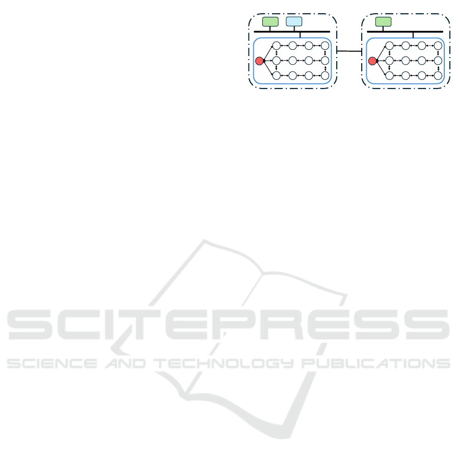
4 NUMERICAL ANALYSIS
In this section we validate the effectiveness of the pro-
posed control (17) in coordinating GISBs aggrega-
tor for fast frequency support despite the presence of
heterogeneous time-varying communication delays.
To this aim, we leverage MATLAB/Simulink simu-
lation platform to emulate a multi-area power system
consisting of M = 2 control areas, each of them in-
cluding an aggregator of N
k
= 12 buildings, k = 1, 2.
Without loss of generality, the LFC parameters in
(1) are assumed to be equal in both control areas
and all the buildings have the same physical char-
acteristics. Communication and electrical topologies
are chosen according to Figure 2, while multi-area
system parameters are chosen according to (Wang
et al., 2019b). From these latter, we have a
i,k
=
−0.25, b
i,k
= −3.125 × 10
−3
, d
i,k
= 0.5625, λ
i,k
=
100, for all i ∈ V
c
N
k
, k = 1, 2. The initial reference
comfort level in each control area provided by the
corresponding virtual GISB during CRM is set as
1 2 3 4
8 7 6 5
9 10 11 12
0
LOAD
GEN
1 2 3 4
8 7 6 5
9 10 11 12
0
GEN
Tie Line
1-2
AREA #1
AREA #2
Figure 2: Communication and electrical topologies of 2-
Area power System.
ε
0,k
(0) =
¯
ε
k
= 50%, while the ambient temperature
is θ
amb,k
= 30[
◦
C], k = 1, 2. This allows computing
the baseline power according to (12), thus obtaining
p
k
i,b
(t) = 1.68 [MW]. A time interval of t = 150 [s] is
considered for validation purpose, where at t = 96 [s]
a load increment of 1.5 [MW] emulates the occurrence
of a contingency within Area #1. In what follows, we
firstly present the worst case scenario, where the max-
imum delay τ
⋆
is chosen as the delay stability mar-
gin preserving the stability. Then, the LHS approach
(Helton and Davis, 2003) is exploited to evaluate the
resilience of the controller (17) w.r.t. different τ
⋆
and
uncertainty range of GISB parameters.
4.1 Worst Case Scenario
In this section we evaluate the robustness of the pro-
posed distributed control in presence of network la-
tencies both in Area #1 and Area #2. The objective is
to find the delay stability margin of the overall system,
i.e., the maximum admissible delay able to preserve
the stability of the entire power system.
To this aim, we carried-out a simulation campaign
where the heterogeneous time-varying delays τ
k
i j
are
emulated as uniformly random variables with a max-
imum value τ
⋆
, which has been iteratively increased
till the stability of the network has been violated. Our
simulation campaign has revealed that the stability of
the multi-area power system we consider is preserved
till τ
⋆
= 0.2 [s], which hence represents our delay sta-
bility margin.
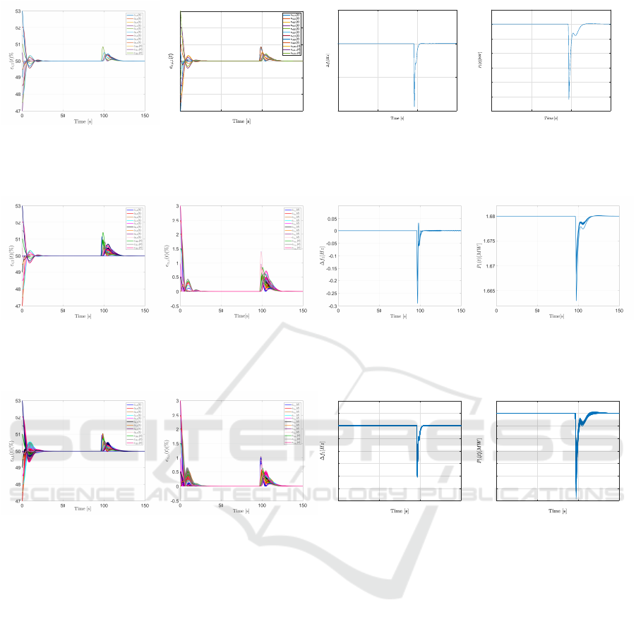
Simulation results achieved in Area #1 in this
worst case scenario are reported in Figure 3. Specifi-
cally, from Figure 3(a) it is possible to appreciate that
our distributed control is able to perform the comfort
recovery of all the GISBs, also after the load chang-
ing occurring at t = 96 [s], with small bounded er-
rors during the transient phases (see Figure 3(b)). In-
deed, at this time instant ∆ f
1
exceeds the minimum
threshold (see Figure 3(c)) and, then, leader behavior
switches to FSM mode according to (14). Then, from
t ∈ [96, 120] [s], the aggregator #1 operates below its
baseline power (see Figure 4(d)), thus discharging
into the grid for primary frequency support. Similar
Grid Interactive Smart Buildings Coordination in Multi-Area Power Systems: A Delay-Robustness Analysis
53
(a)
0 50 100 150
-3
-2
-1
0
1
2
3
(b)
0 50 100 150
-0.2
-0.1
0
0.1
(c)
0 50 100 150
1668
1670
1672
1674
1676
1678
1680
1682
(d)
Figure 3: Distributed frequency support control with heterogeneous time-varying delays with τ
⋆
= 0.2[s]. Time-history of: a)
ε
i,1
(t)[%], i ∈ V
c
N
1
; b) e
ε,i,1
(t)[%], i ∈ V
c
N
1
; c) ∆ f
1
(t)[Hz]; d) P
1
(t) [kW].
(a) (b) (c) (d)
Figure 4: Resilience analysis via LHS method in uncertain delays conditions with τ
⋆
= 0.1[s]. Time-history of: a)
ε
i,1
(t)[%], i ∈ V
c
N
1
; b) e
ε,i,1
(t)[%], i ∈ V
c
N
1
; c) ∆ f
1
(t)[Hz]; d) P
1
(t) [MW ].
(a) (b)
0 50 100 150
-0.3
-0.25
-0.2
-0.15
-0.1
-0.05
0
0.05
(c)
0 50 100 150
1.666
1.668
1.67
1.672
1.674
1.676
1.678
1.68
1.682
(d)
Figure 5: Resilience analysis via LHS method in uncertain GISBs parameters conditions with τ
⋆
= 0.1[s]. Time-history of:
a) ε
i,1
(t)[%], i ∈ V
c
N
1
; b) e
ε,i,1
(t)[%], i ∈ V
c
N
1
; c) ∆ f
1
(t)[Hz]; d) P
1
(t) [MW ].
results are obtained for the Area #2 and, hence, they
are omitted for the sake of brevity.
4.2 Resilience via Latin Hypercube
Sampling Approach
Here we evaluate the robustness and the resilience
of the proposed methodology w.r.t. delay variations
as well as GISBs parameters uncertainties in both
areas. Specifically, we consider two different sce-
narios: a) GISBs parameters assume their nominal
values, while delays variations are considered, i.e.,
τ
k
i j
(t) ∈ [−30%τ
⋆
, +30%τ
⋆
] with τ
⋆
= 0.1 [s]; b) no
delays variations are taken into account, while GISBs
parameters uncertainties are emulated, i.e., the coeffi-
cients of the matrices A
i,k
and B
i,k
in (11) vary within
the range [−20%, +20%] with respect to their nomi-
nal values. To this aim, the LHS approach is exploited
to confirm the resilience of the proposed control strat-
egy under GISB uncertainties and variable commu-
nication time-delays, as well as for all the possible
combinations of them. In both cases, we carried-out a
number of simulations equal to 50.
Results of the two cases a) and b) are reported in
Figures 4-5, which confirm the resilience of the dis-
tributed delayed controller (17) also in these uncertain
conditions.
5 CONCLUSIONS
The paper has addressed the problem of frequency
support for Grid-Interactive Smart Buildings (GISBs)
with Thermostatically-Controlled Loads (TCLs). A
distributed delayed controller has been devised in or-
SMARTGREENS 2025 - 14th International Conference on Smart Cities and Green ICT Systems
54

der to ensure that each GISB provides a fast frequency
support, while counteracting the presence of commu-
nication delays. The delay stability margin has been
found by means of an extensive simulation campaign,
which has also exploited the latin hypercube sampling
technique to prove the resilience of the proposed con-
troller with respect to parameters and delays uncer-
tainties.
REFERENCES
Andreotti, A., Caiazzo, B., Petrillo, A., and Santini,
S. (2021). Distributed robust finite-time secondary
control for stand-alone microgrids with time-varying
communication delays. IEEE Access, 9:59548–
59563.
Caiazzo, B., Lui, D. G., Petrillo, A., and Santini, S. (2022).
Cooperative finite-time control for autonomous ve-
hicles platoons with nonuniform v2v communication
delays. IFAC-PapersOnLine, 55(36):145–150.
Chen, C., Wang, J., and Kishore, S. (2014). A distributed
direct load control approach for large-scale residential
demand response. IEEE Transactions on Power Sys-
tems, 29(5):2219–2228.
Duan, Q., Zeng, K., Liu, J., Du, B., and Liao, P. (2022). Ag-
gregated control of smart building units for frequency
regulation in multi-region power systems. In 2022 7th
Asia Conference on Power and Electrical Engineering
(ACPEE), pages 1209–1214. IEEE.
Ge, X., Han, Q.-L., Ding, D., Zhang, X.-M., and Ning, B.
(2018). A survey on recent advances in distributed
sampled-data cooperative control of multi-agent sys-
tems. Neurocomputing, 275:1684–1701.
Helton, J. C. and Davis, F. J. (2003). Latin hypercube sam-
pling and the propagation of uncertainty in analyses
of complex systems. Reliability Engineering & Sys-
tem Safety, 81(1):23–69.
Liu, X., Li, Y., Lin, X., Guo, J., Shi, Y., and Shen, Y. (2022).
Dynamic bidding strategy for a demand response ag-
gregator in the frequency regulation market. Applied
Energy, 314:118998.
Wadi, M., Shobole, A., Elmasry, W., and Kucuk, I. (2024).
Load frequency control in smart grids: A review of
recent developments. Renewable and Sustainable En-
ergy Reviews, 189:114013.
Wang, Y., Tang, Y., Xu, Y., and Xu, Y. (2019a). A dis-
tributed control scheme of thermostatically controlled
loads for the building-microgrid community. IEEE
Transactions on Sustainable Energy, 11(1):350–360.
Wang, Y., Xu, Y., and Tang, Y. (2019b). Distributed ag-
gregation control of grid-interactive smart buildings
for power system frequency support. Applied energy,
251:113371.
Wu, Y., Wei, Z., Weng, J., Li, X., and Deng, R. H. (2017).
Resonance attacks on load frequency control of smart
grids. IEEE Transactions on Smart Grid, 9(5):4490–
4502.
Xia, M., Song, Y., and Chen, Q. (2019). Hierarchical con-
trol of thermostatically controlled loads oriented smart
buildings. Applied energy, 254:113493.
Xiao, H., Zhang, M., Zeng, L., Wu, G., Wu, C., and Wu,
C. (2023). Hierarchical control strategy of thermo-
statically controlled load considering multiple factors.
Energy and Buildings, 291:113148.
Yousef, H. A., Khalfan, A.-K., Albadi, M. H., and Hossein-
zadeh, N. (2014). Load frequency control of a multi-
area power system: An adaptive fuzzy logic approach.
IEEE transactions on power systems, 29(4):1822–
1830.
Zhang, C., Xu, Y., Li, Z., and Dong, Z. Y. (2018). Ro-
bustly coordinated operation of a multi-energy micro-
grid with flexible electric and thermal loads. IEEE
Transactions on Smart Grid, 10(3):2765–2775.
Zhao, H., Wu, Q., Huang, S., Zhang, H., Liu, Y., and Xue,
Y. (2016). Hierarchical control of thermostatically
controlled loads for primary frequency support. IEEE
Transactions on Smart Grid, 9(4):2986–2998.
Zhao, N., Yue, D., Dou, C., and Shi, T. (2023). Distributed
dynamic event-triggered cooperative control of mul-
tiple tcls and hess for improving frequency regula-
tion. IEEE Transactions on Industrial Informatics,
20(2):1539–1549.
Zheng, L., An, Z., Xia, Q., Kandula, R. P., Saeedifard, M.,
Divan, D., Grijalva, S., and Abdallah, C. T. (2021).
Distributed control of aggregated smart buildings for
frequency regulation. In 2021 IEEE Industry Applica-
tions Society Annual Meeting (IAS), pages 1–8. IEEE.
Grid Interactive Smart Buildings Coordination in Multi-Area Power Systems: A Delay-Robustness Analysis
55
