
Toward Optimized Predictive Maintenance for Vehicle Systems: Deep
Learning-Based Anomaly Detection Using CAN Traffic
Bournane Abbache
1
, Mawloud Omar
2
and Siham Bouchelaghem
2
1
ENSIBS, University of South Brittany, Vannes, France
2
IRISA Laboratory, University of South Brittany, Vannes, France
Keywords:
Predictive Maintenance, LSTM, CAN Data, Multiplexing.
Abstract:
This paper introduces a deep learning-based framework for predictive maintenance in vehicle systems using
Controller Area Network (CAN) traffic data. Modern vehicles rely heavily on electronic components, mak-
ing early fault detection crucial for ensuring safety and reliability. We propose an LSTM-based anomaly
detection model that identifies irregularities in dynamic vehicle parameters, including speed, engine RPM,
steering wheel angle, vehicle suspension height, and headlight position. CAN bus traffic data was metic-
ulously extracted and preprocessed from a real vehicle prototype to train the model, which autonomously
detects anomalies and potential failures. Our experimental results demonstrate the model’s effectiveness in
capturing temporal dependencies within CAN data, enabling precise anomaly detection to support intelligent
predictive maintenance strategies. This proactive approach minimizes downtime, enhances system reliability,
and improves vehicle safety. To foster further research and collaboration, we make the generated dataset pub-
licly available, advancing innovation in vehicle diagnostics and anomaly detection.
1 INTRODUCTION
Modern vehicles rely heavily on electronic systems
to ensure their safety, performance, and efficiency
(Sokolovskij and
ˇ
Zuraulis, 2024). At the core of these
systems lies the Controller Area Network (CAN), a
robust communication protocol designed to facilitate
the exchange of data between various electronic com-
ponents (Rokicki et al., 2020). By reducing the com-
plexity of wiring through multiplexing, the CAN net-
work has become a standard in the automotive in-
dustry, enabling seamless communication among sen-
sors, actuators, and electronic control units (ECUs).
Despite its advantages, the CAN bus is not im-
mune to issues. Equipment malfunctions, such as
wiring faults (e.g., breaks, short circuits, or insulation
failures), can result in incorrect or delayed data trans-
mission. Such anomalies may lead to critical mal-
functions, compromising vehicle safety and perfor-
mance. For instance, erroneous signals processed by
the ECUs could result in incorrect vehicle responses,
such as unintended acceleration or brake failure, pos-
ing significant risks to users.
To address these challenges, predictive mainte-
nance has emerged as a proactive approach to en-
hancing vehicle reliability and safety (Arena et al.,
2021) (Aeddula et al., 2024). By leveraging data-
driven techniques, predictive maintenance identifies
potential failures before they occur, enabling timely
interventions and reducing downtime. Artificial in-
telligence, particularly deep learning, plays a crucial
role by enabling the analysis of complex data of ve-
hicular systems (Johnson et al., 2024). In this direc-
tion, we develop a deep learning-based framework for
predictive maintenance in vehicle systems, focusing
on anomaly detection using CAN bus data. LSTM-
based (Long Short-Term Memory) anomaly detection
is recognized as a promising solution to address this
type of critical system (Lindemann et al., 2021). Our
approach involves developing an LSTM-based model
capable of autonomously identifying irregularities in
CAN traffic, thereby preventing critical failures and
improving vehicle safety. By meticulously collect-
ing and preprocessing data from a real vehicle proto-
type, we aim to demonstrate the effectiveness of our
method in identifying anomalies with the aim to sup-
port the predictive maintenance process.
This paper is structured as follows: Section 2 pro-
vides a detailed overview of the CAN bus architec-
ture, including its multiplexing capabilities, the struc-
ture and format of CAN data frames, and a descrip-
tion of the MT-CAN-LIN-BSI model used in the ex-
418
Abbache, B., Omar, M. and Bouchelaghem, S.
Toward Optimized Predictive Maintenance for Vehicle Systems: Deep Learning-Based Anomaly Detection Using CAN Traffic.
DOI: 10.5220/0013372500003905
In Proceedings of the 14th International Conference on Pattern Recognition Applications and Methods (ICPRAM 2025), pages 418-425
ISBN: 978-989-758-730-6; ISSN: 2184-4313
Copyright © 2025 by Paper published under CC license (CC BY-NC-ND 4.0)
periments. Section 3 outlines the experimental setup,
encompassing the physical configuration, data acqui-
sition process, and preprocessing pipeline necessary
for anomaly detection. Section 4 discusses the results
of the model training and evaluation, highlighting the
performance of the LSTM-based anomaly detection
framework and its ability to capture temporal depen-
dencies in CAN data. Additionally, it provides practi-
cal recommendations for deployment of the proposed
system in real-world vehicle environments. Finally,
section 5 concludes the paper by summarizing our
contributions, discussing potential applications, and
identifying avenues for future research to further im-
prove predictive maintenance systems.
2 CAN BUS ARCHITECTURE
In this section, we provide an overview of the CAN
bus and its multiplexing capabilities, explain the
structure and format of CAN data frames, and de-
scribe the MT-CAN-LIN-BSI model.
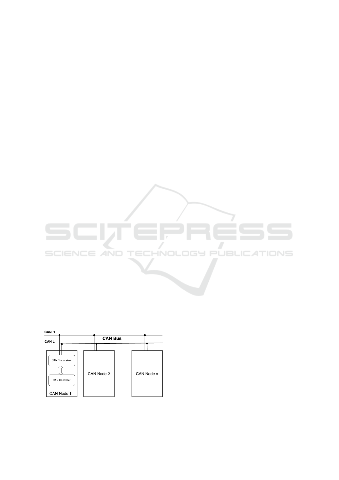
2.1 Multipexing in CAN Bus
The CAN bus is a widely used communication net-
work in modern vehicles (Prerana et al., 2024). It en-
ables data exchange between various electronic com-
ponents of the vehicle. The multiplexing reduces
wiring complexity while optimizing the efficiency of
information exchange, and enables multiple distinct
frames to be transmitted over a single network. Op-
erating on a shared bandwidth principle, each frame
is assigned a unique identifier and prioritized ac-
cordingly. This mechanism ensures efficient network
management and minimizes latency by prioritizing
critical frames, even in high-traffic conditions. For in-
stance, real-time data from the ABS (Anti-lock Brak-
ing System) or engine sensors is given precedence
over less critical signals, such as air conditioning set-
tings. Figure 1 shows the topology of a CAN network.
Figure 1: CAN Topology.
2.2 Data Format
The CAN bus data format is organized into frames
(Hossain et al., 2020), with each frame representing a
message exchanged between various vehicle compo-
nents. Each frame is assigned a unique identifier, and
its structure is defined by specific fields, as detailed in
Table 1. The composition of fields varies depending
on whether the frame is a standard or extended type.
2.3 MT-CAN-LIN-BSI Model
The model is developed and marketed under the
EXXOTEST brand (Exxotest, 2024). It represents a
cutting-edge generation of vehicle technology, incor-
porating full CAN components from the car model of
Citro
¨
en C4 (C5 Restyled) and Peugeot 307. It features
manufacturer-specified communication buses, includ-
ing high-speed CAN, low-speed CAN, and LIN (Lo-
cal Interconnect Network). Furthermore, the model is
paired with MUXTRACE software and a USB-MUX-
4C2L unit, enabling seamless viewing, analysis, and
transmission of data frames across the system’s buses.
The hardware provided for the vehicle prototype
includes a range of components designed to simu-
late real vehicle systems and ensure accurate data col-
lection. Additionally, the prototype features essen-
tial subsystems, such as the air conditioning control
screen, the multifunction display, and various control
panels for electric windows and rear-view mirrors.
These elements contribute to simulating the vehicle’s
user interface and control functions, while ensuring a
realistic and comprehensive driving experience.
Figure 2 illustrates the general block diagram of
the vehicle’s networks, highlighting the physical con-
nections and data flows involved in acquiring infor-
mation from the prototype’s sensors. This diagram
outlines the system’s overall architecture, including
the sensors, ECUs, CAN and LIN buses. To power
the entire setup, the system includes an energy supply
composed of a power source and a battery simulat-
ing real-world vehicle conditions. These structured
connections enable reliable data collection and facil-
itate its analysis for modeling and anomaly detection
purposes. For a comprehensive understanding of the
component codification and detailed wiring informa-
tion, readers are encouraged to refer to the official
manual provided in (Exxotest, 2024).
In the vehicle prototype, each component is as-
signed a unique code by the manufacturer. These
codes serve to distinguish electronic modules, stream-
line their communication via the CAN and LIN buses,
and facilitate their referencing in analysis software.
This coding system not only simplifies the diagnosis
Toward Optimized Predictive Maintenance for Vehicle Systems: Deep Learning-Based Anomaly Detection Using CAN Traffic
419

Table 1: Detailed Overview of CAN Frame Fields.
Field Length Description
Start-of-frame 1 bit Indicates the beginning of the CAN frame.
Identifier 11/29 bits Specifies the frame’s priority on the CAN bus (standard
or extended).
RTR (Remote Transmission Request) 1 bit Distinguishes between a data frame (0) and a remote
request (1).
IDE (Identifier Extension Bit) 1 bit Indicates whether the identifier is standard or extended.
DLC (Data Length Code) 4 bits Represents the length of the data in the message (0–8
bytes).
Data 0-64 bits Contains the actual message data.
CRC (Cyclic Redundancy Check) 15 bits Ensures data integrity by detecting transmission errors.
ACK (Acknowledge) 2 bits Confirms that the frame has been successfully received.
End-of-frame 7 bits Marks the end of the CAN frame.
and management of the simulated electronic compo-
nents but also aligns with the industrial standards used
in real-world vehicles. Table 2 provides an example
of coding system, offering an overview of the proto-
type’s key components and their roles.
Table 2: Example of manufacturer codes.
Manf. code Component name
0004 Instrument panel
BSI1 Built-in Systems Interface (BSI)
PSF1 Fuse box in engine compartment
1282 Additive control unit
1630 Automatic transmission control unit
7500 Parking aid control unit
8080 Air conditioning control unit
The Built-in Systems Interface (BSI) is an inte-
grated system that centralizes and manages data from
vehicle sensors. Serving as a CAN coordinator and
gateway, it also functions as a security system, diag-
nostic tool, and driver assistance system. BSI reduces
wiring complexity, offering both economic and tech-
nical advantages.
The Power Supply Fuseboard (PSF), located in the
engine compartment, is critical for the safe and effi-
cient operation of the vehicle’s electrical system. It
houses a series of fuses and relays designed to protect
the vehicle’s electrical circuits by interrupting the cur-
rent in the event of an overload or short circuit. Each
fuse within the PSF acts as a safety device, ensuring
the integrity of critical components. This protection
mechanism prevents damage to sensitive electronics
and ensures stable power distribution.
Retrieving data from each module in the prototype
requires establishing connections to the designated
outputs on the breakout box, which are clearly labeled
with specific numbers corresponding to the compo-
nent codes within the system. The outputs grant ac-
cess to the data transmitted by various modules, in-
cluding sensors, control units, and other electronic
components. This setup ensures precise traceability
and accuracy in the data collection process, thereby
facilitating a foundation for experimental analysis.
3 OUR EXPERIMENTAL SETUP
In this section, we describe our experimental setup
on the vehicle prototype. We delve into the details
of the data collection process, covering the technical
intricacies of the wiring, as well as the configuration
settings employed for data extraction.
3.1 Study Context and Objectives
The primary aim of this experiment is to capture and
analyze data from a vehicle operating under normal
driving conditions. This study focuses on acquiring
critical parameters that provide insights into both the
vehicle’s dynamics and its control systems. The tar-
geted parameters include speed, vehicle suspension
height, headlight position, steering wheel angle, and
engine revolutions per minute (RPM). These parame-
ters are broadly categorized into two key groups:
• Vehicle Dynamics Parameters: This category
encompasses speed and engine RPM, both of
which are fundamental for assessing the vehi-
cle’s performance and operational state. Speed
data offers real-time insights into the vehicle’s
movement, enabling evaluations of overall mo-
tion, such as braking distance, acceleration pat-
terns, and fuel efficiency. Meanwhile, engine
RPM serves as a vital indicator of the engine’s
workload and performance, providing a detailed
understanding of engine efficiency and opera-
tional stability under varying driving conditions.
ICPRAM 2025 - 14th International Conference on Pattern Recognition Applications and Methods
420
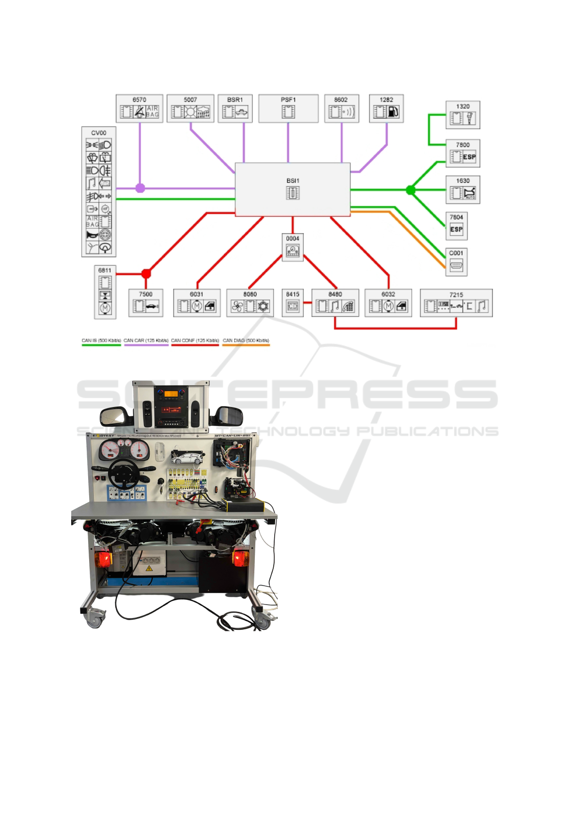
Figure 2: CAN-LIN-BSI’s wiring diagram (Exxotest, 2024).
Figure 3: Vehicle prototype.
• Direction Control Parameters: This category
includes the steering wheel angle, headlight di-
rection, and vehicle suspension height, which are
intricately linked to the vehicle’s directional and
safety systems. The steering wheel angle directly
reflects the vehicle’s directional intent, while the
headlight direction dynamically adjusts based on
the steering angle to ensure optimal illumination
during turns. Additionally, the vehicle suspension
height facilitates the adjustment of headlight ele-
vation, enhancing visibility and safety across di-
verse driving environments.
The overarching objective of this study is to ex-
tract these parameters through the CAN bus, enabling
an in-depth analysis of the vehicle’s dynamic behav-
ior. This approach allows for the identification of
potential anomalies, providing valuable insights into
system reliability and supporting the advancement of
predictive maintenance techniques.
3.2 Physical Settings
Figure 3 provides an overview of the complete proto-
type, while Figure 4 offers a detailed, zoomed-in view
of our configuration and wiring setup. These figures
highlight the physical layout and the implementation
of the wiring diagrams, offering a comprehensive un-
derstanding of the system’s architecture and support-
ing the experimental methodology.
We employed the USB-MUX-4C4L and USB-
MUX-6C6L units as integral components of our data
acquisition system. The USB-MUX-6C6L served as
the primary interface, connecting the CAN bus to the
Toward Optimized Predictive Maintenance for Vehicle Systems: Deep Learning-Based Anomaly Detection Using CAN Traffic
421
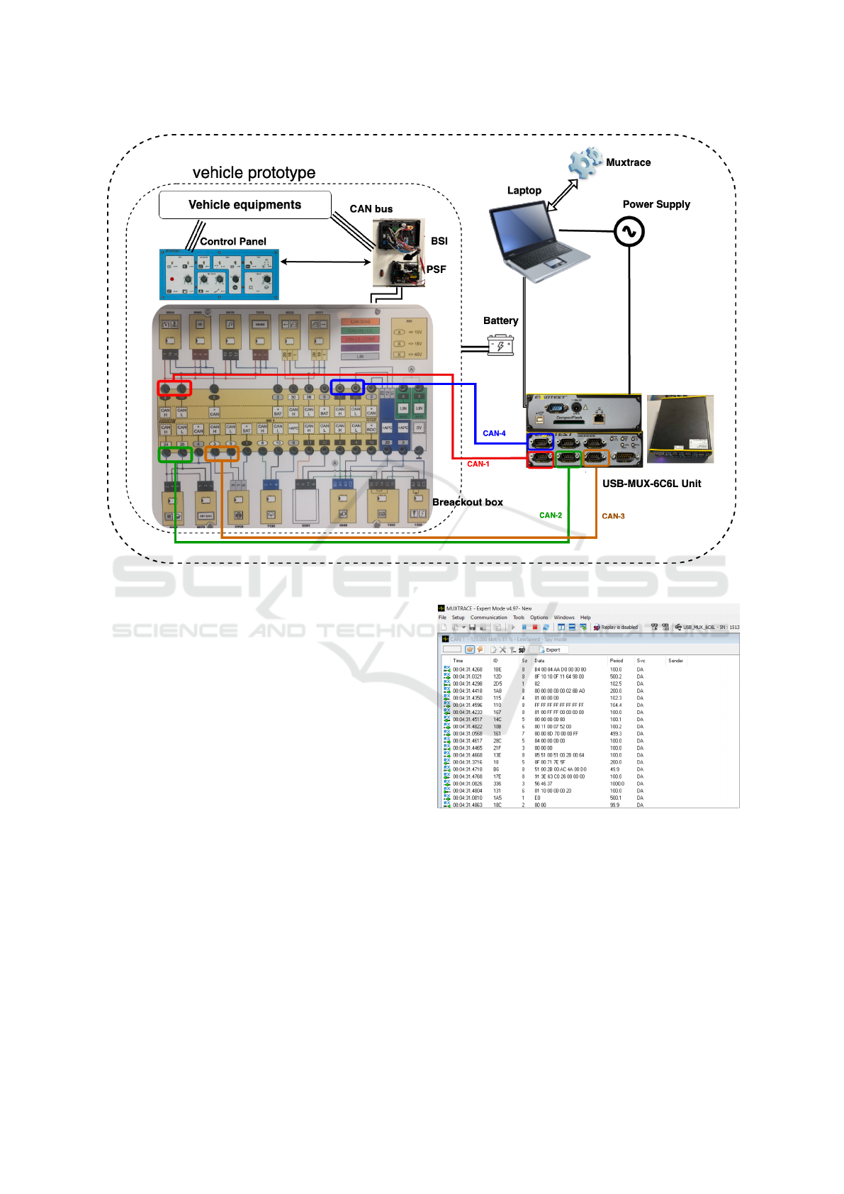
Figure 4: Prototype description diagram.
laptop and enabling seamless integration of multiple
CAN channels. This unit ensured reliable and accu-
rate recording of CAN traffic, facilitating robust com-
munication between the system’s components. Com-
plementing this hardware, the Muxtrace software, in-
stalled on the laptop, enabled real-time capture, mon-
itoring, and analysis of all CAN messages exchanged
during the experiment. To capture critical vehi-
cle metrics, we activated four distinct data sources:
CAN-1, CAN-2, CAN-3, and CAN-4—which al-
lowed for the acquisition of key parameters, includ-
ing speed, vehicle suspension height, headlight po-
sition, steering wheel angle, and engine RPM. The
use of multiple CAN channels ensured comprehen-
sive and precise data collection, providing a detailed
understanding of the vehicle’s dynamic behavior. Ad-
ditionally, the control panel played a crucial role in
the experimental setup by enabling the generation of
inputs and adjustment of variables such as parking,
fuel level, airbag status, and stop lamp switch. This
capability allowed us to simulate and test the vehi-
cle’s behavior under diverse configurations, ensuring
a thorough evaluation of the system’s performance.
Figure 5: Data extraction.
3.3 Software Settings
A key software tool utilized in this configuration is
Muxtrace, a specialized application designed for the
advanced analysis and emulation of communication
protocols, including CAN and LIN networks. Mux-
trace enables real-time monitoring, diagnostics, and
detailed analysis of communication traffic, signifi-
cantly enhancing the accuracy, granularity, and depth
of the experimental data collected from the vehicle’s
communication networks. This capability is partic-
ICPRAM 2025 - 14th International Conference on Pattern Recognition Applications and Methods
422
ularly valuable for isolating irregularities and under-
standing temporal relationships within the data. Fig-
ure 5 provides a visual representation of real-time data
acquisition we had using Muxtrace software.
Each data source (CAN bus i) that we managed
through the USB-MUX-4C4L unit corresponds to the
signals received from various components of the ve-
hicle system, such as sensors, actuators, and con-
trol units. The physical connections between these
components are implemented according to the design
specifications defined by the EXXOTEST model. The
acquired data is systematically stored in .asc files,
where each file represents a dataset corresponding to
a specific CAN bus. Within these files, each line
signifies a frame transmitted in accordance with a
predefined cycle. The structure of these frames in-
cludes several key fields: Transmission Type (Rx/Tx),
Timestamp, Identifier, Data Size, Transmission Pe-
riod, and Service Code.
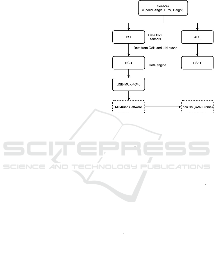
The flow of data collection is illustrated in Figure
6, providing a comprehensive depiction of the infor-
mation pipeline from the vehicle’s sensors to the final
output. The process begins with sensors transmitting
raw data to the BSI, which centralizes, processes, and
disseminates the data via the CAN and LIN buses.
The PSF and ECU further process key parameters
such as speed and RPM, while simultaneously adjust-
ing critical systems, including headlight direction, to
ensure vehicle performance. The USB-MUX-4C4L
unit serves as the intermediary interface, capturing
and streaming these data signals to the Muxtrace soft-
ware, which logs and visualizes the communication
in real time. Finally, the data is archived in .asc files,
enabling structured storage for our post-experiment
analysis.
1
4 OBTAINED RESULTS
4.1 Preprocessing and Model Training
To train our anomaly detection model, we used the
CAN traffic data from the vehicle platform, extract-
ing frames from four distinct sources: CAN-1, CAN-
2, CAN-3, and CAN-4. Each source’s raw ASC
log file was converted into a structured CSV dataset.
During this preprocessing step, key fields such as
1
To advance the broader research community, we have
made the dataset generated from our experiments publicly
accessible on Kaggle (VehicleCANData, 2024). This re-
source is intended to facilitate further research in vehicle
diagnostics, anomaly detection, and predictive maintenance
systems, fostering innovation in intelligent automotive sys-
tems.
Figure 6: Data flow.
timestamp, port number, id, direction, type, length,
and payload were extracted. Due to the length of the
latter parameter, we split it in 8 fragments: payload 1
to payload 8. Missing values were replaced with
0 to maintain a consistent format, and all hexadeci-
mal fields, including id and payload 1 to payload 8,
were converted to their integer equivalents. Addi-
tionally, the direction field was encoded into a binary
format, where Rx was replaced with 1 and T x with
0. After cleaning and formatting, only the relevant
columns (timestamp, id, direction, and payload 1 to
payload 8) were retained.
The anomaly detection model was built using a
Long Short-Term Memory (LSTM) neural network.
First, each dataset was loaded and prepared by gen-
erating sequences of data with a sequence length of
10. For each sequence, features such as id, delta time
(the time difference between consecutive messages),
and payload 1 to payload 8 were included. The
delta time was calculated directly from the times-
tamp column. A sliding window approach was em-
ployed to create sequences, ensuring that data was
correctly shaped for input into the model.
The LSTM model architecture consisted of an ini-
tial LSTM layer with 64 neurons and a dropout rate of
20%, followed by a second LSTM layer with 32 neu-
rons and another dropout layer. The output layer was
a fully connected dense layer with a sigmoid activa-
tion function, designed for binary classification (nor-
mal or abnormal CAN traffic). The CAN traffic is
considered normal, if the output is greater than 0.5.
Toward Optimized Predictive Maintenance for Vehicle Systems: Deep Learning-Based Anomaly Detection Using CAN Traffic
423
The model was compiled using the Adam optimizer
with Mean Squared Error (MSE) loss. MSE quan-
tifies the average squared difference between pre-
dicted and actual values, making it a suitable metric
for this application. Training was conducted on an
80% − 20% split of the data into training and valida-
tion sets, with stratified sampling ensuring balanced
representation.
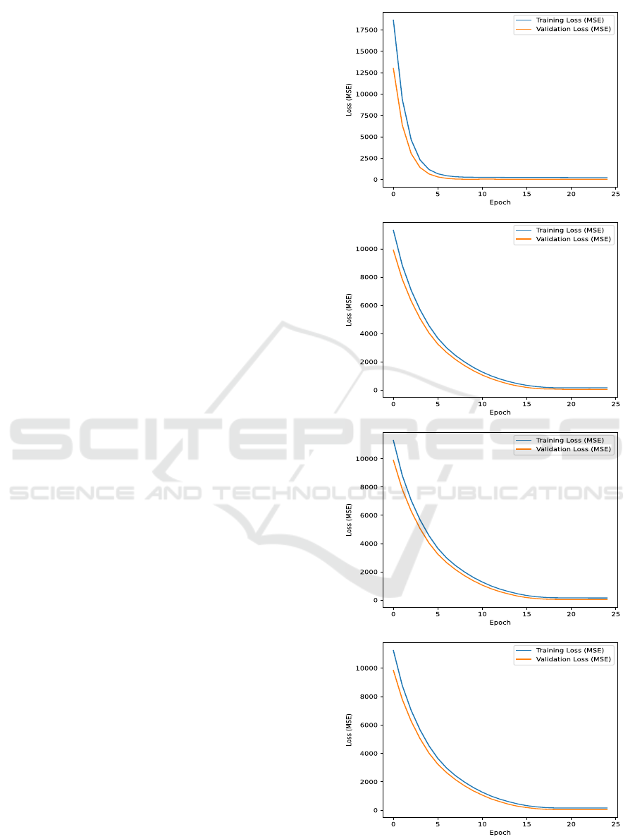
Figure 7 illustrates the training and validation
MSE loss curves in function of the number of epochs.
The evaluation is focused on assessing the normal-
ity of CAN traffic, using the MSE loss as an indica-
tor for deviations or anomalies. The training phase
spanned 47 minutes, conducted on an Apple M1 ma-
chine equipped with 32GB of memory. The results
demonstrate a steady decrease in both training and
validation loss, converging to minimal values by the
end of training. This indicates that the model effec-
tively learned the underlying patterns in the data while
avoiding overfitting. The loss curves also highlight
the stability of the training process, as no significant
fluctuations are observed. The convergence of train-
ing and validation loss suggests that the model gen-
eralizes well to unseen data. Overall, the use of the
LSTM model successfully captures temporal depen-
dencies in CAN bus data, enabling robust anomaly
detection for predictive maintenance.
4.2 Recommendations for Deployment
The deployment of the trained anomaly detection
model in real-world vehicle systems requires its in-
tegration into the vehicle’s electronic architecture to
enable predictive maintenance. This integration in-
volves embedding the model into an automotive-
grade microcontroller or an edge computing device
capable of real-time inference. These processing units
interface with the CAN bus to ingest and process data
streams from the vehicle parameters (for instance, re-
garding our use case: speed, engine RPM, steering
wheel angle, vehicle suspension height, and headlight
direction).
To replicate the training pipeline during deploy-
ment, the embedded system must include preprocess-
ing functionalities such as decoding the data into in-
tegers, calculating the delta time between consecu-
tive frames, and fragmenting payloads into structured
inputs compatible with the model. The real-time
data captured from the CAN bus is then processed
and passed to the model for inference, which outputs
anomaly predictions with minimal latency. The de-
tected anomalies are communicated to the vehicle’s
diagnostic system via CAN frames or other communi-
cation protocols. These diagnostics can be logged and
CAN-1
CAN-2
CAN-3
CAN-4
Figure 7: Model Training Results.
ICPRAM 2025 - 14th International Conference on Pattern Recognition Applications and Methods
424

visualized for actionable insights, enabling drivers
and maintenance systems to respond proactively. For
instance, abnormal spikes in engine RPM or sudden
fluctuations in vehicle suspension height could indi-
cate drivetrain or suspension issues, prompting tar-
geted inspections. This proactive approach reduces
unscheduled downtime and prevents critical failures.
Beyond standalone deployment, a fusion predic-
tion framework can be implemented to enhance the
robustness of anomaly detection. The submodels
trained on specific parameter groups can be aggre-
gated into a unified fusion model. Ensemble tech-
niques, such as weighted averaging or majority vot-
ing, can be used to combine predictions from indi-
vidual submodels. This framework leverages correla-
tions between interdependent metrics, such as steer-
ing angle and headlight alignment, to detect complex
fault patterns that may be missed by standalone mod-
els. Furthermore, the fusion approach reduces false
positives by validating anomalies across multiple pa-
rameter sets, improving system reliability.
Finally, integrating the model with a driver feed-
back system enhances usability. Detected anomalies
can trigger dashboard alerts with actionable recom-
mendations, such as Inspect Engine or Check Suspen-
sion, providing real-time insights for drivers. This
feedback loop improves safety and allows for timely
maintenance interventions, minimizing potential risks
and ensuring vehicle reliability.
5 CONCLUSION
In this paper, we developed a deep learning-based
framework for predictive maintenance in vehicle sys-
tems, leveraging anomaly detection on CAN bus data.
The experimental results revealed the model’s capa-
bility to capture temporal dependencies and identify
anomalies with high precision, ensuring enhanced re-
liability and safety in vehicle operations. Our contri-
butions include the development of a robust prepro-
cessing pipeline tailored to CAN bus data, the de-
sign of an LSTM-based anomaly detection model,
and practical recommendations for its real-world de-
ployment. The proposed system offers a proactive ap-
proach to maintenance, enabling timely fault detec-
tion and reducing vehicle downtime. By correlating
critical parameters such as speed, engine RPM, steer-
ing wheel angle, and headlight direction, the frame-
work supports a holistic view of vehicle health and
operational performance.
Looking ahead, our future work focuses on ex-
tending the experimental setup to test the real-time
capabilities of the trained model under more dynamic
conditions. Specifically, we are conducting experi-
ments to inject faulty CAN frames into the bus traf-
fic to evaluate the model’s ability to detect anomalies
in real-time. The breakout box, an essential compo-
nent, is used to access specific communication lines
and electrical signals within the vehicle prototype, al-
lowing the orchestration of faults within the system.
This study will provide deeper insights into the ro-
bustness and responsiveness of the model in identify-
ing security vulnerabilities and operational faults in
live vehicle environments. Moreover, future efforts
will explore the integration of federated learning, to
ensure the system’s adaptability across different vehi-
cle types and operational conditions.
REFERENCES
Aeddula, O., Frank, M., Ruvald, R., Askling, C. J., Wall,
J., and Larsson, T. (2024). Ai-driven predictive main-
tenance for autonomous vehicles for product-service
system development. Procedia CIRP, 128:84–89.
34th CIRP Design Conference.
Arena, F., Collotta, M., Luca, L., Ruggieri, M., and Ter-
mine, F. (2021). Predictive maintenance in the auto-
motive sector: A literature review. Mathematical and
Computational Applications.
Exxotest (2024). https://www.exxotest.com/.
Hossain, M. D., Inoue, H., Ochiai, H., Fall, D., and
Kadobayashi, Y. (2020). An effective in-vehicle can
bus intrusion detection system using cnn deep learning
approach. In GLOBECOM 2020-2020 IEEE global
communications conference, pages 1–6. IEEE.
Johnson, N., Ewards, S. V., Silas, S., and Kathrine, G. J. W.
(2024). Predictive vehicle maintenance using deep
neural networks. In 2024 International Conference
on Cognitive Robotics and Intelligent Systems (ICC -
ROBINS), pages 322–326.
Lindemann, B., Maschler, B., Sahlab, N., and Weyrich, M.
(2021). A survey on anomaly detection for technical
systems using lstm networks. Computers in Industry,
131:103498.
Prerana, S., Reddy, N. N., Varghese, S. G., and Sabhahit,
J. N. (2024). Review on communication technologies
used in electric vehicles. In 2024 IEEE International
Conference on Distributed Computing, VLSI, Electri-
cal Circuits and Robotics (DISCOVER), pages 445–
451. IEEE.
Rokicki, K., Brukalski, M., and Sar, H. (2020). Applica-
tion of can bus data in road tests of automobiles. In
2020 XII International Science-Technical Conference
AUTOMOTIVE SAFETY, pages 1–4.
Sokolovskij, E. and
ˇ
Zuraulis, V. (2024). Advances in vehi-
cle dynamics and road safety: Technologies, simula-
tions, and applications.
VehicleCANData (2024). Vehicle can data. https://www.
kaggle.com/datasets/vehiclecandata/dataset.
Toward Optimized Predictive Maintenance for Vehicle Systems: Deep Learning-Based Anomaly Detection Using CAN Traffic
425
