
Low Power Logarithmic Current-to-Digital Converter (CDC) Inspired
by Molecular Genetic Processes for Biomedical Applications
Oren Ilan, Gupta Vishesh and Daniel Ramez
Faculty of Bio-Medical Engineering, Technion, Israel Institute of Technology, Haifa 3200003, Israel
Keywords:
Current to Digital Converter (CDC), Logarithmic ADC, Low Power, Subthreshold Analog Circuits, Neural
Network, Bio-Inspired, Biomedical Applications, Adaptive Systems.
Abstract:
A Bio-inspired low-power logarithmic Current-to-Digital Converter is presented. The main building block of
the CDC is a computing unit named Perceptgene (PG) that was inspired by molecular biology and has training
and computing capabilities in the log domain (Rizik et al., 2022). The Perceptgene which models a nonlinear
molecular behavior was implemented using a translinear subthreshold electronic circuit (Oren et al., 2023).
Thus the CDC design which uses the Perceptgene building block operates more naturally in the Log domain
and is expected to consume low power which can make it usable for biomedical applications.
1 INTRODUCTION
The need to process biomedical signals using
portable, wearable or implantable electronic devices
has increased significantly in recent years. These de-
vices are operated by minor batteries thus an energy-
efficient ADC became a fundamental component.
Biosensors are widely used in applications such as
Glucose monitoring, DNA sequencing, food analysis,
and microorganism analysis. Some of these biosen-
sors, translate a biological marker that changes in the
logarithmic scale (Thanachayanont, 2015) to a cur-
rent output signal, thus a logarithmic CDC is a more
natural readout device for them. In addition, a log-
arithmic ADC (Sit and Sarpeshkar, 2004) (Mahat-
tanakul, 2005) (Rhew et al., 2014) (Sundarasaradula
et al., 2016) (Danial et al., 2019) can perform analog-
to-digital conversions with non-uniform quantization
thus it can convert small signals with high resolu-
tion and large signals with coarse resolution, which
enables handling large input dynamic range signals
with a lower number of bits compared to a linear
ADC. The lower number of bit results a lower power
and smaller area. In this study, we propose ultra-
low power electronic circuits inspired by gene net-
works to demonstrate the computational abilities of
neuronal networks. This approach relies on insights
we have gained that map neuronal networks to molec-
ular biological systems (biomorphic (Rizik et al.,
2022) (Daniel et al., 2013)) and then to electronic cir-
cuits (cytomorphic (Sarpeshkar, 2011) (Hanna et al.,
2020)), as shown in (Fig. 1). Previously (Rizik
et al., 2022) we proposed the perceptgene neural
model that was inspired by molecular biology and
implemented it (Oren et al., 2023) using a translin-
ear (Gilbert, 1975) subthreshold electronic circuit that
enables low-power computation at the log domain.
Implementing CDC using the perceptgene build-
ing block will enable more natural operation in
the Log domain and ultra-low power consumption,
thus will better suit biomedical systems.
Figure 1: Neural model inspired by molecular biology and
implemented by analog circuit for bio-medical applications.
This paper describes a new concept for imple-
menting a logarithmic current to digital converter us-
ing PG building blocks.
210
Ilan, O., Vishesh, G. and Ramez, D.
Low Power Logarithmic Current-to-Digital Converter (CDC) Inspired by Molecular Genetic Processes for Biomedical Applications.
DOI: 10.5220/0013376900003911
Paper published under CC license (CC BY-NC-ND 4.0)
In Proceedings of the 18th International Joint Conference on Biomedical Engineering Systems and Technologies (BIOSTEC 2025) - Volume 1, pages 210-215
ISBN: 978-989-758-731-3; ISSN: 2184-4305
Proceedings Copyright © 2025 by SCITEPRESS – Science and Technology Publications, Lda.
2 PERCEPTGENE BUILDING
BLOCK
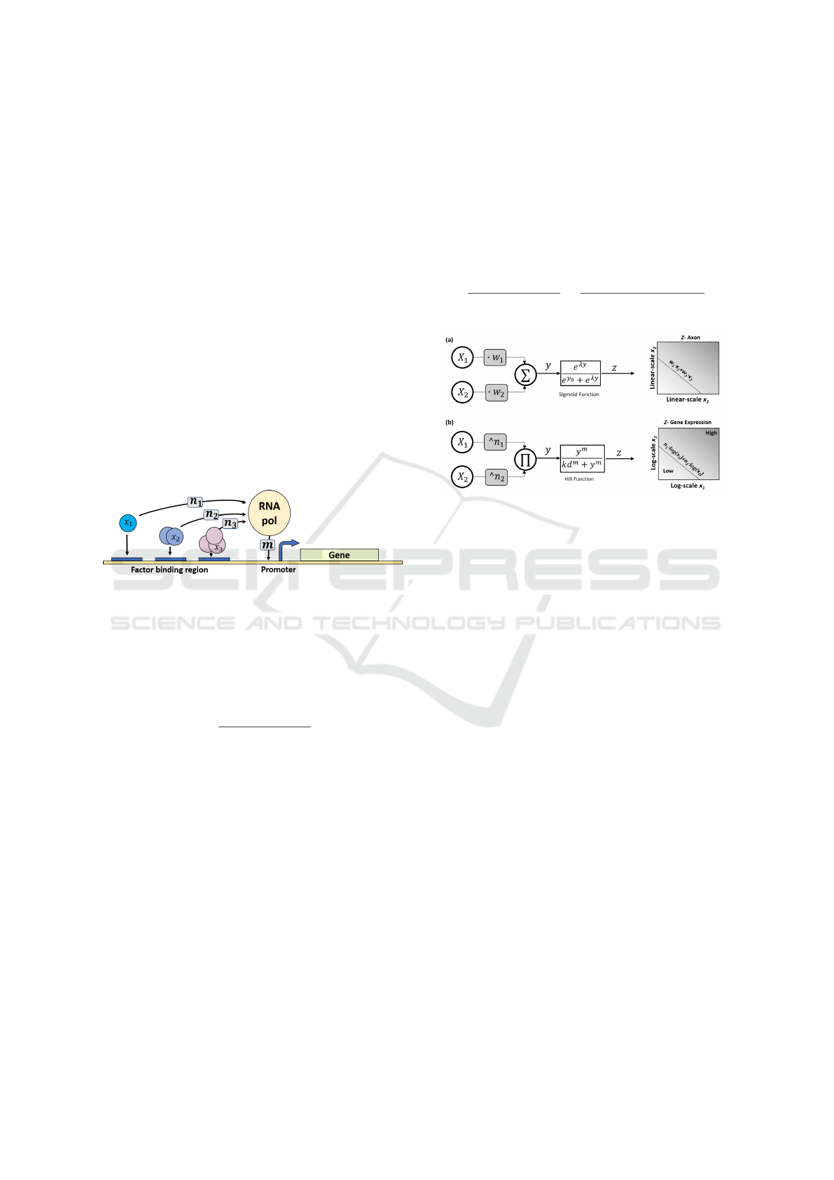
2.1 Bio-Molecular ”Neuron”
Our neural model was inspired by combinatorial gene
regulation kinetics of promoter activation (Fig. 2) . A
combinatorial promoter is regulated by multiple tran-
scription factors x
i
, each transcription factor binds to
its designated region and afterward participates in re-
cruiting the RNA polymerase to form the activation
complex. In our model, several biological parame-
ters are involved, such as the biological cooperativ-
ity of proteins, the number of binding sites in the
promoter, the protein quaternary structure, and the
binding affinities of protein-protein/protein-DNA re-
actions. In this process, multiple transcription factors
participate and bind upstream to a gene sequence. To-
gether they facilitate the binding of RNA polymerase
to the promoter region forming the activation complex
that initiates gene transcription.
Figure 2: Anatomy structure of operating principles of gene
regulatory network.
For a combinatorial activation, the relation be-
tween the transcription factors concentration and the
promoter transcription rate, under certain conditions
(Bintu, 2005), can be simplified and modeled as fol-
lows:
P =
(
∏
N
i
x
n
i
i
)
m
(
∏
N
i
x
n
i
i
)
m
+ kd
m
(1)
Where P is the activation rate, x
i
is the transcrip-
tion factor concentration, n
i
is the Hill coefficient of
transcription factor i associated with the activation
complex formation, m is the Hill coefficient for the
binding of the activation complex with the promoter
and k d is the dissociation constant for the complex
binding with the promoter.
By applying a logarithmic transform to Eq. 1, we
obtain a new abstract model (Fig. 3b) analogous to
the perceptron model (Fig. 3a) that is used in artificial
neural networks (Haykin, 2004) . Similar to other arti-
ficial neuron models that operate as binary classifiers,
this model achieves classification via a weighted in-
put integration followed by a threshold activation for
the output. However, three notable differences exist.
First, the weighing of the inputs is done here accord-
ing to a power law and not multiplication. Second, the
inputs are integrated via a product rather than a sum-
mation. And third, the activation function used for
this model is the Hill equation instead of the standard
logistic function. Interestingly the perceptgene model
can be viewed as a perceptron with a log transform
over its input dynamic range, the proof is straightfor-
ward from the following equality:
P =
(
∏
N
i
x
n
i
i
)
m
(
∏
N
i
x
n
i
i
)
m
+ kd
m
=
e
m
∑
N
i
n
i
Ln(x
i
)
e
m
∑
N
i
n
i
Ln(x
i
)
+ e
mLn(kd)
(2)
Figure 3: Abstract artificial intelligence models for (a) per-
ceptron inspired by neural networks: x
i
are the inputs, w
i
are
multiplicative weights, input integration is done via sum-
mation, and the activation function is the sigmoid function.
Depicted on the right is the resulting linear separable clas-
sification of the analog inputs x1 and x2 (b) perceptgene
inspired by genetic networks: x
i
are the inputs, n
i
are power
weights, input integration is done via a product, and the acti-
vation function is the Hill equation. Depicted on the right is
the resulting logarithmically separable classification of the
analog inputs x1 and x2.
2.2 Perceptgene Circuit Design
After the perceptgene circuit was implemented as de-
scribed in detail at (Oren et al., 2023), the main
goal was moving from ideal structures to real devices
which can be implemented in silicon. The voltage di-
vider of the power circuit which requires huge Giga
ohms resistors was a significant challenge and it was
decided to implement it using two capacitors that are
connected in series as can be viewed at the exponen-
tial function circuit in Fig. 4. The disadvantage of this
implementation compared to regular resistors is the
need to deal with the dynamic behavior of the divider.
A slight change in the values of these capacitors will
enable tuning the binary weights as required.
In order to implement the CDC’s voltage digital
output, we had to convert the output current signals of
the original perceptgene to a voltage signal. This was
achieved by the digital buffer added at the output of
the activation function as can be viewed in Fig. 4. The
activation function with the output buffer operates as
Low Power Logarithmic Current-to-Digital Converter (CDC) Inspired by Molecular Genetic Processes for Biomedical Applications
211

a current comparator with a threshold that can be set
by Ikd current.
Figure 4: Perceptgene circuit building block.
3 LOGARITHMIC CDC:
CONCEPT AND
ARCHITECTURE
3.1 CDC Basic Concept
A 3-bit logarithmic CDC was designed using three
perceptgenes cells. The architecture of the CDC can
be viewed in Fig. 5 below. The input current is fed
to the three PG units and an output digital code rep-
resenting the value of the input current in the log do-
main is generated at the voltage outputs D0, D1, D2.
The output code is calculated based on the reference
current of each unit (Irefi) while taking into account a
feedback value from higher bits. The weight for each
input is marked as nij.
Figure 5: Perceptgene-based Log CDC architecture.
The perceptgene modeled in Fig. 3b can be written
as a sigmoid (Eq. 2) that operates on the Log of the
input Ii as follows:
PGi =
e
m
∑
N
i
n
i
Ln(I
i
)
e
m
∑
N
i
n
i
Ln(I
i
)
+ e
mLn(Ikd)
(3)
For N=3, Kd=1, m=1, the sigmoid (Eq. 3) transi-
tion points for the PGi units in Fig. 5 are given by
ln(I
in
) · n21 + ln(I
2
) · n22 − ln(I
re f 2
) = 0 (4)
ln(I
in
) · n11 + ln(I
2
) · n12 − ln(I
re f 1
) = 0 (5)
ln(I
in
) · n01 + ln(I
2
) · n02 + ln(I
3
) · n03
− ln(I
re f 0
) = 0 (6)
The required weights nij should be as in Fig. 6 and
will be explained for each of the CDC bits.
For bit D2 (MSB), the transition at the CDC output is
defined by Eq.4. Since no feedback from the previous
stage and since the detected input should be 0.5 of the
Max input logarithmic value:
ln(I
2
) = 0, ln(I
in
) = 0.5 · ln(I
max
)
Therefore the reference value should be :
=⇒ ln(I
re f 2
) = 0.5 · ln(I
max
) (for n21, n22 = 1)
For bit D1, the transition at the CDC output is de-
fined by Eq.5. In case no feedback from a higher bit
(D2), the detected input should be 0.25 of the Max
input logarithmic value and therefore the reference
value should be:
=⇒ ln(I
re f 1
) = 0.25 · ln(I
max
) (for D1 = 0)
If the higher bit (D2) is high, the detected input
should be 0.75 of the Max input logarithmic value.
Therefore, the current on the second input should be:
=⇒ n11 · ln(I
2
) = −0.5 · ln(I
max
)
For bit D0 (LSB), the transition at the CDC output
is defined by Eq.6. In case no feedback from higher
bits (D1, D2), the detected input should be 0.125 of
the Max input logarithmic value and therefore the ref-
erence value should be:
=⇒ ln(I
re f 0
) = 0.125 · ln(I
max
) (for D1, D2 = 0)
If the higher bits (D1, D2) are 1, the detected input
should be 0.875 of the Max input logarithmic value
and therefore the current on the second and third in-
puts should be :
=⇒ n02 · ln(I
2
) = −0.25 · ln(I
max
)
=⇒ n03 · ln(I
3
) = −0.5 · ln(I
max
)
3.2 CDC Practical Topology
Implementing the above equations required using an
architecture with negative weights and a perceptgene
with 3 inputs which complicates the design signifi-
cantly. Yet, an input with a negative weight can be re-
placed by an input with a positive weight which multi-
plies Iref as can be viewed in the following equations:
y =
Iin
1
∗ x
−0.5
2
∗ I
−0.25
3
I
0.125
re f
(7)
BIODEVICES 2025 - 18th International Conference on Biomedical Electronics and Devices
212
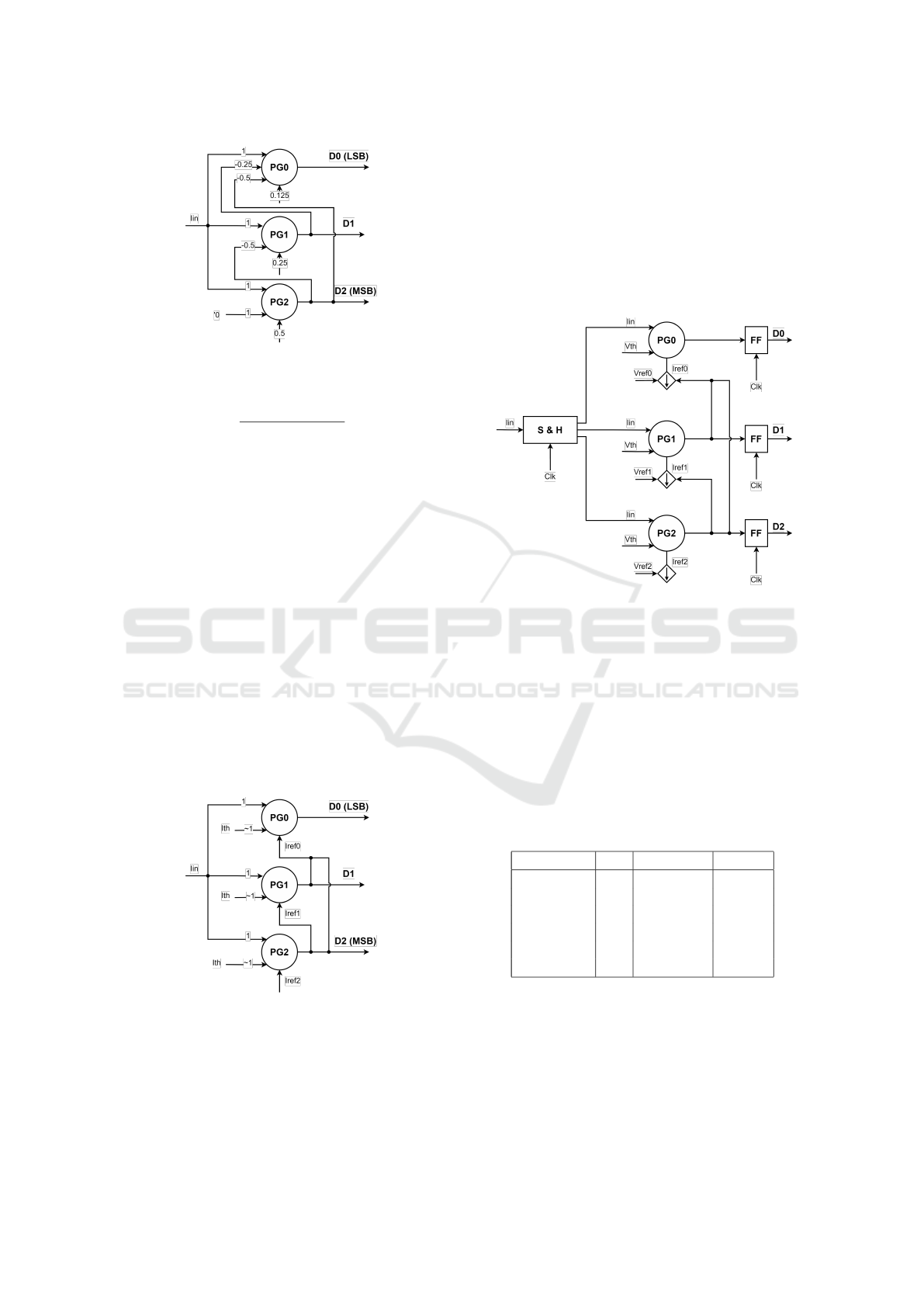
Figure 6: Basic topology of 3 bits CDC.
y =
I
1
in
I
0.125
re f
∗ I
0.5
2
∗ I
0.25
3
Following the above changes, the updated archi-
tecture of the CDC can be viewed in Fig. 7. In this
architecture, the feedback from higher bits was inte-
grated into the Iref input, thus enabling the use of the
original perceptgene building block which includes
only 2 inputs with positive weights. The second input
of the PG is the Ith, which has the value of the activa-
tion function’s threshold; thus, when Iin equals Irefi,
the multiplication output value is Ith which causes a
transition in the activation function.
In addition to the above changes, the weights were
normalized, and binary weight values were used since
the implementation of binary weights is more simple
than fraction weight implementation. The updated ar-
chitecture of the CDC is close to SAR CDC as the
outputs are impacting the reference (and not the in-
puts as in Pipe CDC). In contradiction to the SAR,
the digital outputs are not converted by a full DAC
but bit by bit.
Figure 7: Final CDC topology.
3.3 CDC Circuit Design
The top-level block diagram of the CDC can be
viewed in Fig. 8. The input current signal Iin is
sampled and then mirrored in each of the three per-
ceptgene blocks. The digital voltage is generated by
each perceptgene based on its reference current (Irefi)
and sampled by FlipFlop. The main current sources
include the reference current source Iref2 and the
switched reference current sources Iref1, Iref0. The
currents on these current sources are being set by ex-
ternal bias voltages Vrefi as can be viewed in this Fig-
ure.
Figure 8: CDC Top level block diagram.
The CDC block diagram in Fig. 8 was imple-
mented using 180nm technology. We decided to im-
plement a 10-base logarithmic CDC but the design
can be easily changed to another logarithmic base.
The minimum input current is 100pa and the maxi-
mum is 1uA, thus requiring only 6 out of the 8 codes
as can be viewed in Table. 1 below. We could use a
serial architecture where the CDC bits are generated
serially by one perceptgen block but we preferred for
simplicity the parallel 3 perceptgene architecture.
Table 1: CDC inputs currents and output codes.
D2 (MSB) D1 D0 (LSB) Iin
0 0 0 0pA
0 0 1 100pA
0 1 0 1nA
0 1 1 10nA
1 0 0 100nA
1 0 1 1uA
Spice simulations were run in order to check the
CDC basic functionality. DC simulation results of the
CDC outputs changing due to input current ramp can
be viewed in Fig. 9(a). The code is changing between
000 to 101 as the input current changes in logarithmic
steps from 10pA to 1uA.
Simulation of a sinus signal in the log domain re-
Low Power Logarithmic Current-to-Digital Converter (CDC) Inspired by Molecular Genetic Processes for Biomedical Applications
213
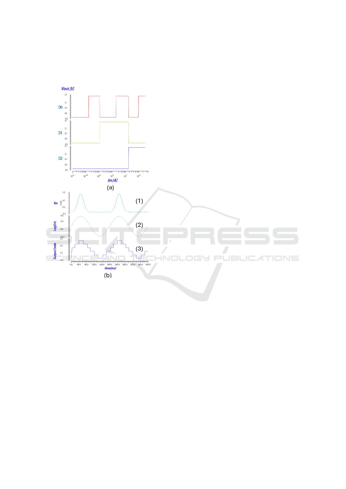
quires inserting a current waveform which is an expo-
nential signal. Such signal can be viewed in Fig. 9b(1)
and the waveform in the log domain which is a pure
sinus in Fig. 9b(2).
Figure 9: Basic functional simulations: (a) DC simulation
of output signals as a function of input ramp current (b)
Transient simulation of output constructed code as a func-
tion of input exponential signal.
Since the CDC converts the logarithmic value
of the input current signal to digital code, the ex-
pected output signal which is constructed by such
code should be a sinus wave. Such sinus signal can
be viewed in Fig. 9b(3)
4 CONCLUSIONS
We propose a novel concept for implementing a log-
arithmic CDC based on a perceptgene building block
inspired by molecular biology. Using perceptgene as
a building block makes the CDC modular and with
the potential for ANN-like training capability. The
modular and flexible architecture enables simple scal-
ing of the design for the required numbers of bits and
different logarithmic bases. The perceptgene was de-
signed using subthreshold translinear analog circuits
that guarantee a low power consumption. Implemen-
tation of the CDC circuits using perceptgene building
block in 180nm technology demonstrates the required
basic functionality and serves as proof of the concept.
The proposed low-power modular logarithmic CDC
might be usable for several biomedical applications.
ACKNOWLEDGEMENTS
We gratefully acknowledge the financial support by
the Israel Ministry of Science (MOS).
REFERENCES
Bintu, L. (2005). Transcriptional regulation by numbers:
models. Curr Opin Genet.
Danial, L., Sharma, K., Dwivedi, S., and Kvatinsky, S.
(2019). Logarithmic neural network data convert-
ers using memristors for biomedical applications. In
2019 IEEE Biomedical Circuits and Systems Confer-
ence (BioCAS), pages 1–4.
Daniel, R., Rubens, J., Sarpeshkar, R., and Lu, T. (2013).
Synthetic analog computation in living cells. Nature.
Gilbert, B. (1975). Translinear circuits: a proposed classifi-
cation. Electron Lett.
Hanna, H., Danial, L., Kvatinsky, S., and Daniel, R. (2020).
Cytomorphic electronics with memristors for model-
ing fundamental genetic circuits. IEEE Transactions
on Biomedical Circuits and Systems.
Haykin, S. (2004). Neural networks: A comprehensive
foundation. Pearson Education.
Mahattanakul, J. (2005). Logarithmic data converter suit-
able for hearing aid applications. Electronics Letters,
41:394 – 396.
Oren, I., Sinni, R. A., and Daniel, R. (2023). Ultra-low
power electronic circuits inspired by biological ge-
netic processes. In BIODEVICES, pages 150–156.
Rhew, H.-G., Jeong, J., Fredenburg, J. A., Dodani, S.,
Patil, P. G., and Flynn, M. P. (2014). A fully self-
contained logarithmic closed-loop deep brain stimu-
lation soc with wireless telemetry and wireless power
management. IEEE Journal of Solid-State Circuits,
49(10):2213–2227.
Rizik, L., Danial, L., Habib, M., Weiss, R., and Daniel, R.
(2022). Synthetic neuromorphic computing in living
cells. Nature communications.
Sarpeshkar, R. (2011). “cytomorphic electronics: cell-
inspired electronics for systems and synthetic biology.
In Ultra Low Power Bioelectronics. Cambridge Uni-
versity Press.
Sit, J.-J. and Sarpeshkar, R. (2004). A micropower loga-
rithmic a/d with offset and temperature compensation.
IEEE Journal of Solid-State Circuits, 39(2):308–319.
BIODEVICES 2025 - 18th International Conference on Biomedical Electronics and Devices
214

Sundarasaradula, Y., Constandinou, T. G., and
Thanachayanont, A. (2016). A 6-bit, two-step,
successive approximation logarithmic adc for
biomedical applications. In 2016 IEEE International
Conference on Electronics, Circuits and Systems
(ICECS), pages 25–28.
Thanachayanont, A. (2015). A 1-v, 330-nw, 6-bit current-
mode logarithmic cyclic adc for isfet-based ph digital
readout system. Circuits, Systems, and Signal Pro-
cessing, 34(5):1405–1429.
Low Power Logarithmic Current-to-Digital Converter (CDC) Inspired by Molecular Genetic Processes for Biomedical Applications
215
