
Manipulating Gloss of Real Objects Under Omnidirectional Lighting
Yuki Miyoshi
1
, Ryo Kawahara
2 a
and Takahiro Okabe
3 b
1
Department of Artificial Intelligence, Kyushu Institute of Technology, Iizuka, Fukuoka 820-8502, Japan
2
Graduate School of Informatics, Kyoto University, Sakyo-ku, Kyoto 606-8501, Japan
3
Information Technology Track, Okayama University, Kita-ku, Okayama 700-8530, Japan
Keywords:
Gloss Manipulation, Omnidirectional Lighting Environment, Specular Reflection, Polarization.
Abstract:
Manipulating the appearances of real-world objects by using active illumination is useful for XR. In this
paper, we propose a method for manipulating the gloss of real objects observed by our naked eyes under
omnidirectional lighting environments. Our proposed method makes use of the fact that specular reflection
components are sensitive to the polarization state of the incident light and the high-frequency components of
the illumination environment, while diffuse reflection components are insensitive to them. Specifically, our
method optimizes the polarization angles and intensities of incident lighting environments for manipulating
the gloss of real objects. We build a lighting system by using a dome screen and two pairs of a projector and a
transmissive LC panel for controlling both the polarization angles and high-frequency components of incident
lighting environments. We conduct a number of experiments, and show that our method achieves the gloss
manipulation without using the geometric and photometric properties of an object of interest.
1 INTRODUCTION
The appearance of an object depends not only on the
geometric and photometric properties of the object
but also on the light sources illuminating it. Manip-
ulating the appearances of real-world objects by us-
ing active illumination such as a projector and a light
stage is useful for XR (extended reality/cross reality).
In this paper, we focus on the gloss manipulation of
real objects under omnidirectional lighting environ-
ments.
A projector (or a projector-camera system) is use-
ful for manipulating the appearance of an object, in
particular for relighting and material editing (Raskar
et al., 2001; Siegl et al., 2015). This is because a
projector can pixel-wisely illuminate the object: it
can illuminate each point on the object surface with
different intensities and colors. Unfortunately, how-
ever, the appearance manipulation using a projector-
camera system requires the geometric and photomet-
ric properties of an object of interest or the light trans-
port of a scene.
On the other hand, a light stage is useful for re-
producing the appearance of an object under omnidi-
a
https://orcid.org/0000-0002-9819-3634
b
https://orcid.org/0000-0002-2183-7112
rectional lighting environments without using the ge-
ometric and photometric properties of the object (De-
bevec et al., 2002; Wenger et al., 2005; Debevec,
2012). Unfortunately, however, it is difficult to ma-
nipulate the reflectance properties of the object, since
each light source illuminates the entire object. Ma et
al. (Ma et al., 2007) capture the specular-free images
under omnidirectional lighting environments by using
a light stage with fixed linear polarizers and a camera
with a linear polarizer. However, the gloss manip-
ulation (emphasis and suppression) observed by our
naked eyes is still an open problem to be addressed.
In this paper, we propose a method for manipulat-
ing the gloss of real objects observed by our naked
eyes under omnidirectional lighting environments.
The key idea of our proposed method is the use of
polarized and high-frequency illumination. Specifi-
cally, we make use of the fact that specular reflectance
is maximal/minimal when the polarization direction
is perpendicular/parallel to the outgoing plane, but
the diffuse reflectance is almost constant according to
the Fresnel equations (Shurcliff, 1962; Wolff, 1990).
In addition, we utilize the fact based on the fre-
quency analysis of reflection that specular/diffuse re-
flection components are sensitive/insensitive to the
high-frequency components of an illumination distri-
bution (Ramamoorthi and Hanrahan, 2001b).
Miyoshi, Y., Kawahara, R. and Okabe, T.
Manipulating Gloss of Real Objects Under Omnidirectional Lighting.
DOI: 10.5220/0013386900003912
Paper published under CC license (CC BY-NC-ND 4.0)
In Proceedings of the 20th International Joint Conference on Computer Vision, Imaging and Computer Graphics Theory and Applications (VISIGRAPP 2025) - Volume 1: GRAPP, HUCAPP
and IVAPP, pages 429-434
ISBN: 978-989-758-728-3; ISSN: 2184-4321
Proceedings Copyright © 2025 by SCITEPRESS – Science and Technology Publications, Lda.
429
To control the intensity/color and polarization an-
gle of the incident light coming from each direction,
we build a programmable omnidirectional lighting
system by using a dome screen and two pairs of a
projector and a transmissive liquid crystal (LC) panel.
The projectors and the LC panels are used for con-
trolling the color/intensity and the polarization angle
respectively. Our proposed method manipulates the
gloss of real objects on the basis of the lookup table
constructed using a reference object with the same re-
fractive index as an object of interest without using
the geometric and photometric properties of the ob-
ject.
The main contributions of this study are threefold.
First, we propose a novel framework for manipulat-
ing the gloss of real objects observed by our naked
eyes under omnidirectional lighting environments on
the basis of the polarized and high-frequency illumi-
nation. Second, we build a novel lighting system by
using a dome screen and two pairs of a projector and
a transmissive LC panel for controlling both the po-
larization angles and high-frequency components of
incident lighting environments. Third, we achieve the
gloss manipulation without using the geometric and
photometric properties of an object of interest by us-
ing a reference object and a lookup table.
2 PROPOSED METHOD
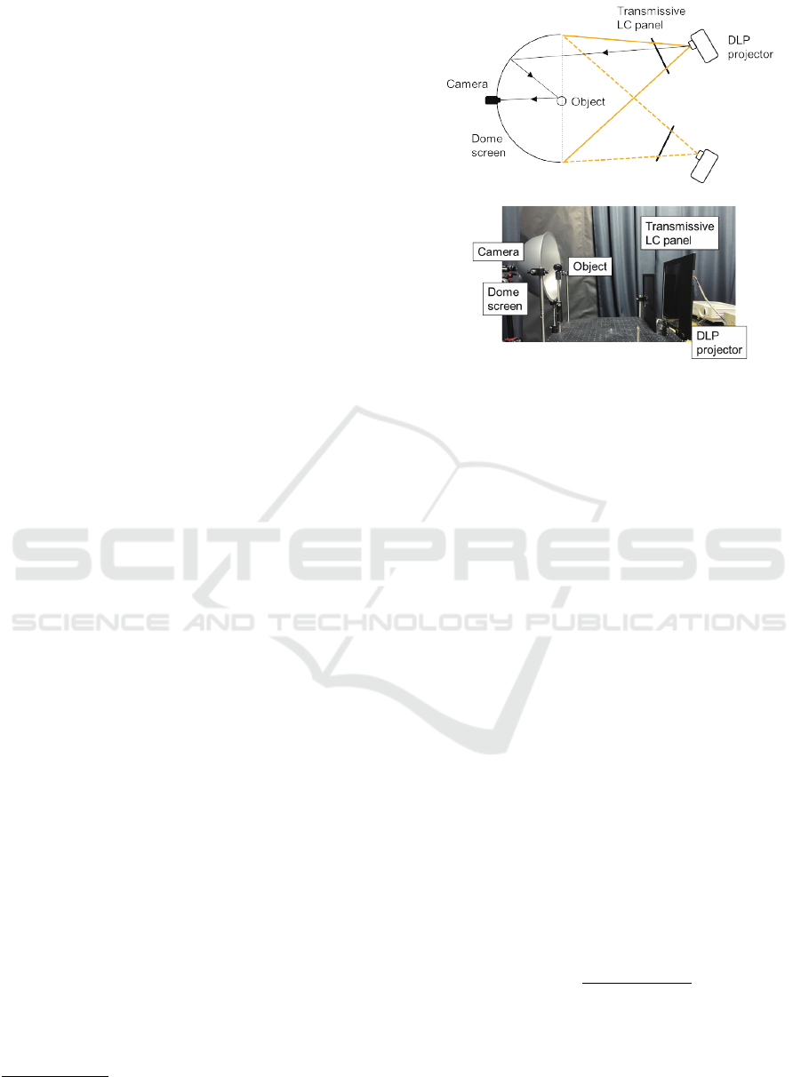
2.1 Lighting System
Figure 1 shows our setup using two pairs of a projec-
tor and a transmissive LC panel
1
, a dome screen, and
a color camera. First, the light ray emitted from the
projector passes through the transmissive LC panel.
Second, it is reflected on the dome screen and inci-
dent to a target object. Third, it is reflected on the sur-
face of the target object, and finally the reflected light
is observed by the camera. We assume that the dome
screen is distant from the target object, and denote the
direction of the incident light seen from the object by
(θ,φ). Here, θ and φ are the zenith and azimuth an-
gles of the global spherical coordinate system whose
pole is the camera direction.
The projector controls the per-pixel intensity of
the light ray. The front linear polarizer of the trans-
missive LC panel is removed, and then it controls
the per-pixel angle of linear polarization. In addition,
the polarization-preserving material is painted on the
dome screen. Thus, our lighting system enables us to
1
We explain the reason why the two pairs are required
in Section 3.2.
Figure 1: Our setup using two pairs of a projector and a
transmissive LC panel, a dome screen, and a color camera.
control the intensity L(θ,φ) and the angle of linear po-
larization ω(θ,φ) of the light ray coming from (θ, φ)
to the target object.
2.2 Manipulation
Let us consider a mirror surface that reflects the light
ray coming from the direction (θ, φ) to the camera.
Since the light ray is reflected to the direction of the
mirror reflection, the surface normal is represented as
(θ/2,φ) by using the spherical coordinate system. In
other words, the incident angle to the mirror surface
is θ/2. We denote θ/2 by θ
′
hereafter.
It is known that the specular reflectance is max-
imal/minimal when the polarization direction is per-
pendicular/parallel to the outgoing plane spanned by
the surface normal and the direction of the reflected
light, i.e. the s-polarized light/p-polarized light (Shur-
cliff, 1962; Wolff, 1990). Therefore, the intensity of
the reflected light I(θ,φ) illuminated by unpolarized
light is described by
I(θ, φ) = L(θ, φ)
¯
R(θ
′
). (1)
Here,
¯
R(θ
′
) is the average of the maximal reflectance
R
s
(θ
′
) and the minimal reflectance R
p
(θ
′
):
¯
R(θ
′
) =
R
s
(θ
′
) + R
p
(θ
′
)
2
. (2)
Our proposed method manipulates the gloss of
real object under omnidirectional lighting by control-
ling the intensity and the angle of linear polarization.
Specifically, we add the linear combination of spheri-
GRAPP 2025 - 20th International Conference on Computer Graphics Theory and Applications
430
cal harmonics to the intensity as
L
′
(θ,φ) = L(θ, φ) +
K
∑
k=0
k
∑
m=−k
a
km
Y
km
(θ,φ), (3)
where Y
km
(θ,φ) is the spherical harmonics of the k-
th degree and the m-th order and a
km
is its coefficient
of the linear combination. We denote the reflectance
depending on the angle of linear polarization ω(θ,φ)
by R(θ
′
,ω(θ,φ)).
Therefore, the intensity of the reflected light
I
′
(θ,φ) after manipulation is described by
I
′
(θ,φ) = L
′
(θ,φ)R(θ
′
,ω(θ,φ))
=
"
L(θ,φ) +
K
∑
k=0
k
∑
m=−k
a
km
Y
km
(θ,φ)
#
×R(θ
′
,ω(θ,φ)). (4)
Our proposed method controls the coefficients of the
linear combination a
km
(k = 1,2,3,...,K,|m| ≤ k) and
the angle of linear polarization ω(θ,φ) so that the
gloss, i.e. specular reflection components observed
on the target object is emphasized or suppressed as
expected.
2.3 Optimization
We denote the target ratio, i.e. the desired ratio of the
emphasized/suppressed intensity and the original in-
tensity of gloss (specular reflection components) by t.
Our proposed method controls the coefficients of the
linear combination a
km
and the angle of linear polar-
ization ω(θ,φ) so that
t ≃
I
′
(θ,φ)
I(θ, φ)
(5)
for all surface normals (θ
′
,φ) or equivalently for all
lighting directions (θ,φ).
In addition, our proposed method considers two
penalty terms. The first one termed F
1
is the penalty
on negative lighting intensities:
F
1
(θ,φ) = max(−L
′
(θ,φ),0). (6)
The second one termed F
2
is the penalty on the change
in diffuse reflection components:
F
2
=
K
∑
k=0
k
∑
m=−k
β
k
|a
k,m
|. (7)
Here, β
k
is the Fourier spectrum of the Lambertian
kernel; it represents the contribution of the Y
km
(θ,φ)
to the diffuse reflection components. It is known that
the first nine low-frequency terms, i.e. k = 0,1,2 ex-
plain the power of 99.2% of diffuse reflection compo-
nents (Ramamoorthi and Hanrahan, 2001a).
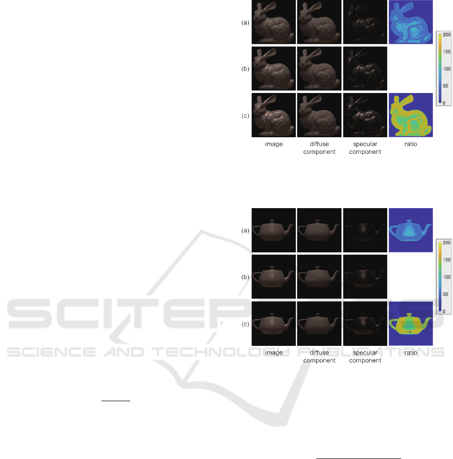
Figure 2: The results for the Stanford Bunny: (a) gloss
suppression (t = 0.5), (b) original, and (c) gloss emphasis
(t = 1.5) from top to bottom.
Figure 3: The results for the Utah Teapot: (a) gloss suppres-
sion (t = 0.5), (b) original, and (c) gloss emphasis (t = 1.5)
from top to bottom.
Thus, our proposed method results in the follow-
ing optimization:
min
a
a
a,ω
ω
ω
∑
θ,φ
L
′
(θ,φ)R(θ
′
,ω(θ,φ))
L(θ,φ)
¯
R(θ
′
)
−t
2
+λ
1
∑
θ,φ
F
1
(θ,φ) + λ
2
F
2
. (8)
Here, a
a
a = (a
00
,a
1−1
,a
10
,a
11
,···) and ω
ω
ω is the set
of the polarization angles for each lighting direction
(θ,φ). We denote the weights of the second and third
terms by λ
1
and λ
2
respectively. We solve the above
minimization via alternative optimization; we itera-
tively fix one of the a
a
a and ω
ω
ω and optimize the other.
Note that our proposed method is applicable to
rough surfaces although the above derivation assumes
the mirror surface. This is because we can assume
that rough surfaces consist of the micro-facets of mir-
rors with various surface normals, and the first term
Manipulating Gloss of Real Objects Under Omnidirectional Lighting
431
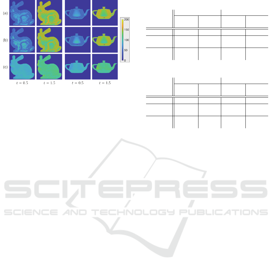
Figure 4: The ablation study for the Stanford Bunny (left)
and the Utah Teapot (right): (a) ours, (b) ours w/o high-
freq., and (c) ours w/o polarized from top to bottom.
in eq.(8) impose that the ratios for the all surface nor-
mals are close to the target ratio t.
3 EXPERIMENTS
3.1 Synthetic Images
First, we conducted the experiments using synthetic
images, for which the ground truth of diffuse and
specular reflection components are known, in order
to confirm the effectiveness of our proposed method
both qualitatively and quantitatively.
Setup:
We used the Stanford Bunny and the Utah Teapot
for the target objects and the Grace Cathedral from
the light probe image gallery (Debevec, 1998) for the
lighting environment. We used Mitsuba 3 for ren-
dering images. We solved the minimization prob-
lem of eq.(8) by using the trust region reflective al-
gorithm (Coleman and Li, 1996) (MATLAB function
of lsqnonlin). We set the weights in eq.(8) as λ
1
= 10
4
and λ
2
= 5 × 10
4
respectively.
Results:
Figure 2 shows the results for the Stanford Bunny: the
output images, the diffuse reflection components, the
specular reflection components, and the ratios (%) of
the suppressed/emphasized specular reflection com-
ponents and the original ones from left to right. Com-
paring (a) gloss suppression (t = 0.5), (b) original,
and (c) gloss emphasis (t = 1.5), we can qualitatively
see that our proposed method suppresses/emphasizes
specular reflection components as expected while it
preserves diffuse reflection components. We can also
see that the accuracy of gloss manipulation is rela-
tively low for points with surface normals toward the
camera direction. This is because the degree of lin-
Table 1: The quantitative evaluation for the Stanford Bunny.
t = 0.5 t = 1.5
Specular Diffuse Specular Diffuse
(ratio) (SSIM) (ratio) (SSIM)
Ours 58.89% 0.99997 140.97% 0.99998
Ours w/o 61.50% 1.00000 137.79% 1.00000
high-freq.
Ours w/o 91.73% 0.99991 108.61% 0.99991
polarized
Table 2: The quantitative evaluation for the Utah Teapot.
t = 0.5 t = 1.5
Specular Diffuse Specular Diffuse
(ratio) (SSIM) (ratio) (SSIM)
Ours 59.42% 1.00000 138.93% 1.00000
Ours w/o 61.49% 1.00000 136.49% 1.00000
high-freq.
Ours w/o 91.31% 0.99997 108.08% 0.99997
polarized
ear polarization is low for those points, and the effect
of polarized incident light is somewhat limited. We
can see that we obtain the similar results for the Utah
Teapot as shown in Figure 3.
Figure 4 (left) and Table 1 shows the qualitative
and quantitative evaluation of our proposed method
for the Stanford Bunny. We can see that our method
works well; the ratios of the suppressed/emphasized
specular reflection components and the original ones
are almost the same as the target values: t = 0.5 (50%)
and t = 1.5 (150%). We can see that our method
works better than the use of only one of the polar-
ized illumination (Ours w/o high-freq.) and high-
frequency illumination (Ours w/o polarized). We can
see that we obtain the similar results for the Utah
Teapot as shown in Figure 4 (right) and Table2.
3.2 Real Images
Second, we conducted the experiments using real im-
ages, for which the ground truth of diffuse and spec-
ular reflection components are unknown, in order to
confirm the effectiveness of our proposed method on
real images qualitatively.
Setup:
We used two pairs of a projector of MS524 from
BenQ and a transmissive LC panel, i.e. an LC panel
of JTP121LKNN from JNM Display without a front
polarization filter and a color camera of BFS-U3-
51S5PC-C from FLIR. We used two transmissive LC
panels because the range of the polarization angles of
each LC panel is at most 90
◦
as shown in Figure 5.
Then, we rotated one of the LC panel 90
◦
so that the
two LC panels covers the polarization angles from 0
◦
to 180
◦
.
GRAPP 2025 - 20th International Conference on Computer Graphics Theory and Applications
432
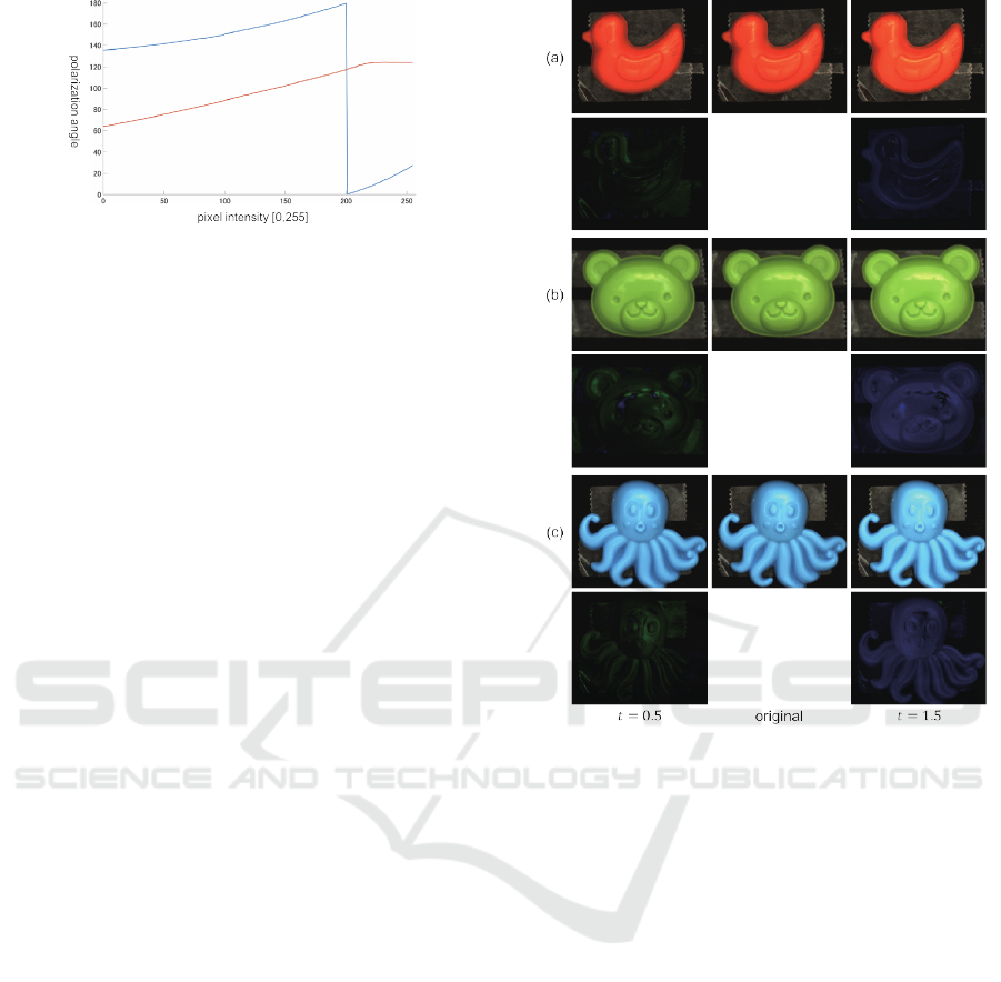
Figure 5: The polarization angles vs. the input pixel values
to the transmissive LC panels; the red and blue lines stand
for the polarization angle of the first and the second LC pan-
els. Note that the second LC panel is rotated 90
◦
.
We conducted the geometric calibration of our
setup by using a mirror sphere. Specifically, we
estimated the correspondence between the projector
pixel, the LC panel pixel, and (θ,φ) by using struc-
tured light patterns.
We conducted the photometric calibration of our
setup by using a reference object with known shape;
we used a smooth specular sphere without diffuse re-
flection components. Because the light rays incident
to an object surface from our lighting system is not
completely polarized but partially polarized, we made
the lookup table between the input pixel value to the
LC panel and R(θ
′
,ω(θ,φ)). Note that our proposed
method based on the above photometric calibration is
applicable to convex objects with the same refractive
index as the reference object.
In the same manner as the experiments using syn-
thetic images, we solved the minimization problem
of eq.(8) by using the trust region reflective algo-
rithm. We set the weights in eq.(8) as λ
1
= 10
4
and
λ
2
= 5 × 10
4
respectively.
Results:
Figure 6 shows the results for the plastics toys: (a)
bird, (b) bear, and (c) octopus under the illumination
environment of the Grace Cathedral. The green and
blue images under the suppressed and emphasized
images show the difference images from the original
ones; we represent the positive/negative pixel values
as B/G channels. We multiply the pixel values of the
difference images by 5 for display purpose.
We can qualitatively see that our proposed method
suppresses/emphasizes specular reflection compo-
nents as expected. Note that we achieve such gloss
manipulation without using the geometric and photo-
metric properties of the target objects. We can also
see that some artifacts are slightly visible due to cast
shadows caused at concave areas.
Figure 6: The results using real images of the plastics toys:
(a) bird, (b) bear, and (c) octopus.
4 CONCLUSION
We proposed a novel framework for manipulating the
gloss of real objects observed by our naked eyes un-
der omnidirectional lighting environments on the ba-
sis of the polarized and high-frequency illumination.
In order to control both the polarization angles and
high-frequency components of incident lighting en-
vironments, we built a novel lighting system by us-
ing a dome screen and two pairs of a projector and
a transmissive LC panel. We conducted a number of
experiments using both synthetic and real images, and
confirmed the effectiveness of our method.
One of the limitations of our proposed method is
the assumption of convex objects, i.e. no cast shad-
ows are observed on the objects’ surfaces. Another
limitation is the inter-reflection caused on the concave
screen. To cope with those limitations is the future
work of this study.
Manipulating Gloss of Real Objects Under Omnidirectional Lighting
433

ACKNOWLEDGEMENTS
This work was supported by JSPS KAKENHI Grant
Numbers JP20H00612 and JP22K17914.
REFERENCES
Coleman, T. F. and Li, Y. (1996). An interior trust region ap-
proach for nonlinear minimization subject to bounds.
SIAM Journal on Optimization, 6(2):418–445.
Debevec, P. (1998). Rendering synthetic objects into real
scenes: bridging traditional and image-based graph-
ics with global illumination and high dynamic range
photography. In Proceedings of the 25th Annual Con-
ference on Computer Graphics and Interactive Tech-
niques, pages 189–198.
Debevec, P. (2012). The Light Stages and Their Applica-
tions to Photoreal Digital Actors. In In Proc. SIG-
GRAPH Asia2012, Technical Briefs.
Debevec, P., Wenger, A., Tchou, C., Gardner, A., Waese,
J., and Hawkins, T. (2002). A lighting reproduc-
tion approach to live-action compositing. ACM Trans.
Graph., pages 547–556.
Ma, W.-C., Hawkins, T., Peers, P., Chabert, C.-F., Weiss,
M., and Debevec, P. (2007). Rapid acquisition of spec-
ular and diffuse normal maps from polarized spheri-
cal gradient illumination. In Proceedings of the 18th
Eurographics Conference on Rendering Techniques,
pages 183–194.
Ramamoorthi, R. and Hanrahan, P. (2001a). On the rela-
tionship between radiance and irradiance: determin-
ing the illumination from images of a convex lamber-
tian object. J. Opt. Soc. Am. A, 18(10):2448–2459.
Ramamoorthi, R. and Hanrahan, P. (2001b). A signal-
processing framework for inverse rendering. In Pro-
ceedings of the 28th Annual Conference on Computer
Graphics and Interactive Techniques, page 117–128.
Raskar, R., Welch, G., Low, K.-L., and Bandyopadhyay, D.
(2001). Shader lamps: Animating real objects with
image-based illumination. In In Proc. EGSR2001,
pages 89–102.
Shurcliff, W. (1962). Polarized Light: Production and Use.
Harvard University Press.
Siegl, C., Colaianni, M., Thies, L., Thies, J., Zollh
¨
ofer, M.,
Izadi, S., Stamminger, M., and Bauer, F. (2015). Real-
time pixel luminance optimization for dynamic multi-
projection mapping. ACM Trans. Graph., 34(6).
Wenger, A., Gardner, A., Tchou, C., Unger, J., Hawkins,
T., and Debevec, P. (2005). Performance relighting
and reflectance transformation with time-multiplexed
illumination. ACM Trans. Graph., 24(3):756–764.
Wolff, L. (1990). Polarization-based material classifica-
tion from specular reflection. IEEE Trans. PAMI,
12(11):1059–1071.
GRAPP 2025 - 20th International Conference on Computer Graphics Theory and Applications
434
